
SFP (Small Form-factor Pluggable) optical modules are compact, hot-pluggable transceivers that enable network equipment to connect seamlessly to fiber and copper links. These modules, including SFP, SFP+, and SFP28, are widely used in enterprise networks, data centers, and carrier-grade deployments to ensure high-speed, reliable connectivity.
This guide dives into the key SFP Optical Module Specifications that engineers, network architects, and procurement professionals rely on when evaluating optical transceivers. From electrical and optical parameters to environmental limits and diagnostic capabilities, we explain what each specification means in practice, how it affects real-world performance, and the critical considerations for deployment.
For those seeking a broader overview of optical transceivers and their applications, check out our [SFP Transceiver Guide], which provides a comprehensive reference for SFP, SFP+, and SFP28 modules.
Reading Value Promise: In just 10–15 minutes, this guide will equip you to interpret any SFP datasheet confidently. You’ll learn to extract essential details such as optical budget calculations, electrical compatibility, environmental tolerances, and DDM/DOM diagnostic data — enabling you to select, test, and deploy modules reliably in production networks.
➡️ What is an SFP Optical Module?
An SFP (Small Form-factor Pluggable) is a hot-pluggable, standardized transceiver module that converts electrical signals from a switch or router port into optical or copper signals for fiber or copper links. Modern SFP families include SFP (1–4 Gbps), SFP+ (up to 10 Gbps), and SFP28 (25 Gbps), providing scalable connectivity solutions for enterprise networks, data centers, and carrier deployments.
SFP Module Definition
SFP modules adhere to industry Multi-Source Agreements (MSA) that define mechanical dimensions, pinout configurations, and electrical interfaces. This standardization allows modules from different vendors to be physically interchangeable. However, electrical and optical compatibility must still be verified, including:
-
Supported line rates (e.g., 1G, 10G, 25G)
-
Connector type (LC, SC, or MPO)
-
Digital diagnostics monitoring (DDM/DOM) support
-
Host device compatibility (switches, routers, NICs)
Why this matters: Using modules that meet the mechanical MSA but are electrically or optically incompatible can result in link failures, high bit-error rates, or host port rejection. Engineers must check both the physical standard and the detailed datasheet specifications.
Practical Tips for Engineers
-
Always verify line rate compatibility with host switch or router.
-
Check connector type and ensure fiber match (OM3/OM4 MMF vs SMF).
-
Confirm DDM/DOM support for real-time monitoring of temperature, voltage, and Tx/Rx power.
-
Use vendor datasheets for electrical and optical parameter confirmation, not just MSA compliance.
-
Understand that physical interchangeability does not guarantee electrical interoperability — critical for high-speed links like 10G or 25G.
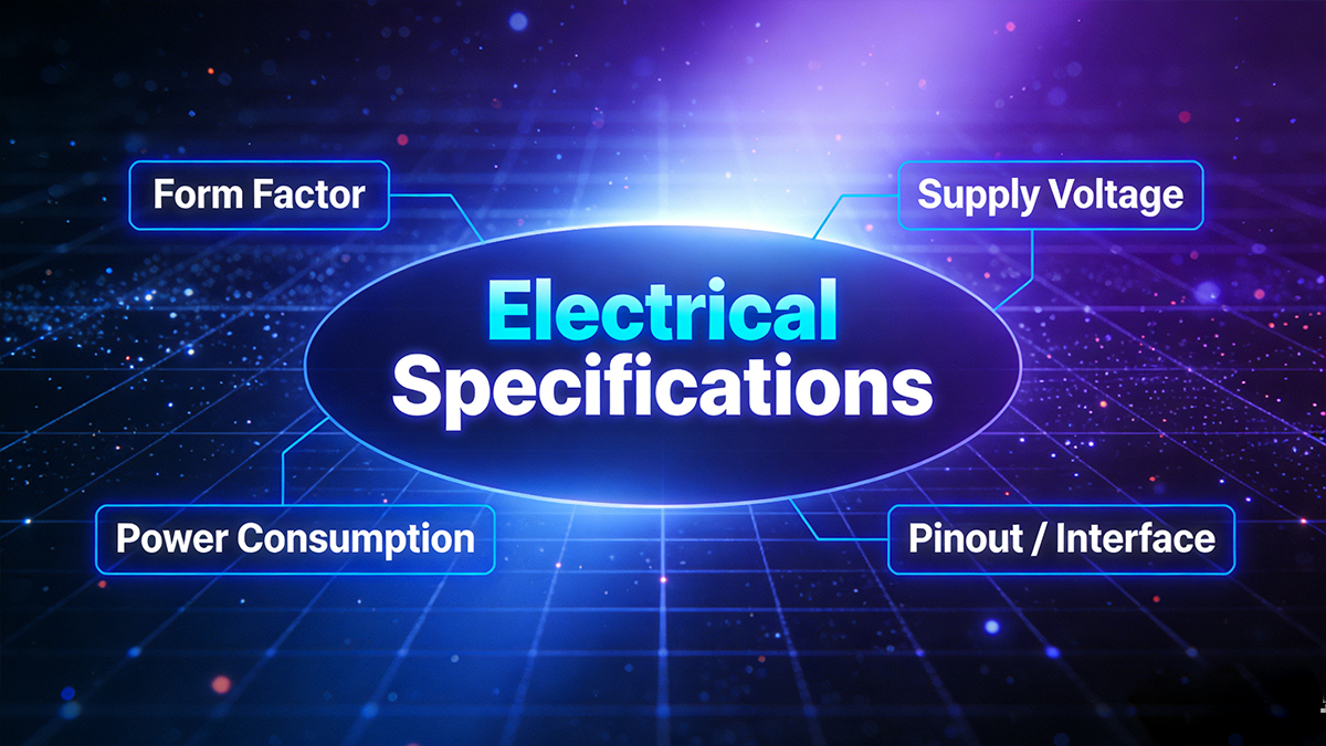
➡️ SFP Optical Module Electrical Specifications (Form-factor, Power, Pinout)
Electrical specifications define a module’s form-factor, pinout/interface, supply voltage, and power consumption, which are critical to ensure host board compatibility. These include the module type (SFP, SFP+, SFP28), differential TX/RX pairs, MOD-ABS, SCL/SDA for I²C, typical +3.3 V supply, and maximum power limits.
1. Form Factor
SFP modules conform to MSA-defined mechanical dimensions to guarantee proper fit in cages and LC connector sockets. Key families include:
-
SFP (Small Form-factor Pluggable): 1–4 Gbps, legacy Gigabit Ethernet
-
SFP+: up to 10 Gbps, commonly used in 10G Ethernet & data center links
-
SFP28: 25 Gbps, high-density 25G Ethernet applications
Engineer tip: Ensure the cage and connector on the host board match the intended module type; mechanical fit alone does not guarantee electrical compatibility.
2. Supply Voltage
-
Typical supply: +3.3 V ±5%
-
Some modules may specify tighter tolerances; always check the datasheet.
-
Critical for thermal and power budgeting in switches, routers, and servers.
Engineer tip: Use maximum power consumption values from the datasheet when designing airflow and thermal dissipation systems.
3. Power Consumption
Typical power ranges by module type:
| Module Type |
Typical Power (W) |
Notes |
| SFP Module |
0.5 – 1.0 |
Lower speed, short-reach links |
| SFP+ Module |
1.0 – 2.0 |
Depends on optical output power and line rate |
| SFP28 Module |
1.0 – 2.0 |
Similar to SFP+, may vary with vendor |
Engineer tip: Always consider max-rated power for thermal design, not just typical values.
4. Pinout / Module Interface
SFP modules follow standard MSA pinouts for electrical and control signals:
-
TX+/TX- and RX+/RX-: Differential pairs for data
-
MOD-ABS: Module presence detection
-
LOS (Loss of Signal): TTL logic output indicating link status
-
SCL/SDA: I²C interface for Digital Diagnostics Monitoring (DDM/DOM) per SFF-8472
Engineer tip: Verify host board mapping; some switches/routers may reject non-certified vendors unless “unlocked.”
5. Link Partner & Host Compatibility
-
Some host devices limit which vendor modules can be used.
-
Always consult vendor compatibility lists or support documentation.
-
Using an unsupported module may result in port errors, LOS issues, or non-recognition.
6. Typical Electrical Values
| Parameter |
Typical / Range |
Notes |
| Supply voltage |
3.3 V ±5% |
Check SFP datasheet for exact tolerance |
| Power consumption (SFP) |
0.5 – 1.0 W |
Typical operating range |
| Power consumption (SFP+) |
1.0 – 2.0 W |
Depends on optical output |
| I²C interface |
100 kHz / 400 kHz |
SFF-8472 compatible |
| LOS (Loss of Signal) |
TTL logic |
Active-high or low per datasheet |
Table note: These are typical ranges; always validate against the vendor datasheet before deployment.
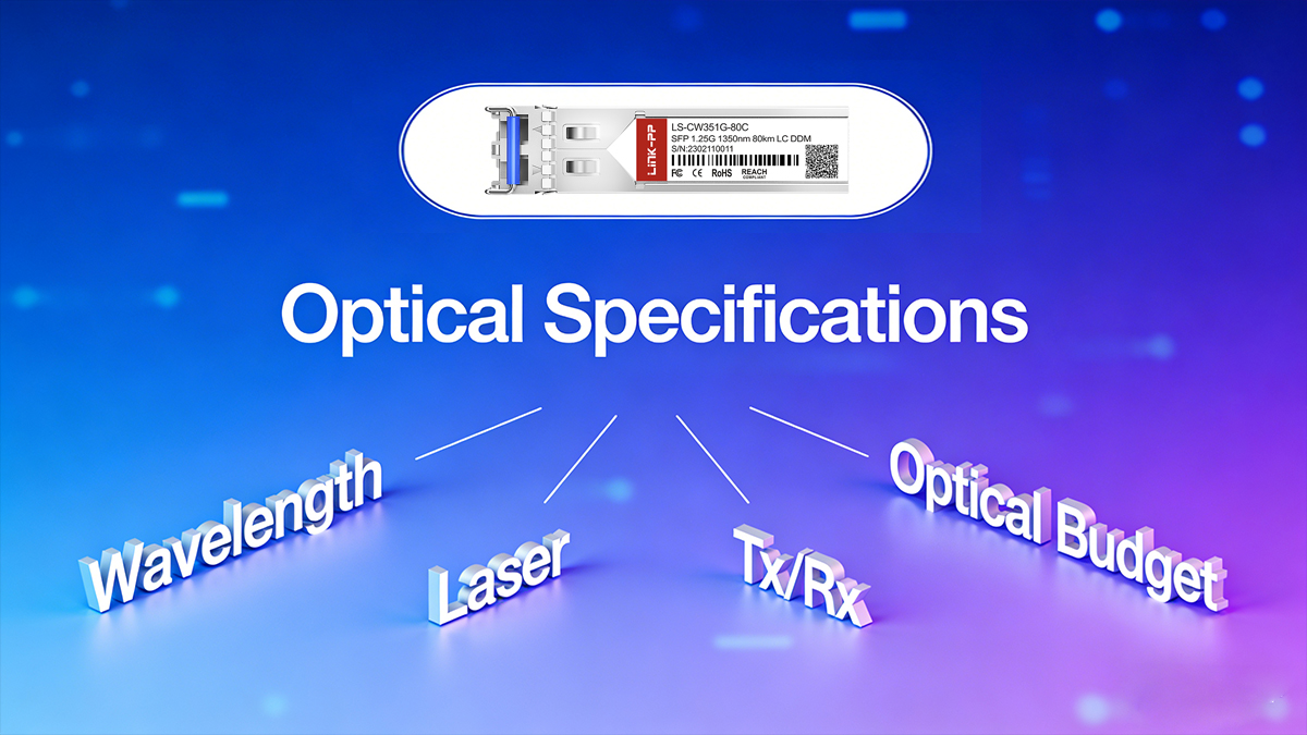
➡️ Optical Specifications Explained (Wavelength, Tx/Rx, Optical Budget)
Optical specifications determine the fiber type and maximum distance a module can support. Key parameters include center wavelength, transmitter output power (Tx), receiver sensitivity (Rx), and the optical budget (Tx–Rx margin). The optical budget must exceed total link loss plus a safety margin to ensure reliable performance.
● Wavelength / Laser Type
SFP Optical modules use different laser types depending on fiber type and reach:
| Wavelength |
Laser Type |
Fiber Type |
Typical Reach |
Notes |
| 850nm |
VCSEL |
MMF |
Up to 300 m (OM3/OM4) |
Short-reach, high-density data centers |
| 1310nm |
FP / DFB |
SMF |
Up to 10 km |
Medium reach, enterprise links |
| 1550nm |
DFB / CWDM / DWDM |
SMF |
40–80 km+ |
Long-reach, amplified or metro links |
Engineer tip: Choose wavelength according to fiber type, link distance, and dispersion budget. Multimode fiber is common for short-reach connections; single-mode for longer distances.
● Transmitter (Tx) and Receiver (Rx) Specifications
-
Tx Optical Power (dBm): Power emitted by the transmitter. Datasheets list min/typical/max values.
-
Rx Sensitivity (dBm): Minimum received power to meet Bit Error Rate (BER) requirements, often BER = 10⁻¹².
-
Connector Type: LC duplex connectors are most common for SFP modules; SC connectors are rare in modern designs.
-
Laser Safety Class: Typically Class 1 — safe for normal operation.
-
Extinction Ratio / Rise-Fall Times: Important for high-speed modules (SFP+, SFP28) to maintain signal integrity.
Example ranges (illustrative):
| Parameter |
Typical Range |
Notes |
| Tx Power |
-9 dBm to +3 dBm |
Short-reach modules emit lower power; long-reach higher |
| Rx Sensitivity |
-20 dBm to -3 dBm |
Depends on module speed and FEC |
| Optical Budget |
10–16 dB |
For 10 km SMF links, depending on module class |
● Optical Budget Calculation
Definition: Optical budget = Tx (min or typical) − Rx (min). Use worst-case values: Tx min − Rx max or follow vendor guidance.
Recommended practice:
Required optical budget = Passive losses (fiber + connectors + splices) + Safety margin (2–3 dB) + Aging margin Ensure module optical budget ≥ required optical budget
Engineer tip: Always perform a link budget calculation before deployment. Ignoring optical budget can result in link errors, intermittent connectivity, or high BER.
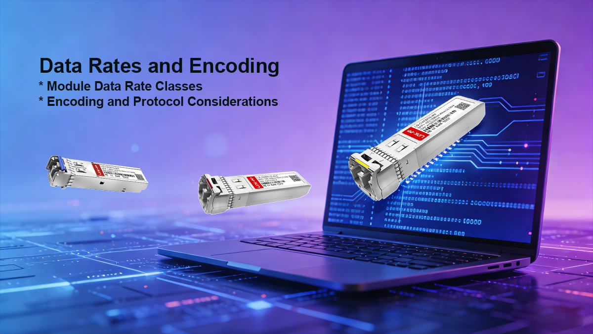
➡️ SFP Optical Module Data Rates and Encoding (SFP, SFP+, SFP28)
The data rate class defines which modules are suitable for a given network: legacy SFP modules support 1 Gbps/2.5 Gbps, SFP+ supports 10 Gbps, and SFP28 supports 25 Gbps single-lane links. However, PHY encoding, lane count, and host MAC/PHY compatibility determine actual interoperability beyond the nominal rates.
Module Data Rate Classes
| Module Type |
Typical Data Rate |
Common Standards |
Notes |
| SFP |
1–4 Gbps |
1GBASE-SX/LX, 2.5G Ethernet, Fibre Channel |
Legacy Ethernet & storage applications |
| SFP+ |
10 Gbps |
10GBASE-SR/LR, 10G Fibre Channel |
Requires tighter signal integrity; may have higher power consumption |
| SFP28 |
25 Gbps |
25GBASE-SR/ER, IEEE 802.3by |
Single-lane high-speed Ethernet; increasingly used in data centers |
Engineer tip: Check host device compatibility; some switches and NICs may limit which module types or vendors can be used.
Encoding and Protocol Considerations
-
SFP / SFP+:
-
10G modules use 10GBASE-R with 64b/66b encoding for Ethernet.
-
Fibre Channel, SONET/SDH modules have different PCS encoding schemes; ensure protocol alignment.
-
SFP28:
-
Compliant with IEEE 802.3by, single-lane 25G Ethernet encoding.
-
Backward-compatible at 10G with proper PHY support, depending on host.
Engineer tip: Even if physical and nominal rates match, mismatched encoding or lane configuration can prevent link negotiation or cause errors. Always consult the host MAC/PHY datasheet.
Practical Deployment Tips
-
Verify module speed matches the host port capability.
-
Confirm encoding standard if using Fibre Channel, SONET/SDH, or multi-rate Ethernet.
-
Check for lane count compatibility (SFP/SFP+ are single-lane; some high-speed QSFP modules use 4 lanes).
-
Review vendor compatibility matrices for your switch/router.
➡️ Diagnostics & Management (DDM/DOM, I²C, SFF-8472)
Modern SFP Optical Modules implement Digital Diagnostics Monitoring (DDM) or Digital Optical Monitoring (DOM) over I²C (per SFF-8472) to report real-time parameters such as Tx/Rx optical power, module temperature, supply voltage, and laser bias current. These diagnostics are critical for remote monitoring, fault detection, and proactive maintenance in enterprise and data center networks.

Common DDM/DOM Fields
| Parameter |
Units |
Purpose / Notes |
| Transceiver temperature |
°C |
Detect overheating or abnormal thermal conditions |
| Supply voltage |
V |
Ensures proper electrical operation and avoids undervoltage/overvoltage faults |
| Laser bias current |
mA |
Monitors laser health and degradation over time |
| Transmit optical power (Tx) |
dBm |
Confirms output power is within specification |
| Receive optical power (Rx) |
dBm |
Confirms received signal is adequate |
| Alarm / warning thresholds |
Programmable |
Some modules allow host-side threshold configuration for alerts |
Engineer tip: Use host monitoring software to detect gradual degradation, such as decreasing Rx power or increasing laser bias current, to schedule fiber or module maintenance before link failure occurs.
I²C Interface and SFF-8472 Standard
-
DDM/DOM communicates over I²C interface, typically at 100 kHz or 400 kHz.
-
Standardized by SFF-8472, specifying memory addresses, registers, and conversion formulas for diagnostics.
-
Ensures interoperability between different vendors’ modules and host devices.
Engineer note: Most network switches and optical monitoring software can poll these registers periodically to provide alerts, trend analysis, and predictive maintenance reports.
➡️ Environmental & Mechanical Specs (Temp, MTBF, Connectors)
Environmental and mechanical specifications determine whether an SFP Optical Module is suitable for commercial, industrial, or extended-temperature deployments. Key parameters include operating and storage temperature ranges, humidity tolerance, shock and vibration resistance, MTBF, and mechanical form-factor (locking mechanism, latch type, and dimensions). Connector type and fiber compatibility are also critical for reliable network deployment.
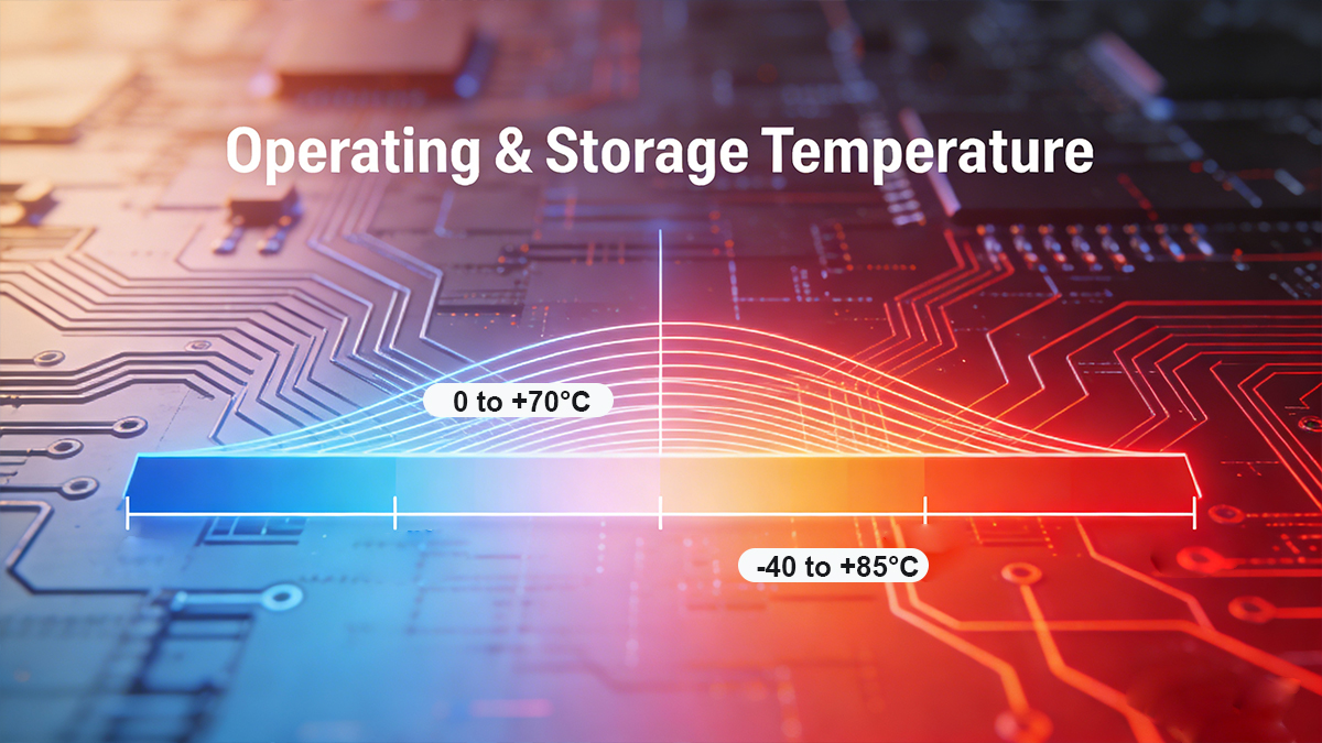
1. Operating & Storage Temperature
| Category |
Temperature Range |
Typical Use Case |
| Commercial |
0 °C to +70 °C |
Standard office / data center deployments |
| Industrial / Extended Temp |
−40 °C to +85 °C |
Harsh environments, telecom shelters, industrial sites |
| Storage |
−40 °C to +85 °C |
Module shipping and storage conditions |
Engineer tip: Ensure modules meet your deployment environment requirements; extended-temperature SFPs are essential for outdoor cabinets or industrial switches.
2. Humidity, Shock, Vibration & MTBF
| Parameter |
Typical Range / Rating |
Notes |
| Humidity |
5–95% RH non-condensing |
Standard datasheet value for safe operation |
| Shock / Vibration |
Per MSA test conditions |
Ensures module reliability under transport and installation stress |
| MTBF |
>500,000 hours |
Useful for network reliability planning and lifecycle estimation |
Engineer tip: MTBF is a statistical measure — higher MTBF indicates longer expected operational life but does not guarantee failure-free operation. Combine with environmental compliance for accurate reliability assessment.
3. Mechanical Form Factor & Connector Type
-
Form Factor / Locking Mechanism: MSA-compliant dimensions ensure modules fit standard cages and LC duplex ports; latch types prevent accidental disconnection.
-
Keying: Physical keying prevents incorrect module insertion.
-
Connectors:
-
Fiber Types:
-
MMF: OM1, OM2, OM3, OM4, OM5 for short-reach links
-
SMF: ITU-T G.652 / G.657 for long-reach fiber connections
Engineer tip: Always match the SFP module connector and fiber type to the host port and cabling infrastructure.
Deployment Notes:
-
Verify operating temperature matches your environment (commercial vs industrial).
-
Check MTBF to plan for module lifecycle and maintenance scheduling.
-
Ensure mechanical compliance with cages, latches, and keying for safe installation.
-
Match connector type and fiber standard for proper optical link performance.
-
Confirm shock, vibration, and humidity ratings for outdoor or harsh environments.
➡️ SFP Optical Module Standards and MSA Compliance
SFP optical modules must conform to industry standards and regulatory requirements to ensure safe, reliable operation and interoperability. Key compliance areas include MSAs, IEEE 802.3 Ethernet standards, RoHS, EMC, and fiber-specific optical standards. Successful interoperability relies on matching standards and verifying vendor compatibility lists.
Key Standards to Check
| Category |
Standard |
Purpose / Notes |
| MSA (Multi-Source Agreement) |
SFF-8472 |
Defines DDM/DOM monitoring registers and I²C interface |
| |
SFF-8431 |
10G electrical interface standard for SFP+ modules |
| |
SFF-8432 |
Mechanical and electrical SFP MSA (form-factor, pinout) |
| Ethernet |
IEEE 802.3 |
1G/10G/25G standards for data rate, PCS, encoding |
| Safety / EMC |
RoHS |
Restriction of hazardous substances |
| |
CE / FCC |
Electrical safety and electromagnetic compatibility |
| Optical / Fiber |
ITU-T G.652 / G.657, TIA/EIA |
Defines single-mode and multimode fiber characteristics, wavelength standards |
Interoperability Considerations
-
Some switch vendors enforce “vendor whitelists”; using non-certified modules may cause port rejection or link errors.
-
Always check supported optics lists or request vendor certification when deploying third-party SFP.
-
Matching data rate, line encoding, lane configuration, and host PHY is as important as physical and electrical compliance.
Practical tip: Even if a SFP Optical Module is MSA-compliant, electrical, optical, and host compatibility must be verified to ensure full interoperability in production networks.
➡️ How to Read an SFP Datasheet — Step-by-Step Checklist
To evaluate any SFP optical module, scan the SFP Module Datasheet systematically for supported PHY/line rates, optical parameters (Tx/Rx min/typ/max), optical budget & reach, electrical/power specs, environmental/mechanical ratings, and diagnostic capabilities (DDM/DOM). This ensures accurate module selection, deployment, and interoperability verification.
Step-by-step
-
Header: confirm module family (SFP/SFP+/SFP28) and part number.
-
Applications: see supported standards (e.g., 10GBASE-SR, 1GBASE-LX).
-
Absolute maximum ratings: note extremes not to be exceeded.
-
Electrical characteristics: voltage, power consumption (max).
-
Optical characteristics: Tx/Rx min/typ/max, wavelength, receiver overload.
-
Optical budget & reach: check typical reach and any FEC assumptions.
-
Timing & jitter: if relevant for high-speed links.
-
Mechanical drawings: for PCB/cage fit and LC clearance.
-
Regulatory & environmental: temperature, MTBF, certifications.
-
EEPROM map / I²C memory map: for inventory and DDM fields.
Red flags: missing Rx sensitivity numbers, unspecified optical budget, or absent DDM support.
Testing & Validation Checklist Before SFP Optical Module Deployment
Before deploying SFP optical transceivers, validate them with loopback tests, live link testing at target data rates, DDM/DOM monitoring, BER testing, and environmental stress tests. This ensures modules operate reliably under production conditions and meet performance and interoperability expectations.
Minimum validation steps
-
Verify host acceptance: module recognized; correct rate negotiated.
-
Link tests: establish link at target speed; verify throughput.
-
BER test: target BER (e.g., 10⁻¹²) or vendor-specified threshold.
-
DDM sanity checks: read Tx/Rx power and temperature.
-
Optical power test: measure actual Tx power & Rx power on both ends.
-
Environmental test: sample units in temperature chamber if deployed in extremes.
-
Firmware / compatibility test: ensure host firmware does not block third-party optics.
➡️ FAQ for SFP Optical Module Specifications
Q1: Can I mix SFP and SFP+ modules on the same switch?
A: Only if the host port supports rate negotiation and the module is within the supported PHY range. SFP+ ports often accept SFP modules at lower speeds, but check vendor documentation.
Q2: How do I compute optical budget?
A: Optical budget = Tx power (dBm) − Rx sensitivity (dBm). Subtract cable/connectors loss and add a margin (2–3 dB) for safety.
Q3: What is DDM/DOM and why is it important?
A: Digital Diagnostics Monitoring (DOM) exposes real-time Tx/Rx power, temperature, and voltage over I²C, helping remote troubleshooting and predictive maintenance.
Q4: How do I choose the right SFP module for my network?
A: Consider data rate, fiber type (MMF or SMF), wavelength, reach, host compatibility, and environmental ratings. Check the module’s datasheet for Tx/Rx power, optical budget, temperature range, and DDM/DOM support.
Q5: Can I mix LINK-PP and Cisco SFP modules?
A: Yes, if the modules comply with MSA standards and the host switch supports third-party optics. Always verify vendor compatibility lists and test modules for link stability.
Q6: What environmental specs should I check?
A: Check operating/storage temperature, humidity, shock/vibration, and MTBF. Industrial or outdoor deployments require extended temperature modules (−40 °C to +85 °C).
Q7: How do I read an SFP datasheet effectively?
A: Follow a step-by-step checklist: verify module family, supported standards, electrical/optical parameters, optical budget, mechanical/environmental specs, and DDM/DOM capabilities.
Q8: What testing is recommended before deploying SFP modules?
A: Perform host acceptance, live link tests, BER verification, DDM checks, optical power measurement, environmental stress tests, and firmware/compatibility validation.
➡️ Conclusion
Understanding SFP Optical Module Specifications goes far beyond checking nominal data rates or transmission distance. Reading SFP datasheets effectively means focusing on optical budget, electrical compatibility, diagnostic capabilities (DDM/DOM), and environmental ratings — these are the parameters that ultimately determine real-world interoperability, long-term reliability, and deployment success.
By systematically evaluating Tx/Rx margins, host interface requirements, monitoring features, and operating conditions, engineers and network operators can avoid common compatibility issues, reduce unexpected downtime, and deploy optical links with confidence across enterprise, data center, and industrial environments.
| Parameter |
SFP (1G) typical |
SFP+ (10G) typical |
SFP28 (25G) typical |
| Supported data rates |
1.25 Gbps, 1G |
10.3125 Gbps |
25.78 Gbps |
| Wavelength (example) |
850 nm (MMF) / 1310 nm (SMF) |
850 / 1310 / 1550 nm |
1310 / 1550 nm |
| Tx power (typ) |
-9 to -3 dBm |
-7 to 0 dBm |
-6 to +1 dBm |
| Rx sensitivity (typ) |
-20 dBm |
-14 dBm |
-12 dBm |
| Reach (typ) |
300 m (OM3) / 10 km (SMF) |
300 m to 10 km |
10 km+ (SMF) |
| Power consumption |
0.5–1.0 W |
1.0–2.0 W |
1.0–2.5 W |
| DDM/DOM |
Optional/standard |
Common |
Common |
| Temp range |
0–70 °C / -40–85 °C avail. |
0–70 °C / -40–85 °C avail. |
0–70 °C / -40–85 °C avail. |
Looking to source reliable, standards-compliant SFP Optical Modules for your network deployment?
? To explore high-quality SFP optical modules and get technical support for your design or purchase, check out the LINK-PP Official Store — your source for standards-compliant optics.
Author Information
-
Author: Technical Content Lead, Optical Modules — 10+ years in telecom optics, datasheet author.
-
Company: LINK-PP (manufacturer & supplier of transceivers and optical modules).
-
Contact: [LINK-PP Official Store] | Support: [email protected]
-
Copyright: © LINK-PP. Last updated: Jan 16, 2026.


