As modern Ethernet, data center, and fiber-optic networks continue to scale, network connectivity has increasingly shifted from fixed interfaces to modular, hot-pluggable transceiver designs. This architectural approach allows network operators to adapt link speed, transmission distance, and media type without replacing core networking equipment. Within this ecosystem, the SFP (Small Form-Factor Pluggable) transceiver has become one of the most widely adopted interface standards across switches, routers, firewalls, and telecom platforms.
An SFP transceiver integrates both transmitting and receiving functions into a compact, standardized module, enabling seamless conversion between electrical and optical signals. Its flexibility supports a broad range of applications—from short-reach enterprise connections to long-haul single-mode fiber links—while maintaining interoperability across multi-vendor environments. Understanding how SFP transceivers work, the differences between available types, and the key considerations when selecting the right module is essential for building reliable, scalable network infrastructures.
What You Will Learn from This Guide
This guide is designed to provide a clear and practical understanding of SFP transceivers, from fundamental concepts to real-world selection considerations. By the end of this article, you will be able to:
-
Understand what an SFP transceiver is and how it functions within Ethernet and fiber-optic networks
-
Learn how SFP transceivers work, including signal conversion, hot-pluggable design, and monitoring capabilities
-
Differentiate between major SFP types, such as SFP, SFP+, and SFP28, and understand where each is best applied
-
Identify key technical specifications—including data rate, wavelength, transmission distance, and fiber type
-
Select the right SFP transceiver based on network equipment compatibility, deployment scenarios, and long-term scalability
-
Avoid common compatibility and deployment issues encountered in multi-vendor network environments
Whether you are a network engineer, system integrator, or procurement professional, this guide will help you make informed decisions when evaluating and deploying SFP transceivers in enterprise, data center, or telecom networks.
✅ What Is an SFP Transceiver?
An SFP transceiver is a compact, hot-pluggable network module that enables network devices to transmit and receive data over fiber-optic or copper cabling. The term SFP stands for Small Form-Factor Pluggable, referring to its standardized size and interface, which allow the module to be easily inserted into or removed from compatible network equipment without powering down the system.
In practical terms, an SFP transceiver serves as the physical interface between a network device and the transmission medium, converting electrical signals generated by switches or routers into optical signals for fiber links—or vice versa on the receiving end.
Key Characteristics of an SFP Transceiver
-
Hot-pluggable design
SFP transceivers can be installed or replaced while the network device is operating, minimizing downtime during maintenance or upgrades.
-
Standardized form factor
Defined by industry Multi-Source Agreement (MSA) standards, SFP modules are designed to be interoperable across a wide range of vendors and platforms.
-
Integrated transmitter and receiver
Each SFP module combines optical (or electrical) transmission and reception functions in a single, compact unit.
-
Support for multiple media types
SFP transceivers are available for single-mode fiber, multi-mode fiber, and copper Ethernet connections, enabling flexible network design.
Because of these characteristics, SFP transceivers are widely used in enterprise networks, data centers, and telecom infrastructures, where scalability, compatibility, and ease of deployment are critical requirements.
SFP Transceiver vs. SFP Module: Is There a Difference?
In most networking contexts, the terms “SFP transceiver” and “SFP module” are used interchangeably. Both refer to the same pluggable device that performs signal transmission and reception. The term transceiver emphasizes the functional role (transmit + receive), while module highlights its physical, replaceable form factor.
✅ How Does an SFP Transceiver Work?
An SFP transceiver works by converting electrical signals generated by network equipment into optical or electrical signals suitable for transmission, and then converting incoming signals back into electrical form at the receiving end. This bidirectional process allows switches, routers, and other network devices to communicate over fiber-optic or copper links using a standardized, pluggable interface.
At a high level, an SFP transceiver operates through a transmit path and a receive path, both integrated within a single compact module.
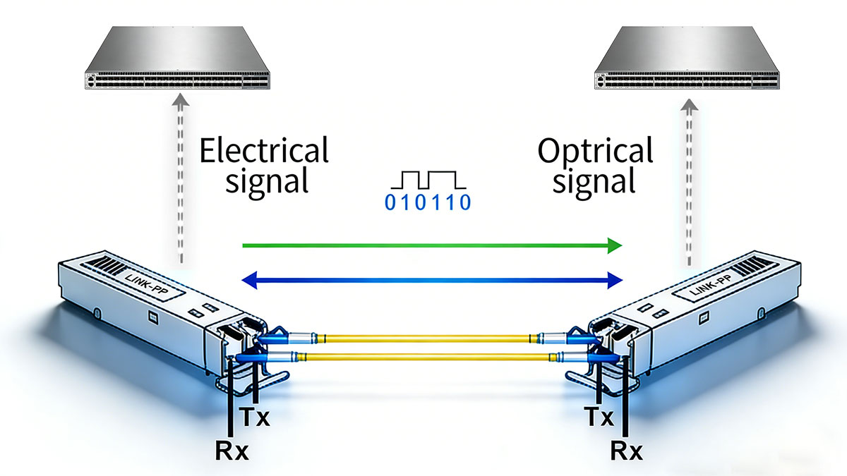
Electrical-to-Optical Signal Conversion
When data is sent from a network device, the electrical signal enters the SFP transceiver through the host interface.
Transmitter Function
Inside the SFP module, the transmitter section performs the following steps:
-
Electrical signal conditioning
The incoming electrical data stream is processed to ensure signal integrity and timing accuracy.
-
Optical signal generation
The conditioned signal drives a light source—typically a laser diode or LED, depending on the module type—converting the electrical data into modulated optical pulses.
-
Optical coupling into the fiber
The generated light is precisely aligned and coupled into the connected fiber-optic cable through the module’s optical connector.
This conversion enables high-speed data transmission over long distances with low signal loss, especially in single-mode fiber applications.
Optical-to-Electrical Signal Conversion
At the receiving end of the link, the process is reversed.
Receiver Function
The receiver section of the SFP transceiver carries out the following operations:
-
Optical signal detection
Incoming light signals are captured by a photodiode (such as a PIN or APD detector).
-
Signal amplification and recovery
The weak electrical signal produced by the photodiode is amplified and reshaped to restore the original data pattern.
-
Electrical output to the host device
The recovered electrical signal is delivered back to the switch or router for further processing.
This bidirectional transmission allows a single SFP transceiver to maintain continuous, full-duplex communication over the network link.
Hot-Pluggable Operation and Module Detection
One of the defining characteristics of SFP transceivers is their hot-pluggable design.
What Hot-Pluggable Means
-
SFP modules can be inserted or removed without powering down the host device
-
The host system automatically detects the presence of the module
-
Link parameters are negotiated once the module is installed
This capability significantly reduces maintenance windows and supports flexible network expansion.
Digital Diagnostic Monitoring (DDM)
Many modern SFP transceivers support Digital Diagnostic Monitoring (DDM), which provides real-time visibility into module operating conditions.
Typical DDM Parameters
-
Module temperature
-
Supply voltage
-
Transmit optical power
-
Receive optical power
By monitoring these parameters, network operators can proactively identify performance degradation, fiber issues, or environmental problems before they result in link failures.
Summary of the SFP Transceiver Working Principle
In summary, an SFP transceiver works by:
-
Receiving electrical data from a network device
-
Converting the data into optical or electrical transmission signals
-
Transmitting the signal over fiber or copper media
-
Receiving the incoming signal from the remote end
-
Converting it back into electrical form for the host system
This standardized operating model is what makes SFP transceivers a foundational building block for scalable and interoperable network architectures.
✅ Types of SFP Transceivers Explained
SFP transceivers are available in multiple variants to support different data rates, transmission media, and network applications. Understanding these classifications is essential for selecting the correct module and ensuring compatibility with network equipment. The most common ways to categorize SFP transceivers are by data rate, fiber type, and transmission medium.
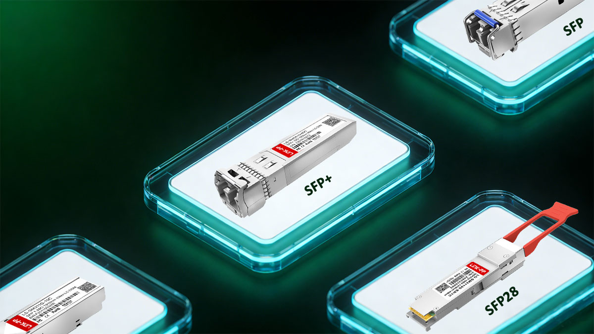
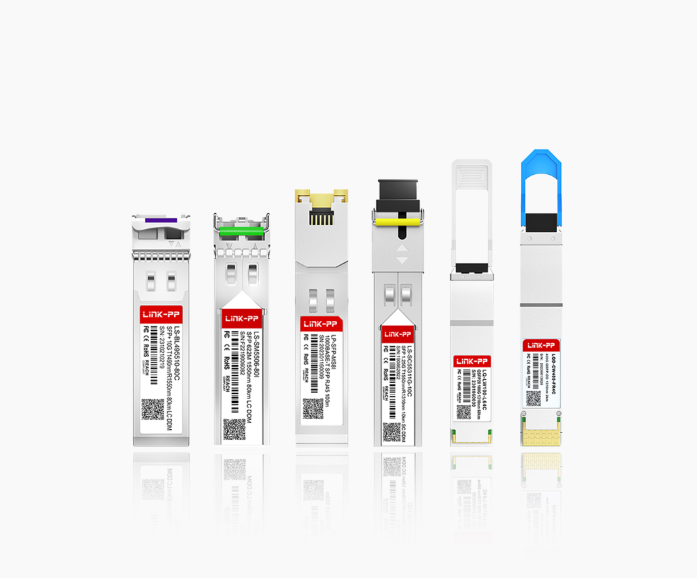
SFP vs. SFP+ vs. SFP28
One of the most frequently searched topics related to SFP transceivers is the difference between SFP, SFP+, and SFP28. While these modules share a similar physical form factor, they are designed for different performance levels.
Standard SFP transceivers are typically used for 1 Gigabit Ethernet (1000BASE-X) applications.
-
Common speeds: 1 Gbps
-
Typical use cases: Enterprise access networks, campus networks
-
Common standards: 1000BASE-SX, 1000BASE-LX, 1000BASE-T
SFP+ transceivers support 10 Gigabit Ethernet and are widely deployed in data centers and high-performance enterprise networks.
-
Common speeds: 10 Gbps
-
Typical use cases: Data center aggregation, server interconnects
-
Common standards: 10GBASE-SR, 10GBASE-LR, 10GBASE-T
SFP28 transceivers are designed for 25 Gigabit Ethernet, offering higher bandwidth while maintaining the same compact form factor.
-
Common speeds: 25 Gbps
-
Typical use cases: Modern data centers, 5G fronthaul and backhaul
-
Common standards: 25GBASE-SR, 25GBASE-LR
Although SFP, SFP+, and SFP28 modules are physically similar, they are not universally interchangeable. Port capability and switch platform support must be verified before deployment.
Single-Mode vs. Multi-Mode SFP Transceivers
Another important classification of SFP transceivers is based on the type of optical fiber they are designed to work with.
Single-mode SFP modules are optimized for long-distance transmission using single-mode fiber (SMF).
-
Typical wavelengths: 1310 nm, 1550 nm
-
Transmission distance: Up to tens of kilometers
-
Common applications: Telecom networks, FTTx, long-haul enterprise links
Multi-mode SFP modules are intended for short-reach connections using multi-mode fiber (MMF).
-
Typical wavelength: 850 nm
-
Transmission distance: Typically up to a few hundred meters
-
Common applications: Data centers, intra-building links
Choosing the correct fiber type is critical, as single-mode and multi-mode SFP transceivers are not cross-compatible.
Fiber SFP vs. Copper RJ45 SFP
SFP transceivers can also be categorized by the transmission medium they support.
Fiber-Optic SFP Transceivers
Fiber SFP modules use optical fiber as the transmission medium and are preferred for:
-
High-speed data transmission
-
Long-distance connectivity
-
Electromagnetic interference resistance
These modules are commonly deployed in data centers and backbone networks.
Copper RJ45 SFP Transceivers
Copper SFP transceivers support Ethernet over twisted-pair copper cabling.
Copper SFP modules provide flexibility in mixed-media environments but typically consume more power and have shorter reach compared to fiber SFPs.
Special-Purpose and Extended SFP Types
Beyond standard Ethernet applications, SFP transceivers are also available for specialized use cases.
Industrial and Extended-Temperature SFPs
-
Designed for harsh environments
-
Support extended operating temperature ranges
-
Used in industrial automation and outdoor deployments
CWDM and DWDM SFP Transceivers
-
Support wavelength-division multiplexing
-
Enable multiple optical signals over a single fiber
-
Common in metro and telecom networks
Summary of SFP Transceiver Types
| Classification Dimension |
SFP Transceiver Categories |
Description |
| Data Rate |
SFP, SFP+, SFP28 |
Defines supported speed: 1G, 10G, and 25G respectively |
| Fiber Type |
Single-mode (SMF), Multi-mode (MMF) |
Determines reach, wavelength, and deployment environment |
| Transmission Medium |
Fiber optic, Copper (RJ45) |
Optical fiber for long distance, copper for short-range Ethernet |
| Application Scenario |
Enterprise, Data Center, Telecom, Industrial |
Different use cases require specific performance, reach, and temperature ratings |
Classifying SFP transceivers across these dimensions helps engineers select the correct module, avoid compatibility issues, and design networks that scale reliably over time.
✅ SFP Transceiver Specifications You Should Know
When selecting an SFP transceiver, understanding its technical specifications is critical to ensuring network compatibility, performance stability, and link reliability. Network engineers often search for these parameters directly when troubleshooting or planning deployments.
Below are the most important SFP transceiver specifications, explained in practical, engineering-focused terms.
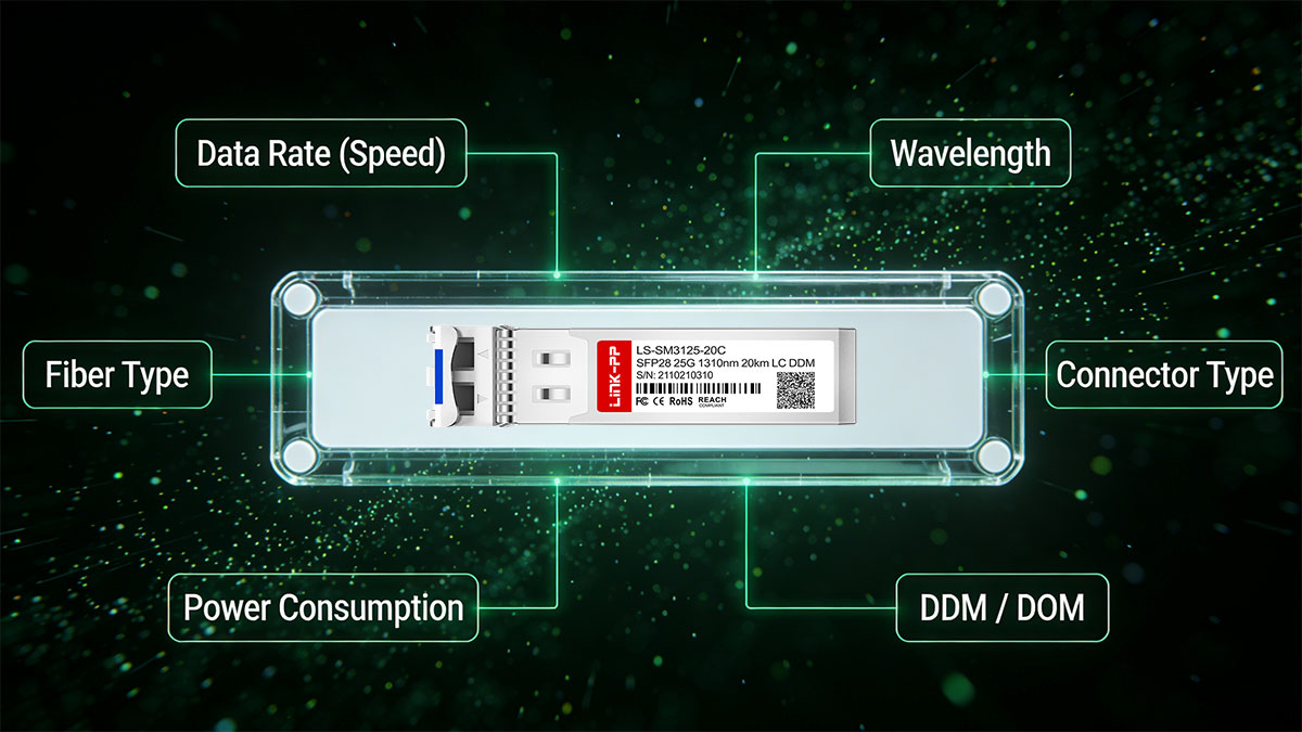
Data Rate (Speed)
The data rate defines the maximum transmission speed supported by the SFP transceiver.
-
Common speeds: 1G, 10G, 25G
-
Must match the switch or router port capability
-
Higher-speed modules typically require tighter signal integrity control
A mismatch between port speed and transceiver data rate will result in link failure.
Wavelength
Wavelength refers to the optical signal’s operating frequency, measured in nanometers (nm).
| Wavelength (nm) |
Fiber Type |
Typical Application |
| 850nm |
Multi-mode fiber (MMF) |
Short-reach links in data centers and enterprise networks |
| 1310nm |
Single-mode fiber (SMF) |
Standard long-reach connections over single-mode fiber |
| 1550nm |
Single-mode fiber (SMF) |
Extended-reach and long-haul optical links |
Both ends of the link must use SFP transceivers operating at the same wavelength.
Transmission Distance (Reach)
Transmission distance indicates the maximum supported link length under standard conditions.
-
Short-reach: Tens to hundreds of meters
-
Long-reach: Several kilometers
-
Extended reach: 40 km and beyond
Distance ratings assume compliant fiber type, connector quality, and acceptable optical loss.
Fiber Type and Connector
SFP transceivers are designed for specific fiber types and connector interfaces.
Fiber Type
Connector Type
Using incorrect fiber or connectors can significantly degrade signal quality.
Optical Power and Receiver Sensitivity
These two parameters define the optical link budget.
Proper link budget calculation ensures the signal remains within the acceptable operating range.
Digital Diagnostic Monitoring (DDM / DOM)
Many modern SFP transceivers support Digital Diagnostic Monitoring (DDM), also known as DOM.
DDM allows real-time monitoring of:
-
Module temperature
-
Supply voltage
-
Transmit optical power
-
Receive optical power
This feature is essential for proactive network maintenance and fault diagnosis.
Operating Temperature Range
SFP transceivers are rated for specific operating environments.
Temperature rating should match the deployment environment to avoid premature failure.
Power Consumption
Power consumption affects both thermal performance and port density.
Excessive power consumption may lead to thermal issues in high-density switches.
Compliance and Standards
SFP transceivers must comply with relevant industry standards.
-
MSA (Multi-Source Agreement) compliance
-
IEEE Ethernet standards (e.g., 1000BASE-X, 10GBASE-SR)
-
Safety and EMC certifications
Standards compliance ensures interoperability and long-term availability.
Compatibility and Coding
Although SFP transceivers follow MSA standards, vendor compatibility can vary.
This specification is frequently overlooked but critical during procurement.
Summary: Key SFP Transceiver Specifications at a Glance
| Specification |
Typical Values |
Engineering Notes |
| Data Rate |
1G, 10G, 25G |
Must match switch port capability; speed mismatch causes link failure |
| Wavelength |
850 nm, 1310 nm, 1550 nm |
Both ends must operate at the same wavelength |
| Transmission Distance |
100 m – 80 km |
Depends on fiber type, optical budget, and connector quality |
| Fiber Type |
MMF (OM1–OM4), SMF (OS1/OS2) |
MMF for short reach, SMF for long reach |
| Connector Type |
LC, RJ45 (copper) |
LC is standard for optical SFPs |
| Transmit Power |
–9 to +3 dBm (typical) |
Higher power supports longer reach but increases noise risk |
| Receiver Sensitivity |
–6 to –24 dBm (typical) |
Defines minimum detectable signal level |
| Link Budget |
8–30 dB (varies by type) |
Critical for loss calculation and stability |
| DDM / DOM |
Supported on most optical SFPs |
Enables real-time health monitoring |
| Operating Temperature |
0–70°C / –40–85°C |
Choose industrial grade for harsh environments |
| Power Consumption |
~0.5–1.5 W |
Impacts thermal design and port density |
| Standards Compliance |
MSA, IEEE 802.3 |
Ensures interoperability |
| Vendor Compatibility |
Platform-dependent |
EEPROM coding may be required |
In summary, engineers should always verify:
-
Data rate and wavelength
-
Fiber type and transmission distance
-
Optical power and receiver sensitivity
-
DDM support and temperature rating
-
Power consumption and platform compatibility
A clear understanding of these specifications reduces deployment risks and simplifies network design decisions.
✅ How to Choose the Right SFP Transceiver
Choosing the right SFP transceiver is not just about speed or distance—it requires a system-level evaluation of network requirements, hardware compatibility, and long-term scalability. The following step-by-step framework helps eliminate guesswork and reduces deployment risk.
Step 1: Confirm Network Equipment Compatibility
Start by verifying the switch, router, or NIC requirements.
-
Check supported SFP types and data rates
-
Review vendor documentation for compatibility restrictions
-
Identify whether third-party transceivers are supported
Even MSA-compliant modules may fail if the platform enforces vendor-specific coding.
Step 2: Define the Required Data Rate
Select an SFP transceiver that matches the port speed.
-
1G for legacy or access networks
-
10G for aggregation and data center uplinks
-
25G for high-density, modern infrastructure
Avoid over-specifying speed, as it increases cost without performance benefit.
Step 3: Choose the Correct Fiber Type
Fiber infrastructure directly determines SFP selection.
-
Existing MMF → short-reach optical SFPs
-
Long-distance or campus links → SMF-based SFPs
-
Copper cabling → RJ45 SFP transceivers
Replacing fiber later is significantly more expensive than selecting the correct SFP upfront.
Step 4: Match Transmission Distance to Link Length
Always select an SFP with a rated distance equal to or slightly greater than the actual link length.
-
Short links: Avoid excessive optical power
-
Long links: Ensure sufficient link budget
-
Consider attenuation from connectors and splices
Overpowered transceivers on short links may require optical attenuators.
Step 5: Verify Wavelength Consistency
Both ends of the link must use matching wavelengths.
For duplex links, ensure both transceivers are symmetrical.
Step 6: Evaluate Environmental Conditions
Deployment environment affects module reliability.
Temperature mismatch is a common cause of premature transceiver failure.
Step 7: Consider Power Consumption and Port Density
High-density switches require careful power and thermal planning.
Lower power modules improve overall system stability.
Step 8: Decide on Monitoring and Diagnostics Needs
For enterprise and carrier networks, diagnostic visibility is essential.
This step significantly reduces operational downtime.
Step 9: Balance Cost, Reliability, and Scalability
The lowest-cost option is not always the best choice.
-
Prioritize tested interoperability
-
Ensure supply chain stability
-
Consider future network upgrades
A well-chosen SFP transceiver minimizes total cost of ownership over time.
Decision Checklist: Choosing the Right SFP Transceiver
Before finalizing your selection, confirm:
-
✔ Port speed and supported SFP type
-
✔ Fiber infrastructure and link distance
-
✔ Wavelength and optical budget
-
✔ Environmental and power requirements
-
✔ Compatibility and diagnostics support
Following this checklist helps ensure a smooth deployment and reliable network performance.
✅ Common SFP Compatibility and Deployment Issues
Despite standardization, SFP transceivers are one of the most common sources of link issues in Ethernet and fiber networks. Many problems stem from compatibility assumptions, configuration mismatches, or deployment oversights.
The following sections address the most frequently searched SFP-related compatibility and deployment questions.
Can SFP Modules Be Used in SFP+ Ports?
In many cases, yes—but with limitations.
-
Most SFP+ ports are backward compatible with 1G SFP modules
-
The port will operate at the SFP’s lower speed (1G)
-
Not all switches support mixed-speed operation on SFP+ ports
However, some platforms disable 1G SFP support via firmware or hardware design. Always verify platform documentation before deployment.
Why an SFP Transceiver Link Is Not Working
An SFP link failure is rarely caused by the module alone. Common root causes include:
① Speed or Port Configuration Mismatch
② Wavelength or Fiber Mismatch
③ Polarity or Connector Issues
④ Optical Power Outside Acceptable Range
Checking DDM/DOM diagnostics often reveals the issue quickly.
Third-Party SFP Compatibility Considerations
Third-party SFP transceivers are widely used, but compatibility depends on platform behavior.
Vendor Lock and EEPROM Coding
Firmware and Software Version Dependencies
Testing and Validation
Selecting well-tested 3rd-party SFP reduces risk without sacrificing cost efficiency.
Best Practices to Avoid SFP Deployment Issues
To minimize compatibility and deployment problems:
-
Validate compatibility before large-scale procurement
-
Match speed, wavelength, and fiber type precisely
-
Use DDM-capable SFPs for monitoring
-
Clean fiber connectors before installation
-
Document platform firmware versions
Following these best practices significantly reduces troubleshooting time and network downtime.
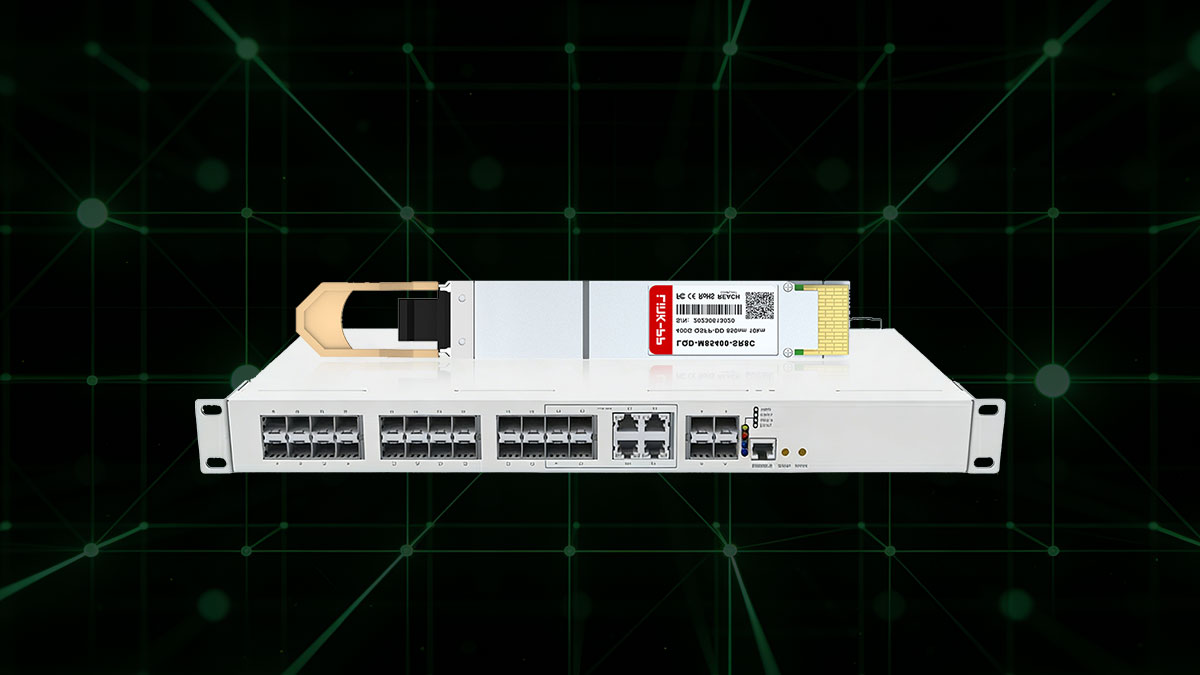
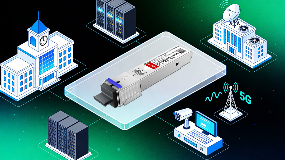
✅ Typical Applications of SFP Transceivers
SFP transceivers are widely adopted across modern network infrastructures due to their flexibility, scalability, and standardized form factor. Their ability to support different speeds, distances, and media types makes them suitable for a broad range of applications.
Below are the most common deployment scenarios where SFP transceivers play a critical role.
SFP Transceivers for Data Centers
In data center environments, SFP transceivers are primarily used for high-density, short- to medium-range connectivity.
Typical use cases include:
-
Top-of-rack (ToR) to aggregation switch links
-
Server and storage network interconnections
-
East–west traffic within data halls
Data centers prioritize:
-
Low latency and signal stability
-
High port density with efficient power usage
-
Compatibility across multi-vendor switching platforms
Short-reach optical SFPs are often favored for their reliability and ease of cable management.
Enterprise and Campus Networks
Enterprise and campus networks rely on SFP transceivers to support scalable and flexible network expansion.
Common applications include:
-
Access switch uplinks to distribution layers
-
Inter-building fiber links across campuses
-
Backbone connections between network closets
Key requirements in enterprise deployments are:
-
Cost-effective scalability
-
Simple maintenance and monitoring
-
Support for both legacy and modern infrastructure
SFP transceivers enable gradual network upgrades without full hardware replacement.
Telecom, FTTx, and Industrial Ethernet
In telecom and industrial environments, SFP transceivers are used in mission-critical and long-distance applications.
Typical scenarios include:
-
Metro and access networks
-
Fiber-to-the-home (FTTx) infrastructure
-
Industrial Ethernet and outdoor installations
These deployments demand:
-
Extended transmission distances
-
Wide operating temperature ranges
-
High reliability under harsh conditions
SFP transceivers designed for telecom and industrial use support continuous operation and strict performance requirements.
Why SFP Transceivers Remain a Core Networking Component
Across all application types, SFP transceivers offer:
-
Modular and hot-pluggable design
-
Media flexibility (fiber and copper)
-
Long-term ecosystem support
Their adaptability ensures continued relevance in evolving network architectures.
✅Summary: Choosing the Right SFP Transceiver
Selecting the right SFP transceiver requires more than matching speed or distance. It involves a holistic evaluation of network architecture, hardware compatibility, operating environment, and long-term scalability.
Throughout this guide, we covered:
-
What an SFP transceiver is and how it works
-
Key technical specifications engineers must evaluate
-
Common compatibility and deployment issues to avoid
-
Typical application scenarios across data centers, enterprises, and telecom networks
By aligning these factors with real-world deployment requirements, network professionals can significantly reduce integration risks and improve overall network reliability.
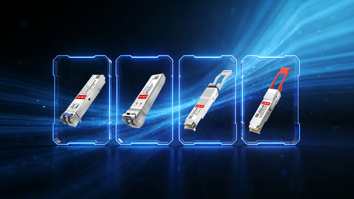
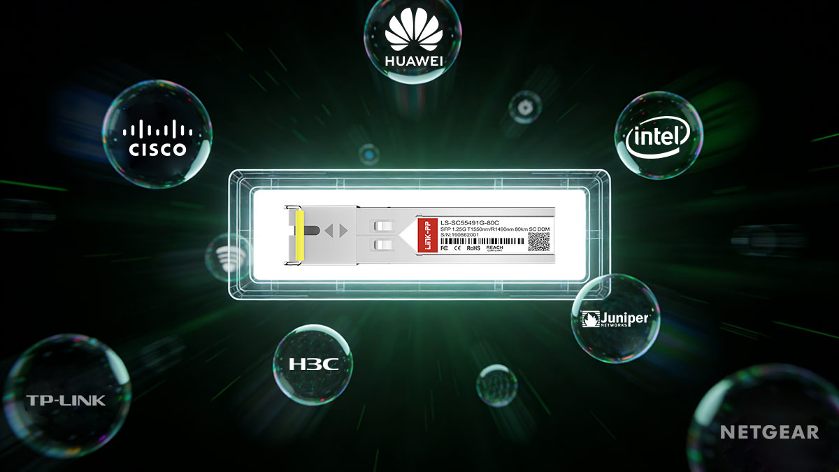
LINK-PP SFP Transceiver Solutions
LINK-PP provides a comprehensive portfolio of high-quality SFP transceiver solutions designed for enterprise, data center, and telecom applications.
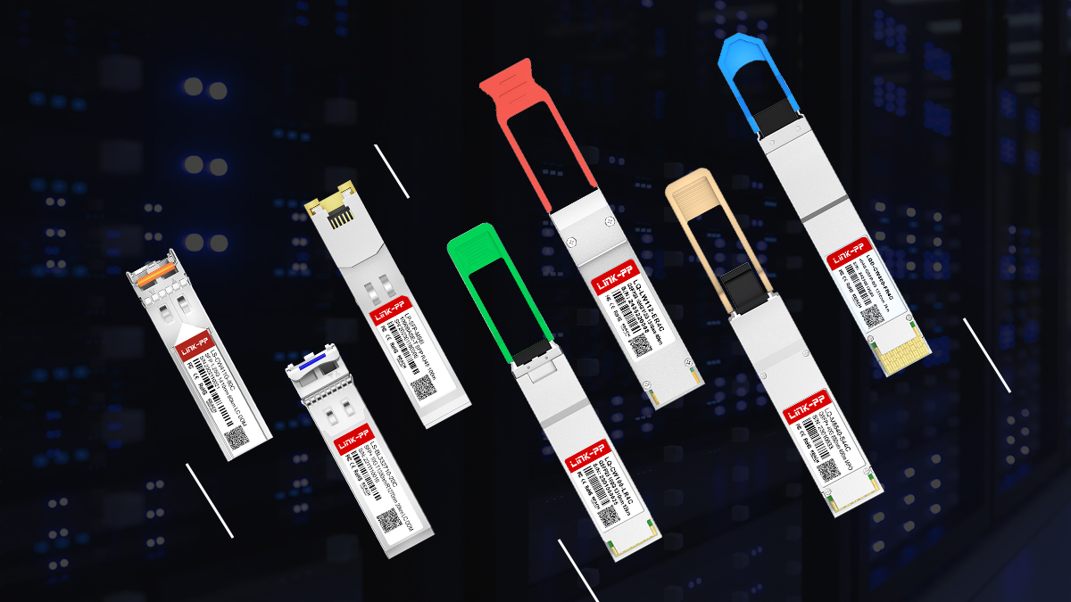
Key advantages include:
-
Wide product coverage across SFP, SFP+, and higher-speed form factors
-
MSA-compliant design for broad interoperability
-
Extensive compatibility testing with major switching and routing platforms
-
Stable performance and reliable supply for long-term network deployments
LINK-PP SFP transceivers are engineered to support multi-vendor environments, helping organizations achieve cost-effective scalability without compromising performance or compatibility.
Make the Right Choice with Confidence
Whether you are upgrading an existing network or building new infrastructure, choosing the right SFP transceiver is critical to network success. Partnering with a trusted transceiver manufacturer ensures consistent quality, validated compatibility, and dependable technical support.
Explore LINK-PP’s full range of SFP transceiver solutions to find the right fit for your network requirements and deployment scenarios.