Small Form-factor Pluggable (SFP) modules are a core building block of modern network infrastructure, enabling flexible fiber or copper connectivity across switches, routers, and network interface cards. From enterprise access networks to large-scale data centers, SFP modules allow network engineers to adapt port speeds, transmission distances, and media types without replacing core hardware.
However, despite their hot-pluggable design and standardized form factor, incorrect SFP installation remains a common cause of link failures, degraded optical performance, and even permanent port damage. Issues such as port incompatibility, improper handling, fiber polarity errors, or incomplete insertion can prevent a link from coming up—or lead to intermittent faults that are difficult to diagnose.
This guide provides a clear, step-by-step explanation of how to install an SFP module correctly, based on real-world deployment practices. It covers critical preparation checks, proper insertion techniques, hot-swap and safety considerations, common installation mistakes, and practical troubleshooting steps when an SFP link does not work as expected.
All instructions are vendor-neutral and apply broadly to industry-standard SFP and SFP+ modules used on popular networking platforms, including Cisco, Juniper, HPE, Arista, and fully MSA-compliant third-party transceivers. Whether you are installing an SFP module for the first time or validating an existing connection, this article is designed to help you achieve stable, compliant, and reliable network links.
What You Will Learn from This Guide
By reading this article, you will learn:
-
How to insert an SFP transceiver correctly into a switch or router without damaging the port or module.
-
The correct installation order for SFP modules and fiber or copper cables to ensure proper link negotiation.
-
Whether SFP modules can be hot swapped safely, and under what conditions hot insertion or removal is recommended.
-
How to remove or disconnect an SFP module properly using different latch mechanisms (pull tab, bail latch, or slide latch).
-
Common SFP installation mistakes that often cause link failures, port errors, or unstable connections.
-
What to check when an SFP module is not working after installation, including compatibility, cabling, and link status indicators.
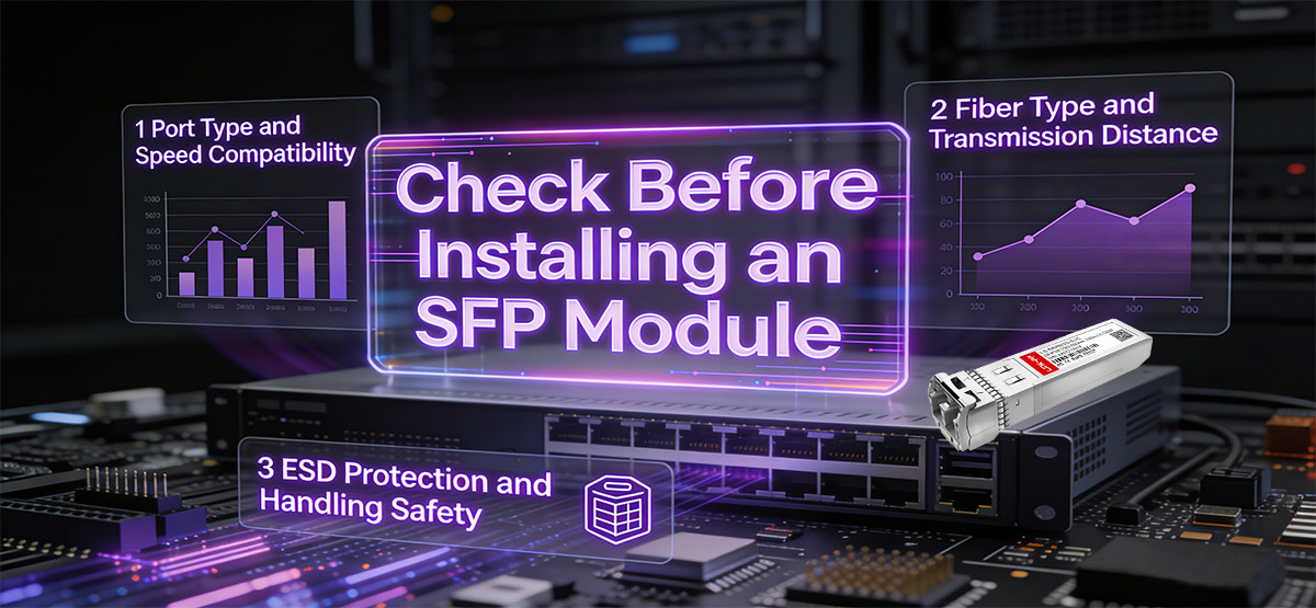
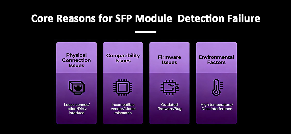
▶️ What Should You Check Before Installing an SFP Module?
Before installing an SFP module, verify port compatibility, supported speed, fiber type, and ESD protection.
Ensure the device supports the correct SFP or SFP+ standard, match the module speed to the port, use the appropriate fiber for the transmission distance, and prevent static discharge to avoid hardware damage.
Proper preparation helps prevent link failures, optical signal issues, and unnecessary hardware faults. Before inserting an SFP transceiver, check the following key factors.
Port Type Compatibility
Confirm that the network device supports the correct form factor.
-
SFP and SFP+ are not physically or electrically interchangeable
-
Installing an SFP module into an SFP+-only port may result in the port staying down
-
Always verify the switch or router port specifications in the hardware documentation
Speed Matching
The SFP module speed must be supported by the port.
-
1G SFP modules should not be installed in fixed-speed 10G-only ports
-
Some devices support auto-negotiation or speed downshifting, but this is platform-specific
-
Mismatched speeds often cause the link to remain down with no clear error
Fiber Type and Distance
Use the correct fiber type based on the optical module.
-
SR (Short Reach) modules → Multimode fiber (MMF)
-
LR / ER (Long / Extended Reach) modules → Single-mode fiber (SMF)
-
Using the wrong fiber type can lead to excessive loss or no link at all
ESD Protection
Static electricity can damage sensitive optical components.
-
Wear an ESD wrist strap when available
-
At minimum, discharge static electricity by touching a grounded metal surface
-
Handle the module by its edges and avoid touching the electrical contacts
Tip: Keep the dust cap on the SFP module and fiber connector until you are ready to connect the cable. This helps prevent contamination and signal degradation.
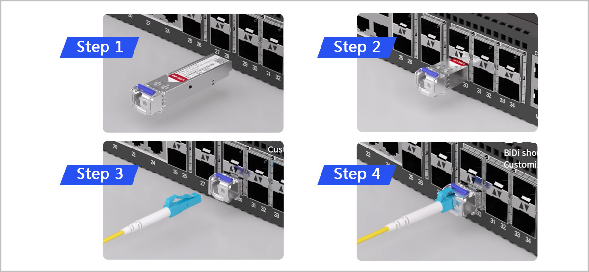
▶️ How to Install an SFP Module Step by Step
The following step-by-step instructions are based on proven installation practices used by network engineers to ensure reliable connectivity and hardware safety.
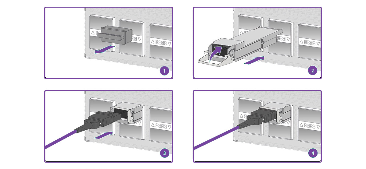
Step 1: Identify the Correct SFP Orientation
Before insertion, check the orientation of the SFP transceiver.
-
The label side usually faces upward, but this can vary by device
-
The latch mechanism (bail latch, pull tab, or slide latch) should be accessible
-
Never force the module if resistance is felt
Correct orientation ensures the electrical contacts align properly with the port connector.
Step 2: Insert the SFP Module Gently into the Port
Carefully slide the SFP module into the SFP or SFP+ port.
-
Insert the module straight and evenly
-
Apply light, steady pressure
-
You should feel a click or firm stop when fully seated
Forcing the module may damage the port cage or internal connector.
Step 3: Secure the Latch Mechanism
Once inserted, confirm the latch is in its default, locked position.
A properly secured latch prevents accidental loosening or signal interruption.
Step 4: Verify Physical Installation
Visually inspect the installed module.
-
The SFP should sit flush with the port faceplate
-
There should be no visible gap between the module and the device
-
The latch should be stable and not partially open
If the module is not fully seated, remove it and reinsert carefully.
Step 5: Connect the Fiber Cable
After the SFP module is securely installed, you can connect the fiber cable to the transceiver.
Removing Dust Caps and Cleaning Connectors
Before making any fiber connection, remove the dust caps from both the SFP module and the fiber connectors.
-
Keep dust caps in place until the moment of connection
-
Avoid touching the fiber end face with bare fingers
-
If contamination is suspected, use a proper fiber cleaning tool or lint-free wipe with isopropyl alcohol
Even microscopic dust particles can cause signal loss or prevent the optical link from coming up.
Ensuring Correct Tx and Rx Polarity
Correct transmit (Tx) and receive (Rx) polarity is essential for establishing an optical link.
-
The Tx port on one SFP module must connect to the Rx port on the remote module
-
Duplex LC fiber cables are typically crossed internally, but polarity can vary by cable type
-
If the link LED remains off, reversed Tx/Rx polarity is a common cause
When troubleshooting, swapping the two LC connectors is a simple and safe first step.
Best Practice:
Always install the SFP module first, verify it is fully seated, and only then connect the fiber cable. This reduces mechanical stress on the connector and helps prevent alignment issues.
Step 6: Check Link Status
Once the fiber cable is connected, verify that the link is operational.
-
Check the port LED indicators on the switch or router
-
Use the device CLI or management interface to confirm link status
-
If the link remains down, proceed to troubleshooting steps later in this guide
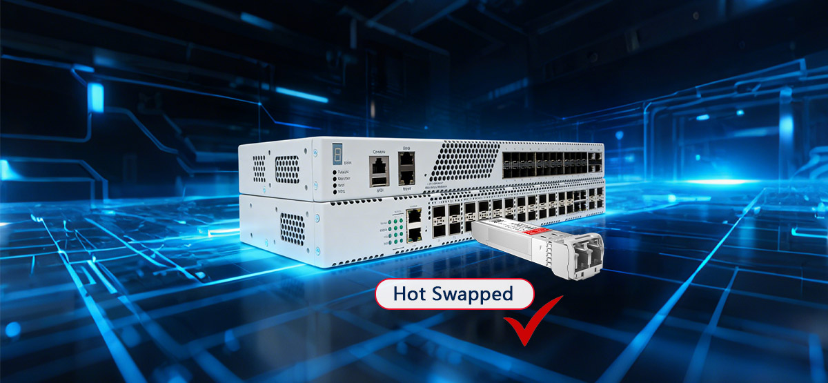
▶️ Can SFP Modules Be Hot Swapped Safely?
Yes, most SFP modules are designed to support hot swapping, meaning they can be inserted or removed while the device is powered on.
However, hot-swap capability does not eliminate operational risks. Improper procedures may cause optical contamination, port damage, transient link errors, or unexpected alarms on the network device.
Hot-Swap and Safety Considerations
Hot swapping is generally safe when performed correctly and infrequently, especially during maintenance or replacement tasks. Follow these best practices to minimize risk.
Recommended Best Practices
✔ Disconnect the fiber cable before removing the SFP module
This prevents mechanical stress on the connector and reduces the chance of contaminating the optical interface.
✔ Use the latch or pull tab to release the module
Always disengage the bail latch or pull tab before sliding the module out of the port.
✔ Allow the device a few seconds to recognize changes
Some switches may take a short time to update link status or log events after insertion or removal.
✔ Handle modules by the housing only
Avoid touching electrical contacts or optical interfaces.
✔ Replace dust caps immediately after removal
This protects the optical surfaces from dust and moisture during storage or transport.
What to Avoid During Hot Swapping
✖ Do not pull the SFP module out by the fiber cable
This can damage both the cable and the transceiver interface.
✖ Do not hot swap repeatedly in a short time
Frequent insertion and removal can wear the port cage and lead to intermittent contact issues.
✖ Do not mix hot swapping with live troubleshooting unless necessary
Uncontrolled changes can trigger port flaps, link renegotiation, or system logs that complicate diagnosis.
Laser Safety Warning
SFP fiber modules use laser transmitters that may be active even if the link appears down.
-
Never look directly into an optical port
-
Never look into the end of a fiber cable connected to an SFP module
-
Always assume the laser is enabled unless the module has been fully removed and the device powered off
Following proper hot-swap procedures helps maintain hardware integrity, ensures optical safety, and prevents avoidable network disruptions.
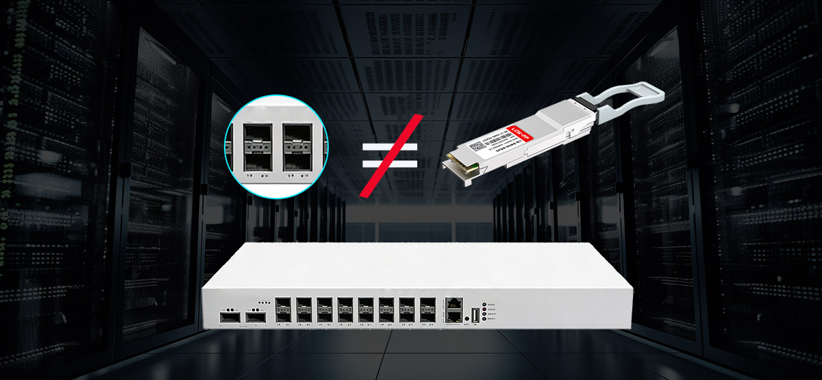
▶️ SFP vs. SFP+: Compatibility Checks Before Installation
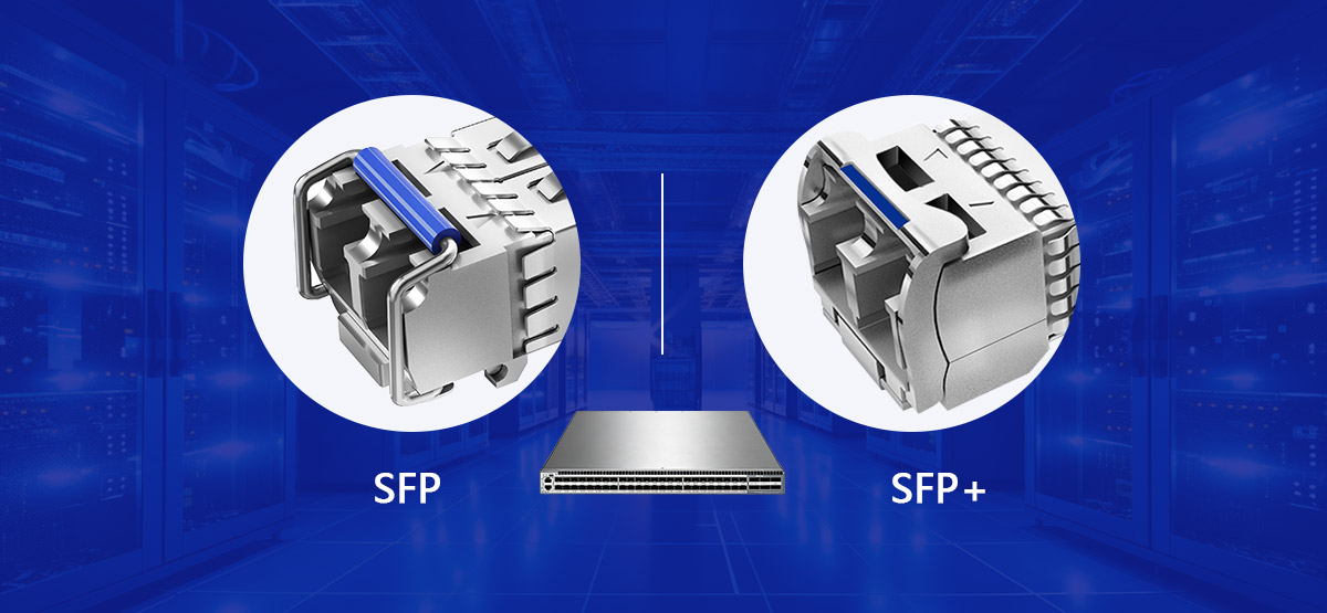
Differences Between SFP and SFP+ Modules
What is the difference between SFP and SFP+ during installation?
Although SFP and SFP+ modules share the same physical form factor and appear identical, they are designed for different electrical and signaling requirements. This distinction is critical during installation.
| Feature |
SFP |
SFP+ |
| Typical Speed |
1G |
10G |
| Physical Size |
Same |
Same |
| Electrical Interface |
Different |
Different |
| Interchangeable |
❌ |
❌ |
Even though they look identical, SFP and SFP+ modules are not interchangeable.
Installing the wrong module type may result in link failure, port errors, or the module not being detected at all.
Common Compatibility Issues in Switch Ports
Compatibility problems often occur when module capabilities do not match the port design or configuration.
Common scenarios include:
-
Installing a 1G SFP in a fixed-speed 10G-only port
Some switch ports are designed exclusively for SFP+ operation and do not support 1G fallback.
-
Assuming physical fit equals compatibility
While an SFP module may physically slide into an SFP+ cage, the electrical interface may not be supported.
-
Port configuration mismatches
Certain platforms require manual speed or port-mode configuration for proper detection.
-
Using unsupported third-party modules
Some vendors enforce compatibility checks that can prevent unapproved transceivers from operating.
Installation Best Practices for SFP and SFP+ Modules
To avoid compatibility-related installation issues:
-
Confirm whether the port supports SFP, SFP+, or dual-rate operation
-
Check the switch or router hardware documentation before installation
-
Ensure the module speed matches the port’s supported data rates
-
Verify compatibility when using third-party or vendor-neutral modules
Understanding the differences between SFP and SFP+ before installation helps prevent unnecessary troubleshooting and ensures a stable, reliable network link.
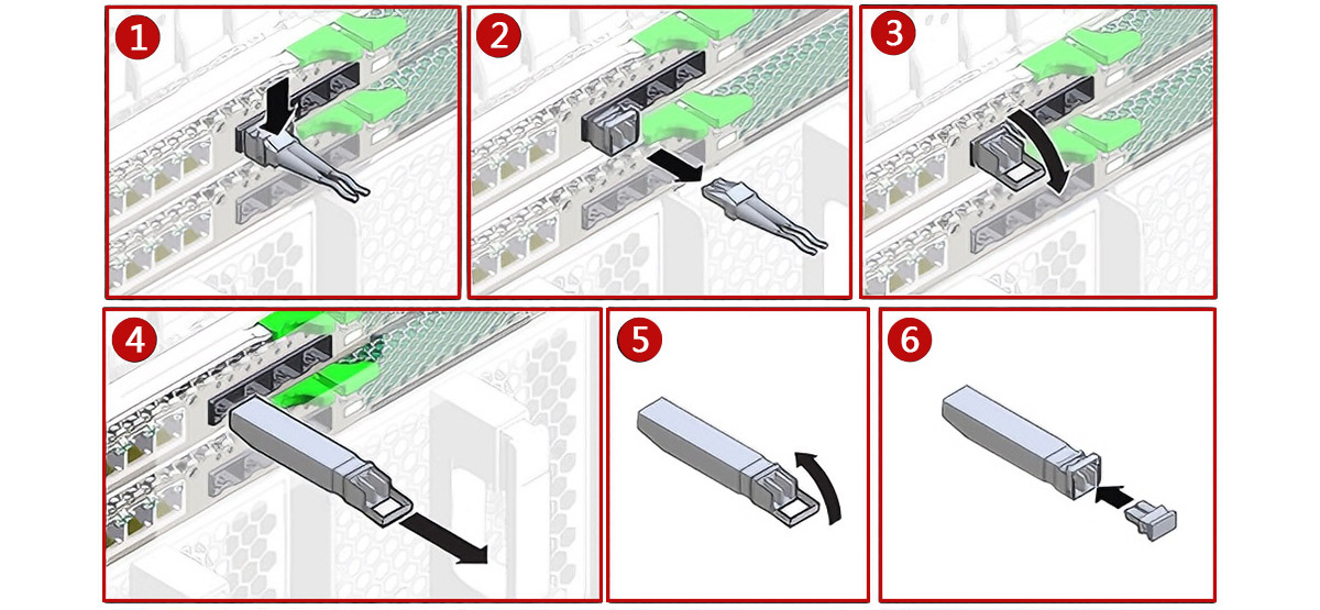
▶️ How to Remove or Disconnect an SFP Module
Proper removal of an SFP Transceiver is just as important as correct installation. Following the correct sequence helps prevent connector damage, optical contamination, and accidental link disruption.
How to Disconnect an SFP Cable Safely
Before removing the SFP module itself, always disconnect the attached fiber cable.
-
Gently pull the LC connector straight out of the SFP port
-
Avoid twisting or bending the fiber during removal
-
Do not apply force to the cable jacket
Once disconnected, keep the fiber connector clean and protected to avoid contamination.
Steps to Remove an SFP Module from a Switch
Follow these steps to remove an SFP module safely from a powered or unpowered device.
Step 1: Disconnect the Fiber Cable First
Always remove the fiber cable before removing the SFP module to eliminate stress on the optical interface.
Step 2: Release the Latch Mechanism
Pull the bail latch, release tab, or slide latch—depending on the module design—to unlock it from the port cage.
Step 3: Gently Slide the SFP Module Out
Hold the module by its housing and slide it straight out using steady, even pressure. Do not force the module.
Step 4: Immediately Install a Dust Cap
Place a dust cap on the SFP module as soon as it is removed to protect the optical interface from dust and moisture.
Best Practice Reminder
-
Store removed SFP modules in anti-static packaging
-
Avoid placing exposed modules on unprotected surfaces
-
If the module will be reused, keep both the module and fiber connectors capped
Correct removal procedures help extend the lifespan of both the SFP module and the switch port, while reducing the risk of future link issues.
▶️ Common SFP Installation Mistakes
Many SFP-related link failures are caused not by defective hardware, but by simple installation mistakes. Understanding these common errors can save significant troubleshooting time and help ensure stable optical performance.
Fiber and Polarity Errors
Incorrect fiber selection or polarity is one of the most frequent causes of link issues.
-
Installing the wrong fiber type (SMF vs MMF)
Single-mode SFP modules (LR, ER) must be used with single-mode fiber, while multimode SFP modules (SR) require multimode fiber. Mixing them often results in no link or severe signal loss.
-
Incorrect Tx/Rx polarity
The transmit (Tx) port on one SFP must connect to the receive (Rx) port on the opposite end. Reversed polarity will prevent the link from coming up, even if everything else is correct.
Module and Port Mismatch Issues
Physical fit does not guarantee electrical or logical compatibility.
-
Mixing SFP and SFP+ ports
Installing a 1G SFP module into a fixed-speed 10G-only SFP+ port may result in the module not being detected.
-
Assuming all ports auto-negotiate speed
Many SFP and SFP+ ports operate at fixed speeds and require a module that matches the port’s supported data rate.
-
Using unsupported modules
Some switches enforce vendor compatibility checks that can block third-party transceivers.
Handling and Cleanliness Problems
Improper handling can degrade optical performance even when the correct components are used.
-
Forgetting to clean fiber connectors
Dust or oil contamination on the fiber end face can cause insertion loss or intermittent link failures.
-
Touching optical interfaces
Fingerprints on optical surfaces are difficult to remove and can permanently affect signal quality.
-
Leaving ports or modules uncapped
Exposed optical interfaces quickly accumulate dust, increasing the risk of future link issues.
Best Practice Summary
To avoid these common mistakes:
-
Match the SFP module type, speed, and fiber type correctly
-
Verify Tx/Rx polarity during fiber connection
-
Handle modules and fibers carefully and keep interfaces clean
-
Confirm port capabilities before installation
Avoiding these pitfalls helps ensure a reliable SFP installation and minimizes unnecessary troubleshooting.
▶️ Why Is My SFP Module Not Working After Installation?
What should you check if the SFP link is down?
If an SFP module is installed but the link does not come up, the issue is often related to installation, compatibility, or cabling rather than a faulty transceiver. The checks below help isolate the problem efficiently.
How to Diagnose Installation-Related Issues
Start with the most common and easily verifiable causes.
-
Confirm the SFP module is fully seated
Remove and reinsert the fiber module, ensuring it clicks firmly into place and sits flush with the port faceplate.
-
Verify fiber polarity (Tx ↔ Rx)
Ensure the transmit port on one end is connected to the receive port on the other. Reversed polarity is a frequent cause of link failure.
-
Check for port link indicators
Observe the switch or router LEDs. No port light usually indicates a physical, compatibility, or polarity issue rather than a configuration problem.
-
Confirm fiber type and distance
Verify that multimode or single-mode fiber matches the SFP type and that the link distance is within the module’s supported range.
-
Inspect and clean fiber connectors
Remove dust caps, clean the connectors if necessary, and reconnect carefully.
SFP Link Down or No Port Light: Common Causes
If the port LED remains off, consider the following possibilities:
-
The module type or speed is not supported by the port
-
The fiber cable is damaged or incorrectly connected
-
Tx/Rx polarity is reversed
-
The SFP module is not recognized due to compatibility restrictions
-
The module or port is defective
Checking these factors systematically helps avoid unnecessary module replacement.
When to Reseat or Replace the SFP Module
If basic checks do not restore the link:
-
Reseat the module
Remove the SFP, wait a few seconds, and reinsert it to ensure proper electrical contact.
-
Test with a known-good module or cable
Swapping components is one of the fastest ways to isolate faulty hardware.
-
Replace the module
If the link still does not come up after reseating and verification, the SFP module may be defective or incompatible.
Practical Troubleshooting Tip
Always troubleshoot one change at a time. Making multiple changes simultaneously can make it difficult to identify the root cause of the issue.
▶️ Frequently Asked Questions About SFP Module Installation
Q1: Is It Safe to Hot Plug an SFP Module?
Yes, most SFP modules are designed to support hot plugging, meaning they can be inserted or removed while the switch or router is powered on.
However, safe hot plugging requires correct handling:
-
Always disconnect the fiber cable before removing the module
-
Use the latch or pull tab instead of pulling on the cable
-
Avoid frequent insertion and removal, which can wear the port
Hot plugging is safe when done properly, but careless handling can cause port damage or link instability.
Q2: Why Does My SFP Module Not Work After Installation?
If an SFP module does not work after installation, the most common causes are installation or compatibility issues rather than hardware failure.
You should check:
-
Whether the SFP module is fully seated in the port
-
Tx and Rx fiber polarity (Tx ↔ Rx)
-
Fiber type compatibility (single-mode vs multimode)
-
Port speed support (SFP vs SFP+)
-
Cleanliness of fiber connectors
In many cases, reseating the module or correcting fiber polarity resolves the issue.
Q3: Can I Install an SFP Module in Any Switch?
No, an SFP module cannot be installed in any switch without verification.
Before installation, confirm that:
-
The switch port supports SFP or SFP+, not just physical fit
-
The port supports the module’s data rate (1G or 10G)
-
The switch firmware allows the specific module type
-
Third-party modules are supported or permitted by the vendor
Even though SFP modules share a standard form factor, electrical and firmware compatibility still matter.
Q4: Do I Need to Power Off the Switch Before Installing an SFP Module?
In most cases, powering off the switch is not required, as SFP modules support hot swapping.
That said, for critical production environments, planned maintenance windows and controlled changes are recommended to avoid unexpected link disruptions.
Q5: What Is the Correct Order: Install the SFP or Connect the Fiber First?
The correct order is:
-
Install the SFP module into the port
-
Ensure it is fully seated and locked
-
Then connect the fiber cable
Connecting the fiber before inserting the module can place stress on the connector and increase the risk of contamination.
Q6: How Long Do SFP Modules Typically Last?
SFP modules are designed for long-term operation and often last many years under normal conditions.
Their lifespan depends on operating temperature, insertion cycles, and handling practices. Proper installation and minimal hot swapping help extend service life.
▶️ Conclusion: Installing SFP Modules Correctly for Reliable Network Links
Correct SFP module installation is a foundational skill for building and maintaining stable fiber networks in enterprise and data center environments. While SFP transceivers are designed to be flexible and hot-swappable, reliable operation depends on proper preparation, correct installation order, and careful handling.
In this guide, we covered the full installation lifecycle—from pre-installation checks and step-by-step insertion, to fiber connection, hot-swap safety, compatibility between SFP and SFP+, safe removal procedures, and systematic troubleshooting. Many common link failures can be avoided by verifying fiber type, port compatibility, Tx/Rx polarity, and connector cleanliness before assuming a module is defective.
By following these best practices, network engineers and operators can reduce downtime, protect hardware, and ensure consistent optical performance across their infrastructure.
Key Takeaways
-
Always confirm port compatibility and module type (SFP vs SFP+) before installation
-
Install the SFP module first, then connect the fiber cable
-
Verify Tx/Rx polarity and keep optical interfaces clean
-
Hot swapping is generally safe, but only when done correctly
-
Most “link down” issues are caused by installation or compatibility errors, not faulty modules
A structured, methodical approach to SFP installation saves time and prevents unnecessary troubleshooting.
Choose Reliable, Compatible SFP Modules
If you are deploying or maintaining fiber links and need cost-effective, vendor-neutral SFP modules with broad compatibility, consider high-quality third-party options designed for enterprise and data center use.
👉 Explore LINK-PP SFP Optical Transceivers
LINK-PP offers a wide range of SFP and SFP+ modules compatible with major networking platforms, helping you build reliable networks without the premium cost of OEM optics.