
10GBASE-LR is a 10-gigabit Ethernet optical standard that operates at 1310 nm over single-mode fiber (SMF), supporting link distances of up to 10 km. It is typically implemented using SFP+ transceivers and defined under IEEE 802.3 specifications. 10G-LR module has become one of the most widely deployed 10G optical standards in enterprise backbones, metro access networks, and data center interconnects.
In practical deployments, 10GBASE-LR is most commonly implemented using SFP+ transceiver module, typically with LC duplex connectors and optional Digital Diagnostic Monitoring (DDM/DOM) support. These modules follow industry multi-source agreements (MSAs), enabling broad interoperability across switches, routers, and network interface cards—provided that optical budgets, fiber type, and compatibility constraints are properly understood.
Despite its widespread use, 10GBASE-LR is often misunderstood. Common questions include:
-
What exactly does “LR” mean in Ethernet standards?
-
Why is 1310 nm used instead of 850 nm or 1550 nm?
-
How is the 10 km distance determined in real-world fiber links?
-
What optical power budget is required, and how should it be calculated?
-
When should 10GBASE-LR be chosen over alternatives such as 10GBASE-SR or 10GBASE-ER?
This article provides a clear, engineer-oriented explanation of 10GBASE-LR, focusing on verified standards, real optical specifications, and deployment-level considerations rather than marketing claims. You will learn how 10GBASE-LR works, what parameters actually matter in production networks, and how to evaluate whether it is the right solution for your specific fiber infrastructure.
By the end of this guide, readers should be able to:
-
Accurately define 10GBASE-LR in technical and procurement contexts
-
Understand its optical characteristics, distance limits, and fiber requirements
-
Interpret SFP+ LR specifications and DDM readings with confidence
-
Avoid common deployment and compatibility pitfalls in 10G single-mode links
? 10GBASE-LR Overview – 1310 nm Single-Mode 10 km Standard
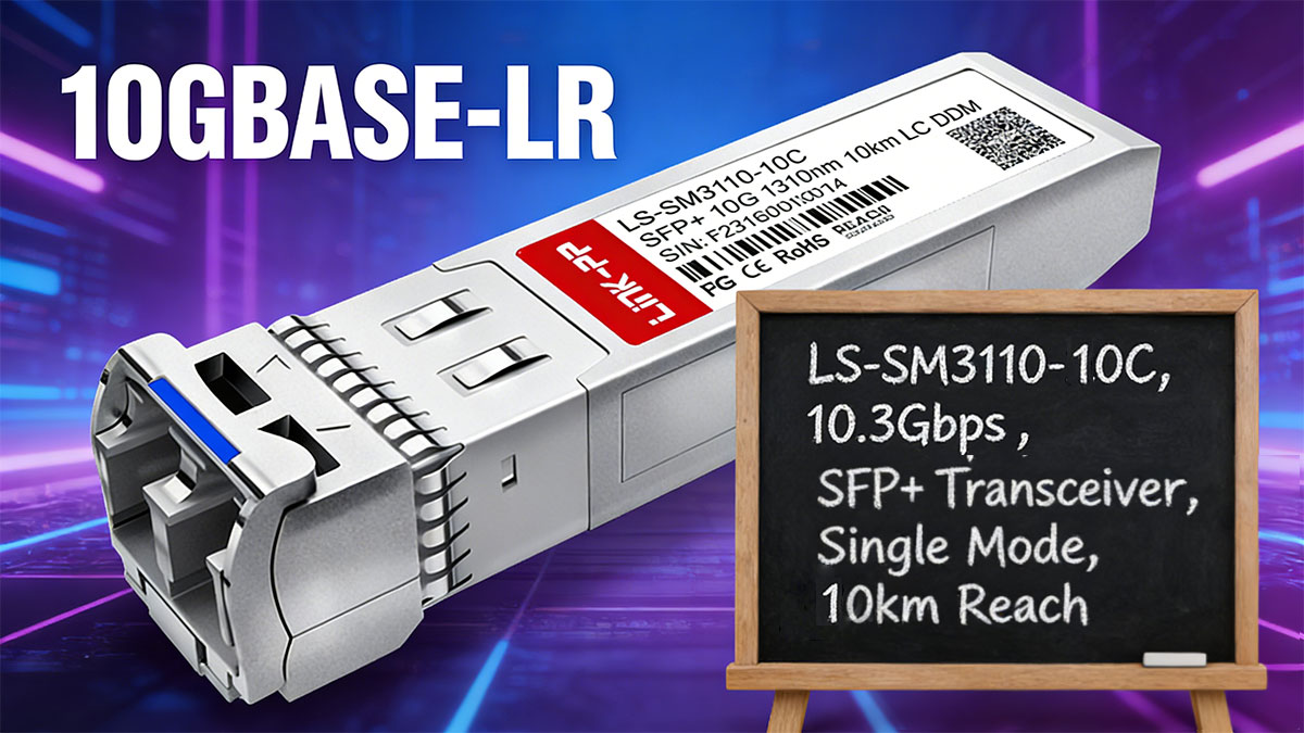
10GBASE-LR is a long-reach 10-gigabit Ethernet physical layer standard defined under IEEE 802.3ae. The “LR” designation stands for Long Reach, meaning it is engineered to reliably transmit 10 Gbit/s Ethernet signals over single-mode fiber (SMF) for distances up to 10 kilometers. This standard uses a 1310 nm wavelength, which balances chromatic dispersion, fiber attenuation, and cost-effectiveness for metro, campus, and enterprise backbone networks.
In practical deployment, 10G-LR is most commonly implemented using SFP+ transceiver modules, which conform to SFF-8431 electrical specifications and often support SFF-8472 Digital Diagnostic Monitoring (DDM/DOM) for real-time telemetry of temperature, supply voltage, transmit power, and receive power. Modules typically use LC duplex connectors to interface with single-mode fiber, ensuring polarity compliance and low insertion loss.
Key technical characteristics of 10GBASE-LR include:
-
Data rate: 10.3125 Gbit/s (64b/66b encoding)
-
Fiber type: 9/125 µm single-mode (G.652 compliant)
-
Maximum reach: 10 km under standard attenuation (~0.35 dB/km at 1310 nm) and connector/splice loss allowances
-
Transmitter type: DFB laser (Distributed Feedback), optimized for single-mode fiber
-
Receiver sensitivity: typically −14 to −15 dBm
-
Optical power budget: approximately 8–11 dB, depending on fiber quality and connector/splice losses
This standard is widely used in data center interconnects, enterprise backbones, and metro fiber networks where single-mode fiber availability and moderate distances make 10GBASE-LR the preferred solution over short-reach (10GBASE-SR) or extended-reach (10GBASE-ER) alternatives. Correct planning of optical power budget, fiber path, and connector quality is critical to maintain link reliability and avoid signal loss or errors.
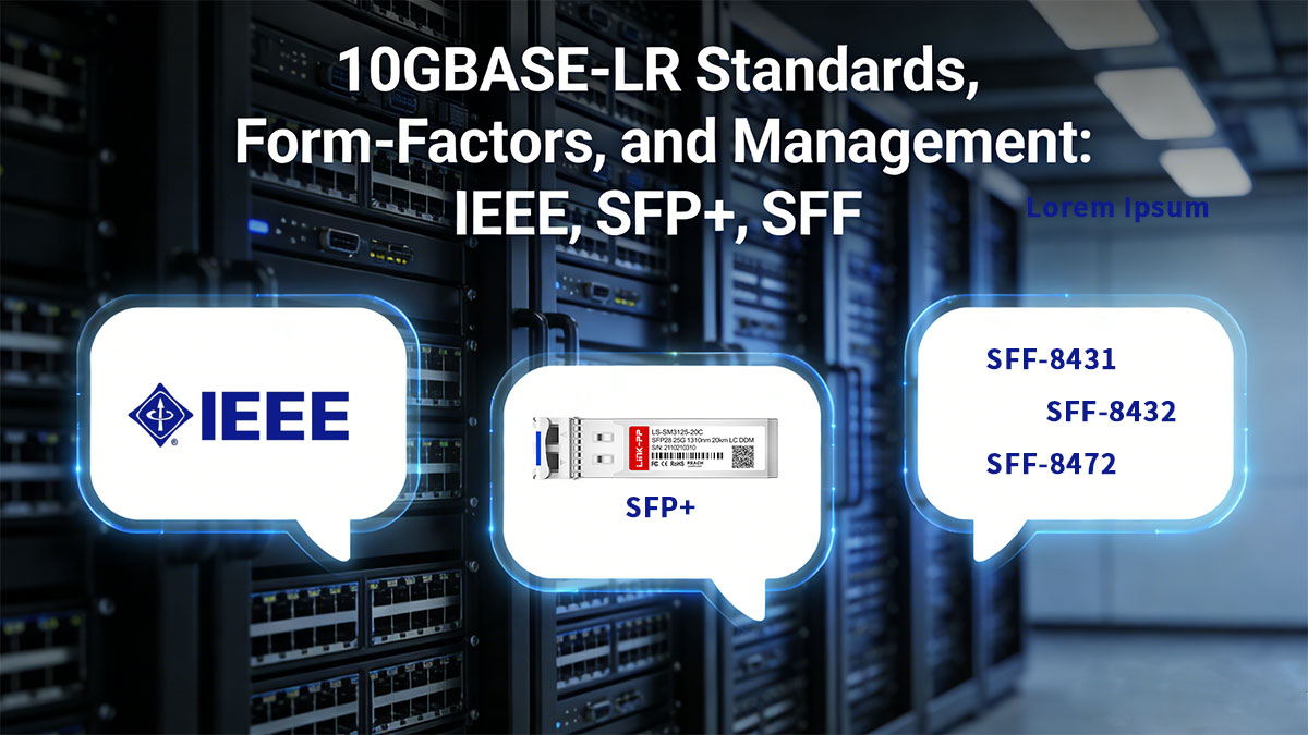
? 10GBASE-LR Standards, Form-Factors, and Management: IEEE, SFP+, SFF
IEEE 802.3ae Overview
10GBASE-LR is defined by the IEEE 802.3ae standard, which specifies the physical layer (PHY) requirements for 10-Gigabit Ethernet transmission over single-mode fiber (SMF). The standard establishes key parameters including the typical operating wavelength of 1310 nm, transmission reach of up to 10 km, and the use of 64b/66b encoding to maintain efficient high-speed data transport.
IEEE 802.3ae also defines transmitter output power ranges, receiver sensitivity, and link budget requirements to ensure predictable optical performance. By adhering to these specifications, network equipment from multiple vendors can interoperate within the same infrastructure, enabling scalable deployment of long-reach 10GbE links in enterprise, campus, and data center environments.
SFP+ Form Factor and SFF-8431 Electrical Specification
Most commercial 10GBASE-LR implementations are delivered in the SFP+ (Small Form-Factor Pluggable Plus) package, which is governed by the SFF-8431 specification. This standard defines the high-speed serial electrical interface between the host system and the transceiver, including signal integrity requirements for 10 Gb/s operation.
SFF-8431 also specifies mechanical dimensions, connector interface, and thermal operating characteristics, ensuring consistent module compatibility across switches, routers, and network interface cards. The compact and hot-swappable design of SFP+ modules allows network operators to upgrade or replace optics without service interruption, improving deployment flexibility and simplifying maintenance in high-density networking environments.
SFF-8472 DDM/DOM Monitoring Capabilities
Many 10G SFP+ LR modules support Digital Diagnostic Monitoring (DDM), also referred to as Digital Optical Monitoring (DOM), as defined in the SFF-8472 standard. This functionality provides real-time access to critical operating parameters such as transmit optical power, receive optical power, module temperature, supply voltage, and laser bias current.
These diagnostics enable network engineers to verify link margins, detect gradual signal degradation, and identify environmental or hardware-related issues before they cause service disruption. DDM/DOM capability is particularly valuable in long-distance single-mode deployments where subtle power fluctuations or thermal variations can impact overall link stability and performance.
LC Connector and Fiber Interface Requirements
10GBASE-LR transceivers typically use LC duplex optical connectors, which are optimized for single-mode fiber (SMF) applications and high-density port environments. The LC interface provides low insertion loss, reliable alignment, and consistent polarity, all of which are critical for maintaining stable optical transmission over long distances.
Proper fiber management practices—including connector cleanliness, correct mating, and inspection for contamination—are essential to achieving the specified 10 km reach and preserving the designed optical budget. Even minor contamination or connector damage can introduce additional loss, potentially reducing link margin and impacting overall network reliability.
By combining IEEE standard compliance, SFP+ form factor, and DDM/DOM management, network engineers can deploy SFP+ LR links with confidence, achieving long-reach, high-speed connectivity over single-mode fiber while minimizing the risk of downtime or signal degradation.
? 10GBASE-LR Optical Specifications: Wavelength, T/R Ranges, Power Budget
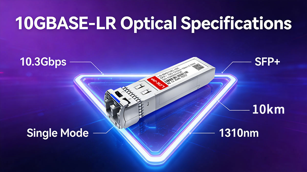
10GBASE-LR operates at a nominal wavelength of 1310 nm over single-mode fiber (SMF, 9/125 µm, G.652 compliant), providing a standardized maximum link distance of 10 kilometers. This wavelength was chosen to optimize the tradeoff between chromatic dispersion and fiber attenuation, ensuring reliable high-speed transmission for enterprise, metro, and data center interconnects.
The optical characteristics of SFP 10G LR are defined in IEEE 802.3ae and include both transmitter and receiver specifications:
-
Transmitter (Tx) Power: Typically ranges from −8 dBm to +0.5 dBm, depending on the SFP+ module and manufacturer. The transmitter uses a Distributed Feedback (DFB) laser, which provides stable single-mode output at 1310 nm.
-
Receiver (Rx) Sensitivity: Standard 10GBASE-LR receivers can reliably detect signals down to −14 to −15 dBm, ensuring adequate link margin over 10 km of standard single-mode fiber.
-
Receiver Overload: The upper limit of received optical power is usually around −1 dBm, beyond which the receiver may saturate.
-
Dispersion Tolerance: 10G-LR modules tolerate chromatic dispersion up to 1.0 ns/nm, covering standard SMF deployments over the specified distance.
Optical power budget—the difference between minimum Tx and maximum Rx sensitivity—is typically 8–11 dB, depending on fiber quality, connector insertion loss, and splice count. This margin ensures reliable performance under real-world conditions and allows engineers to account for aging fiber, temperature variations, and additional interconnect losses.
Connector and form factor considerations are also critical:
-
LC Duplex Connectors: Provide low insertion loss (~0.3 dB per connector) and compact footprint for high-density installations.
-
Polarity Compliance: Correct A/B fiber alignment is essential to maintain signal integrity.
-
Module Types: SFP+ transceivers with DDM/DOM support allow real-time monitoring of Tx power, Rx power, voltage, and temperature, providing actionable insights into link performance.
By adhering to these specifications, network engineers can ensure that 10GBASE-LR links achieve predictable performance, minimize signal degradation, and maintain interoperability across devices from different vendors. Proper understanding of wavelength selection, transmitter/receiver ranges, and optical budgets is crucial when planning long-reach 10G Ethernet links.
How to Calculate an Optical Power Budget for 10GBASE-LR
Calculating an optical power budget is a critical step when designing or validating a 10G-LR link. The optical power budget determines whether a 10 km single-mode fiber link will reliably transmit 10 Gbit/s signals without signal degradation or errors.
The optical power budget is defined as the difference between the minimum transmitter (Tx) power and the minimum receiver (Rx) sensitivity, minus any losses introduced by the fiber path, connectors, and splices:
$$ Optical\ Power\ Budget\ (dB) = Minimum\ Transmitter\ Power\ (Tx) - Minimum\ Receiver\ Sensitivity\ (Rx) - Link\ Losses $$
Where Link Losses include:
-
Fiber attenuation: Typically 0.35 dB/km at 1310 nm for G.652 single-mode fiber.
-
Connector insertion loss: ~0.3–0.5 dB per LC connector.
-
Splice loss: ~0.1–0.3 dB per splice.
-
Contingency margin: 1–2 dB to account for aging, temperature, or unforeseen losses.
Worked Example
Assume a typical 10GBASE-LR SFP+ module:
| Parameter |
Value |
| Tx minimum power |
−6 dBm |
| Rx sensitivity |
−15 dBm |
| Fiber length |
10 km |
| Fiber attenuation |
0.35 dB/km |
| Connector loss |
0.5 dB × 2 |
| Splice loss |
0.2 dB × 2 |
| Contingency margin |
1.5 dB |
Step 1: Calculate fiber loss
$$ \begin{aligned} Fiber\ Loss &= Fiber\ Length \times Fiber\ Attenuation \\ &= 10\ km \times 0.35\ dB/km \\ &= 3.5\ dB \end{aligned} $$
Step 2: Add connector and splice losses
$$ \begin{aligned} Connector\ Loss &= 0.5 \times 2 = 1.0\ dB \\ Splice\ Loss &= 0.2 \times 2 = 0.4\ dB \end{aligned} $$
Step 3: Add contingency margin
$$ \begin{aligned} Total\ Losses &= Fiber\ Loss + Connector\ Loss + Splice\ Loss + Contingency\ Margin \\ &= 3.5 + 1.0 + 0.4 + 1.5 \\ &= 6.4\ dB \end{aligned} $$
Step 4: Calculate optical power budget margin
$$ \begin{aligned} Available\ Margin &= Tx(min) - Rx(min) \\ &= -6 - (-15) \\ &= 9\ dB \end{aligned} $$
Step 5: Verify link feasibility
$$ \begin{aligned} Margin\ After\ Losses &= Available\ Margin - Total\ Losses \\ &= 9 - 6.4 \\ &= 2.6\ dB \end{aligned} $$
✅ Conclusion: The 10 km link is feasible with a 2.6 dB margin, providing adequate reserve to accommodate aging, temperature variation, and minor fiber loss increases.
Best Practices
-
Always use the worst-case Tx and Rx values from SFP module datasheet to ensure reliable performance.
-
Include connector, splice, and contingency margins; never assume ideal conditions.
-
For critical links, verify using a power meter or OTDR before production deployment.
-
Monitor link health with DDM/DOM to detect signal degradation over time.
? 10GBASE-LR Deployment Tips: Fiber, Connectors, Cleanliness, and DDM Checks
Successfully deploying a 10G LR link requires careful attention to fiber type, connectors, cleanliness, and monitoring, in addition to verifying optical power budgets. Following best practices ensures predictable performance and long-term reliability for enterprise backbones, metro links, and data center interconnects.
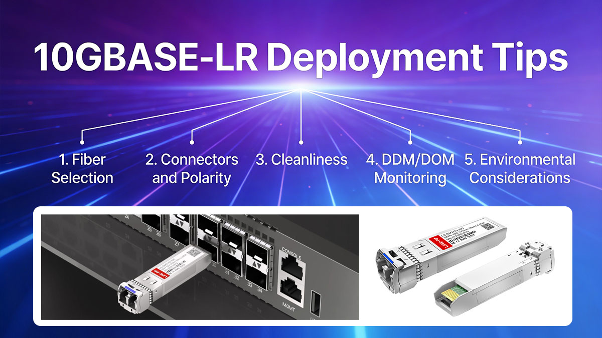
1. Fiber Selection
-
Single-Mode Fiber (SMF, 9/125 µm, G.652 compliant) is required for 10GBASE-LR. Avoid multimode fiber (OM3/OM4) for LR links, as it will cause signal loss and unreliable performance.
-
Fiber Quality: Use low-attenuation, well-certified fiber. Typical attenuation at 1310 nm is 0.35 dB/km, but older or degraded fiber may have higher loss.
-
Path Planning: Minimize bends and sharp turns to prevent micro-bending losses. Maintain recommended bend radius for the fiber type.
2. Connectors and Polarity
-
LC Duplex Connectors are standard for LR SFP+ modules. Ensure A/B polarity alignment to maintain transmit/receive paths.
-
Connector Loss: Typically ~0.3–0.5 dB per connector; always account for this in the optical power budget.
-
Polarity Verification: Use a fiber continuity tester or OTDR to verify correct polarity before powering up the link.
3. Cleanliness
-
Clean connectors and patch cords using lint-free wipes or specialized fiber cleaning tools. Dust or oil can cause signal degradation or total loss.
-
Inspect Ferrules under a fiber microscope if available, especially in data center deployments where high density increases contamination risk.
-
Avoid Touching Fiber Ends: Even fingerprints can reduce optical power by 0.5–1 dB per connector.
4. DDM/DOM Monitoring
-
Digital Diagnostic Monitoring (DDM) or Digital Optical Monitoring (DOM) provides real-time telemetry on Tx power, Rx power, supply voltage, and temperature.
-
Operational Checks: Verify that Tx/Rx power levels are within the module’s specified range. Identify potential fiber attenuation, connector contamination, or misalignment early.
-
Routine Monitoring: Schedule periodic checks to detect slow degradation due to fiber aging or environmental changes.
5. Environmental Considerations
-
Temperature: 10Gb SFP+ modules are rated for specific temperature ranges (typically 0°C to +70°C for commercial grade). Excess heat can reduce transmitter power or module lifespan.
-
Mechanical Stress: Avoid tension or twisting on fiber runs that could induce micro-bending losses or connector misalignment.
-
Redundancy Planning: For critical links, consider parallel fiber paths or redundant SFP+ modules to ensure continuity during maintenance or failure.
Summary
Adhering to these deployment best practices ensures 10GBASE-LR links achieve predictable performance, maintain optical budget margins, and remain interoperable across vendor devices. Proper fiber selection, connector management, cleanliness, and active DDM monitoring are essential for reliable long-reach 10G Ethernet deployment.
? Interoperability and Vendor Considerations of 10GBASE-LR Modules
When deploying 10G-LR links, ensuring interoperability across devices and vendors is crucial. While the standard IEEE 802.3ae defines the physical layer specifications, practical network deployment often encounters compatibility challenges due to vendor-specific coding, module firmware, and proprietary locking mechanisms. Understanding these factors is essential for reliable long-reach 10G Ethernet performance.

1. Vendor Compatibility
-
SFP+ Modules Across Vendors: Most SFP+ modules conform to the SFF-8431/8432 and SFF-8472 standards, allowing physical and electrical interoperability.
-
Switch and Router Compatibility: Although physical compatibility exists, some vendors require vendor-verified modules for full operational support, including DDM telemetry.
-
Cross-Vendor Testing: Before deployment, test SFP+ 10G modules on the target switch or router to verify link stability, optical power readings, and temperature behavior.
2. Vendor Lock and Module Coding
-
Vendor Lock: Some OEMs implement module authentication codes or firmware locks that prevent non-certified modules from operating or enabling advanced features.
-
Module Coding: Modules include vendor-specific identifiers in their EEPROM, which can affect power reporting, DOM data accuracy, and compatibility warnings on switches.
-
Mitigation: Use vendor-approved third-party modules or verify the module against official compatibility lists provided by the switch/router manufacturer. For enterprise and data center environments, maintaining homogeneous module sourcing reduces operational risk.
3. Best Practices for Interoperability
-
Check IEEE and MSA Compliance: Ensure SFP+ modules meet SFF-8431, SFF-8432, and SFF-8472 standards.
-
Verify Link Operation Before Production: Confirm that the 10GBASE-LR link achieves expected Tx/Rx power margins and DDM telemetry readings.
-
Maintain a Module Inventory Log: Track vendor, part number, firmware version, and deployment location to simplify troubleshooting and replacements.
-
Use Redundancy Where Critical: Deploy parallel modules or redundant paths in high-availability environments to mitigate potential vendor-specific failures.
4. Operational Considerations
-
Firmware Updates: Occasionally, vendor firmware updates may change SFP+ recognition or power thresholds. Always test updated firmware in a lab environment before network-wide deployment.
-
Documentation: Maintain reference to vendor datasheets and IEEE specifications to support troubleshooting and compliance auditing.
-
Vendor Collaboration: Engage with vendors for support on interoperability issues, especially in multi-vendor environments where long-reach links traverse diverse infrastructure.
Deployment Tips
For 10GBASE-LR links, understanding vendor compatibility, module coding, and potential OEM lock mechanisms is essential to ensure stable, predictable network performance. Proactive testing, compliance verification, and careful module sourcing help maintain interoperability across switches, routers, and 10GBASE-T SFP+ modules, minimizing link failures and operational disruptions.
? Troubleshooting 10GBASE-LR Links: Tests, DOM Values, OTDR vs. Power Meter
Even with proper planning and deployment, 10GBASE-LR links may experience performance issues due to fiber degradation, connector contamination, module aging, or improper configuration. Systematic troubleshooting ensures link reliability and minimal downtime.
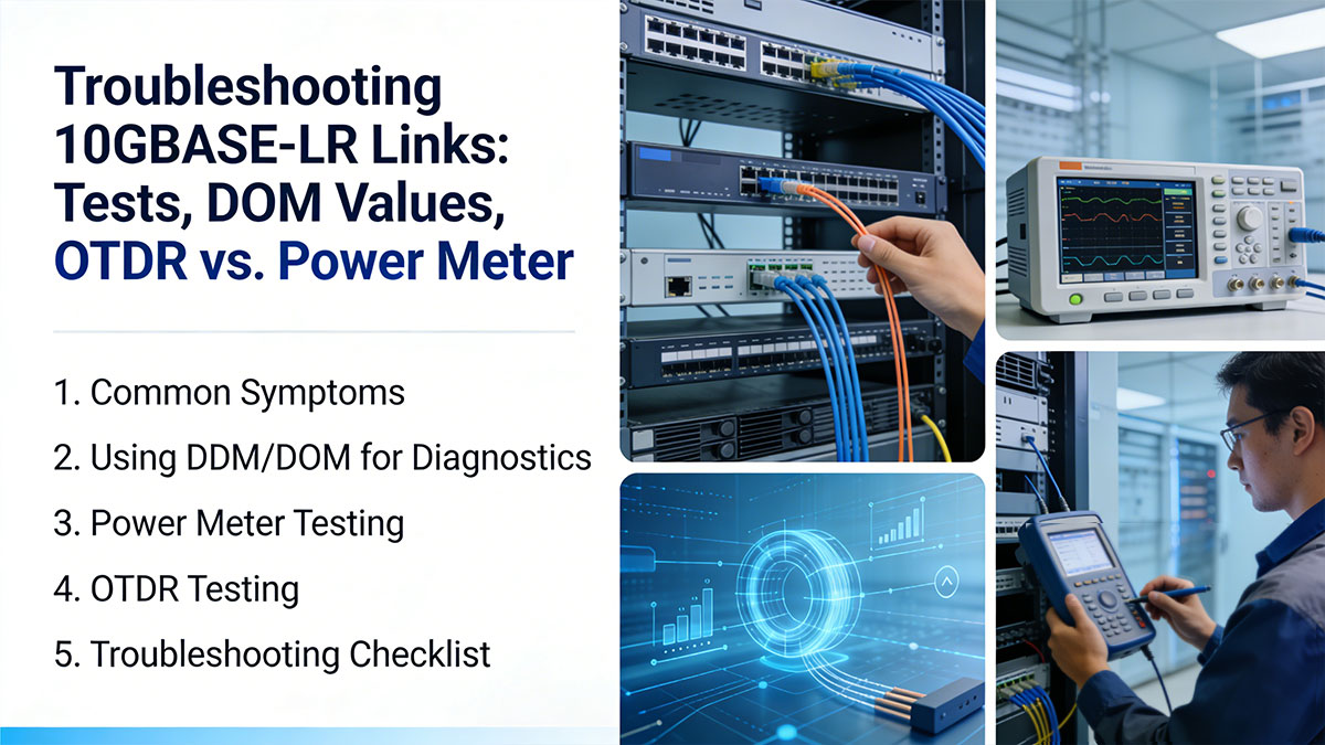
1. Common Symptoms
-
Link Down / No Signal: LOS (Loss of Signal) or LOF (Loss of Frame) alarms.
-
Intermittent Connectivity: Fluctuating DOM readings or sporadic errors.
-
Reduced Throughput: High error rates due to optical power below receiver sensitivity.
2. Using DDM/DOM for Diagnostics
Digital Diagnostic Monitoring (DDM/DOM) provides real-time telemetry to identify optical issues:
-
Tx Power: Verify the module is transmitting within its specification (typically −8 to +0.5 dBm for 10GBASE-LR).
-
Rx Power: Ensure received optical power exceeds the minimum receiver sensitivity (−14 to −15 dBm).
-
Voltage & Temperature: Abnormal readings may indicate module overheating or power supply problems.
Tip: Always compare DOM values with the SFP+ datasheet specifications to determine if readings are within acceptable limits.
3. Power Meter Testing
A fiber optic power meter measures absolute optical power at the receiver. Steps:
-
Disconnect the fiber from the transceiver output.
-
Connect the power meter to measure received optical power.
-
Compare measured values with the link budget.
This is useful for verifying fiber loss, connector loss, and overall link margin.
4. OTDR Testing
Optical Time-Domain Reflectometer (OTDR) testing can locate fiber faults, splices, or macrobends.
-
OTDR is more useful for long links (>1 km) or complex fiber paths.
-
For short 10 km 10GBASE-LR links, OTDR may overestimate losses due to dead zone limitations, so it should be complemented with power meter measurements.
5. Troubleshooting Checklist
-
Inspect connectors and clean if necessary.
-
Verify fiber type (SMF, G.652) and correct polarity.
-
Check DDM/DOM telemetry against module specs.
-
Measure optical power using a calibrated power meter.
-
If issues persist, use OTDR to locate fiber faults.
-
Replace SFP+ LR module with a verified compatible unit to rule out module failure.
Effective troubleshooting of 10GBASE-LR links combines real-time DDM/DOM monitoring, power meter measurements, and OTDR testing. By systematically checking optical power, connector integrity, and fiber path quality, engineers can quickly identify and resolve link issues, ensuring stable 10 km 1310 nm single-mode connections.
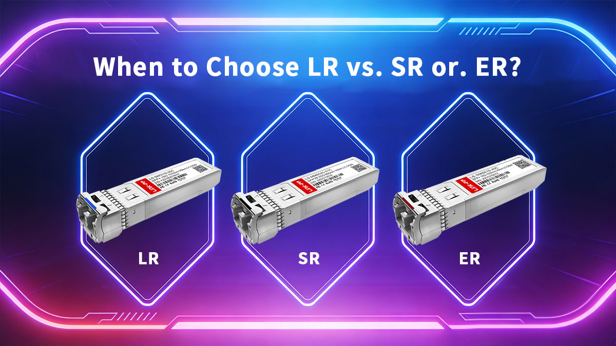
? When to Choose LR vs. SR or. ER: Distance, Fiber, and Budget
Choosing the right 10G optical standard—whether 10G-LR, 10G-SR, or 10G-ER—depends on several factors including link distance, fiber type, optical budget, and cost considerations. Understanding the tradeoffs ensures optimal performance, interoperability, and long-term reliability.
1. Overview of 10GBASE Standards
| Standard |
Wavelength |
Fiber Type |
Max Distance |
Typical Use Case |
| 10GBASE-SR |
850 nm |
Multimode (OM3/OM4) |
300 m / 400 m |
Short-reach data center connections |
| 10GBASE-LR |
1310 nm |
Single-mode (G.652) |
10 km |
Enterprise backbones, metro links, inter-building |
| 10GBASE-ER |
1550 nm |
Single-mode (G.652) |
40 km |
Long-reach metro and campus links |
Note: SR is cost-effective for short distances, while ER provides extended reach at higher cost and optical power requirements.
2. Decision Factors
Distance:
-
Use SR for links <400 m over multimode fiber.
-
Choose LR for distances up to 10 km over single-mode fiber.
-
Opt for ER when links exceed 10 km but do not require DWDM or optical amplification.
Fiber Type:
Optical Budget:
-
LR modules typically require a link power budget of 8–11 dB.
-
ER modules demand higher power budgets (up to 18 dB), considering fiber attenuation, connectors, and splices.
Cost and Availability:
-
SR modules are generally the least expensive.
-
LR offers a balance between cost and reach for enterprise and metro networks.
-
ER modules are more expensive due to higher transmitter power and stricter component tolerances.
3. Practical Decision Matrix
| Parameter |
SFP+ SR |
SFP+ LR |
SFP+ ER |
| Fiber |
OM3/OM4 |
SMF (G.652) |
SMF (G.652) |
| Max Distance |
300–400 m |
10 km |
40 km |
| Wavelength |
850 nm |
1310 nm |
1550 nm |
| Optical Budget |
Low |
Medium (8–11 dB) |
High (15–18 dB) |
| Typical Deployment |
Data centers |
Enterprise/metro |
Metro/campus long-reach |
| Module Cost |
Low |
Medium |
High |
4. Recommendations
-
Short-reach (<400 m, multimode): 10GBASE-SR is optimal.
-
Medium-reach (up to 10 km, single-mode): 10GBASE-LR is preferred.
-
Long-reach (>10 km, single-mode, metro/campus): Consider 10GBASE-ER.
Always verify link budget, fiber type, connector losses, and DDM/DOM telemetry before finalizing module selection. This ensures predictable performance and avoids unnecessary module replacements.
Choosing the correct 10GBASE standard requires balancing distance, fiber type, optical budget, and cost. 10G-LR is ideal for single-mode links up to 10 km, providing reliable performance for enterprise backbones and metro networks. SR and ER remain better suited for short-reach and extended-reach scenarios, respectively, based on physical and budget constraints.
? Summary of 10GBASE-LR Key Points
10GBASE-LR is a robust and widely deployed 10-gigabit Ethernet standard optimized for 1310 nm single-mode fiber links up to 10 km. By combining IEEE 802.3ae compliance, SFP+ form factor, and proper optical management, LR links provide reliable high-speed connectivity for enterprise backbones, metro networks, and inter-building connections.
Key Takeaways
-
Standards Matter: Ensure all modules conform to IEEE 802.3ae, SFF-8431/8432, and SFF-8472 (DDM/DOM) for interoperability and accurate telemetry.
-
Optical Specifications: 10GBASE-LR uses 1310 nm wavelength, DFB lasers, and supports optical power budgets of 8–11 dB, enabling 10 km links over standard G.652 SMF.
-
Deployment Best Practices: Focus on fiber quality, LC duplex connectors, polarity, cleanliness, and DDM/DOM monitoring to maintain link performance.
-
Troubleshooting Tools: Combine DDM/DOM readings, optical power meters, and OTDR testing to quickly identify and resolve link issues.
-
Vendor Considerations: Verify cross-vendor compatibility and account for module coding or OEM lock mechanisms to avoid unexpected failures.
-
Choosing the Right Standard: Use LR for single-mode 10 km links, SR for short-reach multimode connections, and ER for extended 40 km single-mode links.
For engineers and network planners seeking reliable, fully tested 10GBASE-LR SFP+ modules, explore our LINK-PP Official Store. All modules are IEEE 802.3ae compliant, with full DDM/DOM support, ensuring plug-and-play compatibility across switches, routers, and network interface cards.
Implementing 10GBASE-LR correctly ensures predictable long-reach 10 Gbit/s Ethernet performance, reduces troubleshooting time, and maximizes network uptime.


