
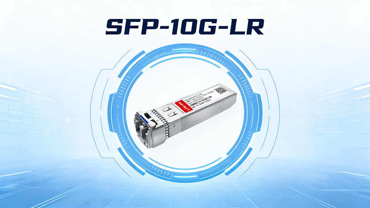
SFP-10G-LR Specifications: Optical, Electrical & Link Params provides a comprehensive, engineer-grade breakdown of the specification parameters that define the performance and interoperability of 10GBASE-LR SFP+ optical transceiver modules. These modules are widely used to deliver 10.3125 Gbps Ethernet over 1310 nm single-mode fiber (SMF) for distances up to 10 km, making them a foundational component in enterprise backbones, metro links, and data center interconnects.
Specifications are more than checkbox entries on a SFP+ datasheet: they determine whether a module will deliver predictable signal integrity, sufficient optical power margin, and reliable diagnostics across real-world deployment conditions. Accurate optical parameters (such as transmitter power and receiver sensitivity), electrical characteristics (such as supply voltage and signaling interface), and link parameters (such as fiber attenuation and connector loss) are essential to planning, deploying, and troubleshooting 10GBASE-LR links that meet performance and uptime targets.
This guide focuses on verified, standard-aligned specification values and interpretation, drawing from IEEE 802.3ae 10GBASE-LR, SFP+ multi-source agreements (MSAs), and common vendor datasheets. Rather than generic descriptions, you will find measurable values, explanation of why each parameter matters, and how these specifications relate to real optical link behavior and engineering decisions.
By the end of this article, you will be able to:
-
Define key SFP-10G-LR parameters and what they mean in practice
-
Understand how optical and electrical specifications impact link reach and reliability
-
Interpret DOM/DDM telemetry values and their role in operational health monitoring
-
Apply specification data to engineering tasks such as optical power budget calculations, module selection, and compatibility checks
Whether you are planning a network upgrade, validating a design, or troubleshooting a deployed link, this article equips you with accurate, verifiable, and operationally relevant specification insights.
The next section begins with an authoritative overview that positions SFP-10G-LR within the broader family of 10G optical standards and makes clear how optical, electrical, and link parameters work together to deliver performance.
⏩ SFP-10G-LR Overview: What the Spec Means
The SFP-10G-LR specification defines a standardized 10-gigabit Ethernet optical transceiver designed for 10GBASE-LR links over single-mode fiber (SMF). “LR” stands for Long Reach, indicating support for link distances up to 10 km under IEEE-defined optical and link budget constraints. In practical terms, this specification establishes the minimum and maximum optical, electrical, and link-level requirements that ensure predictable performance and multi-vendor interoperability.
At its core, the SFP-10G-LR spec combines three tightly coupled layers:
Optical Layer (What travels over the fiber)
10GBase-LR SFP+ Transceivers operate at a nominal wavelength of 1310 nm, chosen for its low chromatic dispersion and favorable attenuation characteristics in standard ITU-T G.652 single-mode fiber. The specification defines:
-
Transmitter output power range
-
Receiver sensitivity and overload limits
-
Optical extinction ratio and dispersion tolerance
These parameters collectively determine whether the optical signal can be transmitted, received, and decoded with an acceptable bit error rate (BER ≤ 10⁻¹²) across the full 10 km reach.
Electrical Layer (How the module interfaces with the host)
Electrically, SFP-10G-LR follows the SFP+ MSA form factor and signaling requirements, using high-speed serial electrical lanes between the module and the host PHY or MAC. The specification constrains:
This ensures the module can operate reliably across different switches, routers, and NICs without exceeding thermal or signal-integrity limits.
Link Definition (How everything works together)
Beyond individual parameters, the SFP-10G-LR specification defines a system-level optical link model. This includes assumptions for:
-
Fiber attenuation (≈ 0.4 dB/km at 1310 nm)
-
Connector and splice losses
-
Optical power budget margin
The result is a standardized deployment envelope where compliant modules from different vendors can be mixed, validated, and supported in production networks.
Why this specification matters
Understanding what the SFP-10G-LR spec actually defines helps engineers avoid common pitfalls—such as assuming all “10 km” modules behave identically or overlooking receiver overload risks on short links. The specification is not just a description of capability; it is a contract between the module, the host system, and the fiber plant that enables scalable, interoperable 10G Ethernet deployments.
In the next sections, we break down the optical, electrical, and link parameters in detail, explaining how each value is defined, why it exists, and how to apply it in real-world network design and validation.
⏩ Core Technical Specifications of SFP-10G-LR
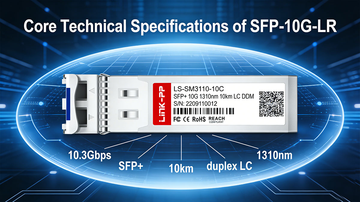
1. Optical Specifications of SFP-10G-LR (1310 nm SMF)
The optical specifications define how light is generated, transmitted, and received over single-mode fiber. For 10G-LR Module, these parameters are tightly aligned with IEEE 802.3 Clause 52 and form the foundation of the 10 km reach guarantee.
Operating Wavelength and Spectral Width
SFP-10G-LR operates at a nominal wavelength of 1310 nm, with an allowed range typically between 1260 nm and 1355 nm. This wavelength window minimizes chromatic dispersion on standard G.652 SMF and enables stable transmission without dispersion compensation at 10 Gbit/s.
Most compliant modules use Distributed Feedback DFB lasers, which provide:
Transmitter Optical Power
The specification defines both minimum and maximum launch power to balance reach and receiver safety:
| Parameter |
Typical Spec Range |
| Average Tx Power |
−6.0 to +0.5 dBm |
| Optical Modulation Amplitude (OMA) |
≥ −3.0 dBm |
| Extinction Ratio |
≥ 3.5 dB |
These limits ensure sufficient optical margin for 10 km links while preventing excessive power that could overload receivers on shorter fiber runs.
Receiver Sensitivity and Overload
On the receive side, the SFP-10G-LR specification defines two critical thresholds:
| Parameter |
Typical Spec |
| Receiver Sensitivity |
≤ −14.4 dBm |
| Receiver Overload |
≥ +0.5 dBm |
This wide receive window allows reliable operation across varying link losses and supports flexible deployment scenarios, including patch-panel–heavy enterprise and data-center interconnect environments.
Chromatic Dispersion Tolerance
At 1310 nm, chromatic dispersion is relatively low (~0 ps/nm·km near zero-dispersion point). The SFP-10G-LR spec typically supports:
This comfortably covers 10 km of standard G.652 fiber without additional compensation, simplifying network design and lowering deployment cost.
Optical Performance Summary
Together, wavelength stability, controlled launch power, defined sensitivity, and dispersion tolerance form a predictable optical channel model. This is why SFP+ LR Transceiver remains the default choice for campus backbones, metro access, and enterprise aggregation layers.
2. Electrical Specifications and Host Interface Requirements
While optical parameters define reach, electrical specifications determine interoperability and stability at the host interface. SFP-10G-LR modules conform to the SFP+ MSA electrical architecture, ensuring compatibility across switches, routers, and NICs.
Electrical Signaling
SFP-10G-LR uses a single high-speed serial lane operating at:
The specification constrains:
These requirements ensure signal integrity across different PCB designs and PHY implementations.
Power Supply and Consumption
Most 10G LR modules operate from a 3.3 V supply rail, with defined limits for voltage variation and ripple.
| Parameter |
Typical Value |
| Supply Voltage |
3.3 V ±5% |
| Max Power Consumption |
≤ 1.0–1.5 W |
Lower power draw reduces thermal stress and allows higher port density in fixed and modular platforms.
Thermal Operating Range
Standard commercial SFP-10G-LR modules are specified for:
Industrial variants may extend this range, but compliance must be explicitly verified against the module datasheet rather than assumed from the “LR” label alone.
3. Link Budget and Reach Definition (Why 10 km Works)
The “10 km” rating of SFP-10G-LR is not arbitrary—it is derived from a defined optical power budget model.
Typical assumptions include:
This results in an available budget of approximately 8–10 dB, sufficient for 10 km SMF links with operational headroom.
Understanding this link model is essential when:
-
Extending links close to the 10 km limit
-
Deploying through patch panels or ODFs
-
Mixing modules from different vendors
⏩ Digital Diagnostics (DOM/DDM): Parameters, Accuracy, and Operational Value
Digital Optical Monitoring (DOM), also referred to as Digital Diagnostics Monitoring (DDM), provides real-time visibility into the operating state of an SFP-10G-LR module. This functionality is defined by SFF-8472 and is considered a de facto requirement in modern enterprise, data center, and carrier networks.

Unlike basic link-up indicators, DOM exposes quantitative telemetry that enables proactive monitoring, fault isolation, and lifecycle management.
Monitored Parameters in SFP-10G-LR
A compliant SFP+ LR module typically reports the following parameters via the I²C interface:
| Parameter |
Description |
Typical Use |
| Tx Optical Power |
Actual transmitted optical output (dBm) |
Detect laser aging or misconfiguration |
| Rx Optical Power |
Received optical input level (dBm) |
Identify excessive loss or dirty connectors |
| Module Temperature |
Internal transceiver temperature (°C) |
Thermal risk and airflow validation |
| Supply Voltage |
Module input voltage (V) |
Power integrity checks |
| Laser Bias Current |
Drive current for the laser (mA) |
Early warning of laser degradation |
These values are continuously updated and readable by the host system without disrupting traffic.
Accuracy and Calibration Considerations
SFF-8472 defines two accuracy classes:
For SFP-10G-LR, typical accuracy ranges are:
-
Optical power: ±3 dB
-
Temperature: ±3 °C
-
Voltage: ±3%
While DOM values should not be treated as laboratory-grade measurements, they are more than sufficient for trend analysis and threshold-based alerts, which is how they are intended to be used operationally.
Operational Value in Real Deployments
DOM plays a critical role in maintaining 10G LR links over time:
-
Early fault detection
Gradual Rx power decay often indicates fiber contamination or connector wear before hard failures occur.
-
Thermal margin validation
Sustained high module temperatures may explain intermittent errors in high-density switch environments.
-
Vendor interoperability checks
Comparing DOM readings across vendors can quickly expose non-compliant or poorly coded modules.
-
Capacity planning and aging analysis
Rising laser bias current is a common indicator of end-of-life behavior.
Common Misinterpretations to Avoid
-
DOM readings do not replace an optical power meter for acceptance testing.
-
Rx power values near sensitivity limits are not inherently unsafe if BER remains within spec.
-
Different vendors may report slightly different absolute values due to calibration methods—trends matter more than single readings.
Why DOM Matters for SFP-10G-LR Specifically
Because 10G-LR often operates near the upper end of its reach (5–10 km), small degradations in loss or temperature can have outsized impact. DOM provides the observability needed to maintain stable performance without over-engineering the link.
⏩ Standards and Compliance Mapping (IEEE 802.3, SFP+ MSA, SFF-8472)
SFP-10G-LR is not defined by a single specification. Its behavior, performance, and interoperability are governed by multiple complementary standards, each covering a different layer of the transceiver’s operation. Understanding how these standards interact is essential for correct specification interpretation and multi-vendor deployment.
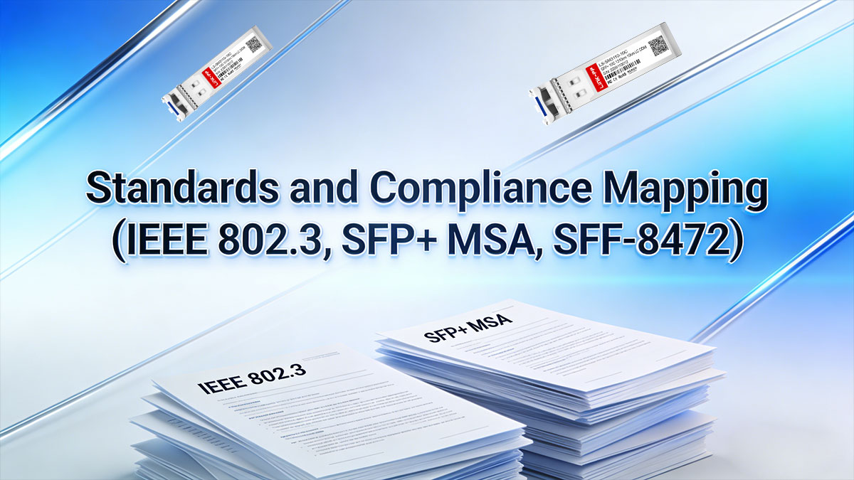
IEEE 802.3: Optical and Link-Level Definition
At the physical-layer level, IEEE 802.3 Clause 52 defines the 10GBASE-LR standard. This specification governs:
-
Line rate and encoding (10.3125 Gbit/s)
-
Optical wavelength band (around 1310 nm)
-
Transmitter and receiver optical limits
-
Link budget assumptions for a 10 km SMF channel
-
BER performance targets under defined stress conditions
IEEE compliance ensures that a module can meet the electrical-to-optical signaling requirements necessary for a standards-compliant 10G Ethernet link. However, IEEE 802.3 does not define the module’s mechanical form factor or management interface.
SFP+ MSA: Mechanical, Electrical, and Host Interface Compliance
The SFP+ MSA Multi-Source Agreement fills this gap by defining how the transceiver physically and electrically interfaces with the host system.
Key aspects governed by the SFP+ MSA include:
-
Module dimensions and cage interface
-
Electrical pin assignments and signaling levels
-
Hot-pluggability behavior
-
Power supply requirements and limits
-
High-speed electrical eye and jitter constraints
Compliance with the SFP+ MSA ensures that a 10Gbe LR module can be safely inserted into any SFP+ port that follows the same agreement, regardless of vendor.
Importantly, the MSA does not mandate optical reach. A module may be mechanically compliant but still fail optical performance if it does not also meet IEEE 802.3 LR requirements.
SFF-8472: Digital Diagnostics and Monitoring
Operational visibility is defined separately by SFF-8472, which specifies Digital Optical Monitoring (DOM/DDM).
This standard defines:
-
Which parameters must be monitored (Tx/Rx power, temperature, voltage, bias current)
-
How values are encoded and accessed via the I²C interface
-
Alarm and warning threshold behavior
-
Calibration methods and reporting accuracy classes
While DOM is not strictly required for link operation, it has become an industry expectation for SFP-10G-LR modules deployed in production networks.
How These Standards Work Together
In practice, a fully compliant SFP-10G-LR module must satisfy all three layers:
| Layer |
Standard |
What It Controls |
| Optical & Link |
IEEE 802.3 (Clause 52) |
Reach, wavelength, power, BER |
| Mechanical & Electrical |
SFP+ MSA |
Form factor, pinout, host signaling |
| Monitoring & Management |
SFF-8472 |
DOM/DDM telemetry and alarms |
Failure to comply with any one of these standards can lead to interoperability issues, unstable links, or reduced observability—even if the module is marketed as “10G LR.”
Common Compliance Pitfalls
-
“IEEE compliant” does not guarantee DOM support
IEEE 802.3 does not cover diagnostics.
-
MSA compliance does not imply optical performance
Mechanical fit alone does not ensure 10 km reach.
-
Vendor-specific EEPROM coding can override standards behavior
Some vendors intentionally restrict interoperability despite standards compliance.
Understanding this standards stack allows engineers to:
-
Evaluate datasheets beyond marketing labels
-
Identify the root cause of compatibility issues
-
Avoid false assumptions when mixing vendors
-
Design links that behave predictably across platforms
For procurement teams, standards awareness reduces vendor lock-in risk and improves long-term network resilience.
⏩ Interoperability and Vendor Coding (EEPROM, Compatibility, Lock-in Risks)
In theory, SFP-10G-LR is a standardized optical transceiver. In practice, interoperability is often influenced by EEPROM coding, vendor enforcement policies, and host platform behavior. Understanding these factors is essential when deploying multi-vendor 10G networks.
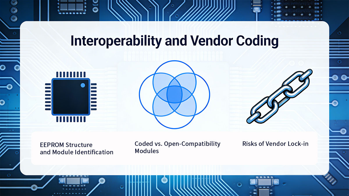
1. EEPROM Structure and Module Identification
Every SFP-10G-LR module contains an onboard EEPROM that stores identification and capability data defined by the SFP+ MSA and SFF standards. This data typically includes:
-
Vendor name and part number
-
Supported Ethernet standards (e.g., 10GBASE-LR)
-
Wavelength and reach identifiers
-
DOM/DDM capability flags
-
Manufacturing and serial information
Host systems read this information during module insertion to determine whether the transceiver is accepted, limited, or rejected.
2. Vendor Compatibility Enforcement Mechanisms
Some switch and router vendors implement software-level compatibility checks that go beyond MSA requirements. Common enforcement methods include:
-
Whitelisting specific vendor IDs
-
Blocking unknown or third-party EEPROM identifiers
-
Limiting features such as DOM or link speed
-
Generating warning messages or disabling ports
These mechanisms are policy decisions, not technical necessities. An optically and electrically compliant 10G SFP+LR module may still be rejected purely due to vendor coding.
3. Coded vs. Open-Compatibility Modules
From an interoperability perspective, 10G SFP+LR modules generally fall into two categories:
-
Vendor-coded modules
Programmed to match the EEPROM profile of a specific OEM platform.
-
Open-compatibility (multi-vendor) modules
Designed to work across a wide range of platforms without restrictive coding.
Both approaches can be technically compliant with IEEE and MSA standards. The difference lies in how host systems interpret and enforce EEPROM data.
4. Risks of Vendor Lock-in
Strict vendor coding introduces several long-term risks:
-
Higher replacement and expansion costs
-
Limited sourcing options during supply shortages
-
Delayed deployments due to platform-specific inventory
-
Reduced flexibility in network upgrades or migrations
For large-scale or long-lifecycle networks, these risks often outweigh the perceived benefits of single-vendor control.
5. Best Practices for Multi-Vendor Deployments
To minimize interoperability issues when using SFP-10G-LR:
-
Verify module acceptance on target platforms before volume deployment
-
Test DOM visibility and alarm behavior, not just link-up status
-
Avoid assuming compatibility based solely on “10G LR” labeling
-
Maintain documentation of validated firmware and platform versions
Where vendor enforcement is unavoidable, pre-coded modules or platform-specific profiles can be used without compromising optical performance.
Interoperability is not determined by optics alone. EEPROM coding and host policy often dictate whether an 10G LR module functions as intended. Understanding these non-optical constraints enables more resilient designs and prevents unnecessary vendor lock-in.
⏩ Common Specification Pitfalls and Deployment Mistakes
Despite the maturity of SFP-10G-LR, deployment issues are still common. Most failures do not stem from defective hardware, but from misinterpreting specifications or making incorrect assumptions about standards compliance. The following pitfalls appear repeatedly in real-world 10G deployments.
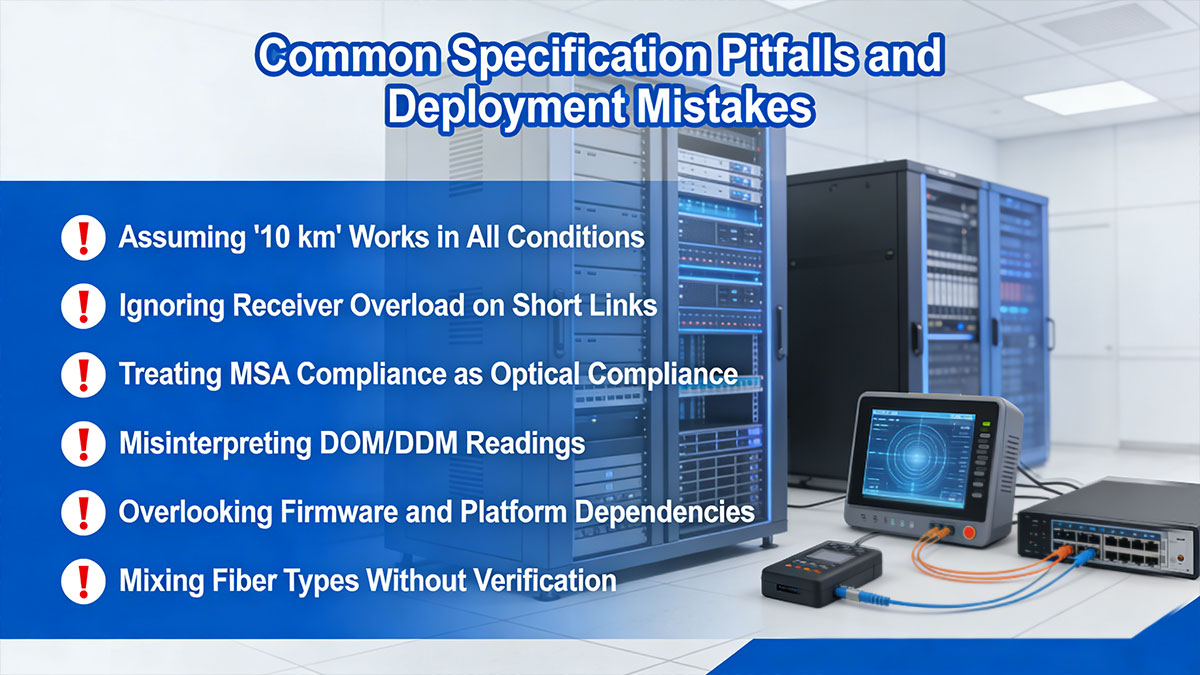
❗ Assuming “10 km” Works in All Conditions
The 10 km reach of SFP-10G-LR is based on a defined link model, not a universal guarantee. Engineers often overlook:
-
Higher-than-expected fiber attenuation
-
Excessive connector or patch-panel loss
-
Insufficient system margin for aging and temperature
A link that works at 8 km during commissioning may fail later if margin is not properly calculated.
Best practice: Always validate the optical power budget instead of relying solely on nominal reach.
❗ Ignoring Receiver Overload on Short Links
On short SMF runs (e.g., intra-building or campus links under 1 km), transmit power may exceed the receiver’s overload threshold.
Common symptoms include:
Best practice: Use optical attenuators when necessary, even on “long-reach” modules.
❗ Treating MSA Compliance as Optical Compliance
Mechanical compatibility does not imply optical correctness. A module may:
This misconception often leads to unstable or marginal links that pass basic checks but fail under stress.
Best practice: Verify IEEE 802.3 Clause 52 compliance in addition to SFP+ MSA claims.
❗ Misinterpreting DOM/DDM Readings
DOM data is frequently misunderstood or over-trusted. Common mistakes include:
-
Comparing absolute power values across different vendors
-
Treating DOM values as calibrated test measurements
-
Ignoring trends while focusing on snapshot readings
DOM is designed for monitoring and trend analysis, not precision acceptance testing.
Best practice: Use DOM to detect changes over time, not to replace optical test equipment.
❗ Overlooking Firmware and Platform Dependencies
Compatibility is not static. Platform firmware updates may:
-
Tighten EEPROM validation rules
-
Change alarm threshold handling
-
Affect DOM visibility or reporting
A module that worked previously may behave differently after an upgrade.
Best practice: Revalidate transceivers after major firmware or OS changes.
❗ Mixing Fiber Types Without Verification
While SFP-10G-LR is optimized for G.652 SMF, real networks often include:
These factors can introduce unexpected loss or dispersion penalties.
Best practice: Validate fiber plant characteristics rather than assuming standards compliance.
Key Takeaway
Most SFP-10G-LR deployment problems are preventable. Accurate interpretation of specifications—optical, electrical, and operational—is more important than the transceiver model itself. Engineers who treat specifications as design inputs rather than marketing labels achieve more stable and predictable networks.
⏩ Final SFP-10G-LR Recommendations and Engineering Checklist
SFP-10G-LR remains one of the most widely deployed 10G optical transceivers because its specifications are well-defined, mature, and predictable. When selected and deployed correctly, it delivers stable 10 km single-mode links with minimal operational complexity.
The key to success is not the “LR” label itself, but how well the module’s specifications align with the real network environment.
Engineering Recommendations
Before deployment, engineers should ensure that:
-
The optical power budget comfortably exceeds expected link losses
-
Fiber type, attenuation, and connector quality are verified
-
Receiver overload risks are evaluated on short SMF links
-
Module operating temperature aligns with the platform environment
-
DOM/DDM telemetry is available and readable on the host system
These checks reduce commissioning risk and prevent marginal links that fail under stress or aging.
SFP-10G-LR Deployment Checklist
Use the following checklist to validate 10G SFP LR Module deployments:
Optical
-
☐ IEEE 802.3 Clause 52 compliance confirmed
-
☐ Tx/Rx power ranges match link budget calculations
-
☐ Fiber plant verified (G.652 SMF, loss within limits)
Electrical & Mechanical
-
☐ SFP+ MSA compliance verified
-
☐ Power consumption within platform limits
-
☐ Thermal operating range suitable for the deployment environment
Management & Monitoring
-
☐ SFF-8472 DOM/DDM supported
-
☐ Alarms and thresholds visible on host
-
☐ Baseline readings recorded for future comparison
Interoperability
-
☐ Platform firmware compatibility validated
-
☐ EEPROM coding verified for target hardware
-
☐ Multi-vendor testing completed if applicable
When to Reconsider SFP-10G-LR
10G-LR may not be the optimal choice if:
-
Only multimode fiber is available (consider 10GBASE-SR)
-
Link distances exceed 10 km without amplification (consider ER or ZR)
-
Ultra-low power or ultra-high port density is the primary constraint
Specification-driven selection always leads to more resilient designs than defaulting to familiar part numbers.
If you are planning, upgrading, or validating a 10G single-mode link, treat SFP-10G-LR specifications as engineering inputs—not assumptions.
? Request engineering validation, compatibility testing, or sample evaluation from the LINK-PP Official Store to ensure your SFP-10G-LR deployment meets optical, electrical, and interoperability requirements from day one.
LINK-PP provides standards-compliant SFP+ 10G-LR modules with documented specifications, multi-vendor compatibility options, and technical support aligned with real-world deployment scenarios.


