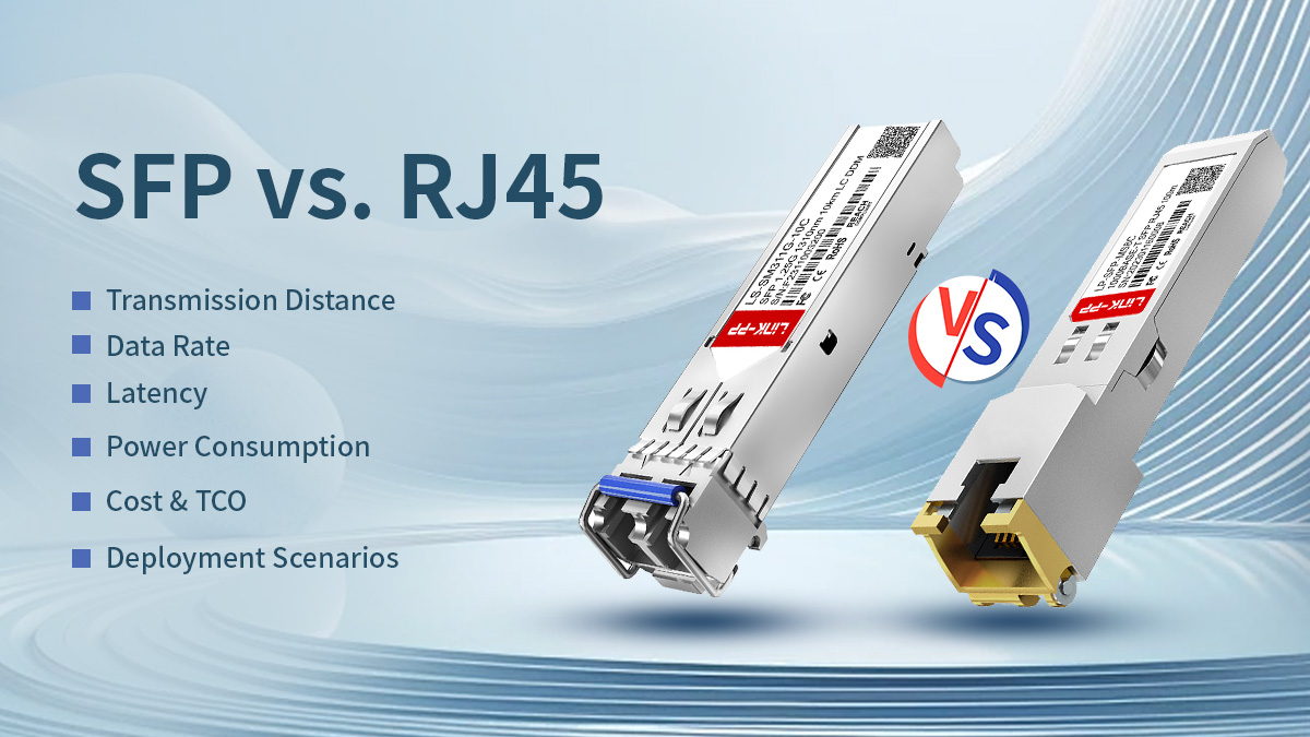
In modern Ethernet design the choice between SFP (Small Form-factor Pluggable) and RJ45 (8P8C copper) is rarely academic — it directly shapes cost, operability, power and long-term upgradeability. This guide helps engineers and technical decision-makers cut through marketing claims and vendor blur to make practical, verifiable choices for access layers, uplinks, data centers and industrial links.
You’ll get a concise, evidence-focused comparison (not opinionated marketing): what each interface is, how each performs across speed, reach, latency and power, and the operational trade-offs that determine total cost of ownership. Where useful, we call out standards and datasheet-level constraints (for example, copper Ethernet practical limits vs. optical SFP ranges), explain the root technical reasons behind differences (PHY/DSP overhead, optical budget, thermal impact), and provide an actionable decision checklist you can use in procurement and network design reviews.
This article is written for practising engineers and architects who want:
-
quick, defensible answers to “Which port today, which platform tomorrow?”
-
measured guidance for capacity planning, power/thermal budgeting and spare-part strategy
-
real-world deployment patterns (office access, top-of-rack, campus links, and harsh-environment use cases)
Read on for a structured, verifiable comparison that balances brevity with the technical depth you need to specify ports, select transceivers and justify choices to procurement and operations.
RJ45 and SFP serve different roles in Ethernet networks.
RJ45 ports (10/100/1000 and 10GBASE-T) are best suited for short-reach copper links up to 100 meters, offering low upfront cost and native Power over Ethernet (PoE) support. However, at higher speeds such as 10GBASE-T, RJ45 ports typically consume more power and introduce higher latency due to complex copper PHY processing.
SFP ports, using optical or copper transceivers, provide modular, scalable connectivity with longer reach, lower latency, and better suitability for uplinks, data centers, and backbone networks.
As a rule of thumb: choose RJ45 for short access links and PoE, and choose SFP for long distance, high speed, or future scalability.
✅ What Are SFP and RJ45 Interfaces?
Before comparing performance, cost, or deployment trade-offs, it is essential to understand what RJ45 and SFP actually represent — because they are often misunderstood as interchangeable “port types,” when in reality they serve very different architectural roles in Ethernet networks.
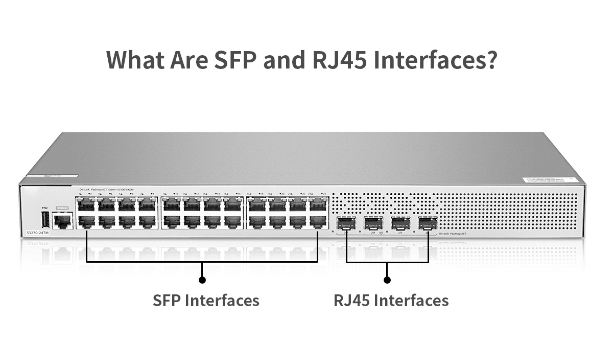
RJ45 Ethernet Interface (Copper-Based Connectivity)
RJ45 refers to the standardized 8P8C physical connector used for twisted-pair copper Ethernet. It is the dominant interface for 10/100/1000BASE-T and 10GBASE-T links over structured cabling such as Cat5e, Cat6, and Cat6a.
In typical deployments, the Ethernet PHY is integrated directly on the switch or NIC, and the RJ45 port is electrically fixed to copper transmission. Maximum supported link length is generally 100 meters, defined by IEEE Ethernet standards, beyond which signal attenuation, crosstalk, and noise become limiting factors.
RJ45 interfaces are widely adopted due to:
-
Low per-port hardware cost at 1G speeds
-
Direct compatibility with existing copper infrastructure
-
Native support for Power over Ethernet (PoE)
However, higher-speed copper standards such as 10GBASE-T require more complex PHY processing, leading to increased power consumption, heat generation, and latency compared to fiber-based alternatives.
SFP Interface (Pluggable Transceiver Architecture)
SFP (Small Form-factor Pluggable) is not a connector but a modular transceiver form factor. An SFP port consists of a standardized cage and electrical interface on the host device, into which different transceiver modules can be inserted.
Depending on the module used, an SFP port can support:
-
Optical fiber (via LC connectors, multimode or single-mode)
-
Direct-attach copper (DAC)
-
RJ45 copper Ethernet using copper SFP modules
This architecture decouples the switch hardware from the physical transmission medium, allowing the same port to support different link types, distances, and speeds. Variants such as SFP (1G), SFP+ (10G), and SFP28 (25G) share similar mechanical dimensions but differ electrically and in supported data rates.
The modular nature of SFPs is the foundation of their flexibility and long-term scalability.
Physical Form Factor vs. Logical Interface
A key distinction is that RJ45 defines a fixed physical and electrical interface, while SFP defines a pluggable interface framework.
In practice:
This difference explains why SFP-based platforms are commonly used for uplinks, backbone links, and data center switching, where requirements may evolve over time.
Supported Media Types and Connector Standards
RJ45 interfaces are limited to twisted-pair copper cabling, whereas SFP modules can support:
Connector types also differ: RJ45 ports terminate directly on copper jacks, while optical SFPs typically use LC duplex connectors.
Port Compatibility and Host Behavior
While an SFP port can accept different module types, host compatibility is not universal. Supported data rates, power limits, and firmware restrictions vary by vendor and platform. Engineers must verify:
-
Supported SFP/SFP+/SFP28 classes
-
Maximum module power draw
-
Approved or compatible transceiver lists
Understanding these constraints early prevents link failures, thermal issues, and interoperability problems during deployment.
✅ SFP vs. RJ45 Quick Metric Comparison
| Dimension |
RJ45 (copper) |
SFP (optical / modular) |
Practical recommendation |
| Typical max distance (Ethernet) |
~100m (copper, Cat5e/6/6A) |
meters → 100+ km (depends on SMF/optic) |
RJ45 for access; SFP for uplinks/long links. |
| Common data rates |
1G native, 10G (10GBASE-T up to 100m with Cat6A) |
1G, 10G, 25G, 40G, 100G (module dependent) |
Use SFP/SFP+/SFP28 for high density & higher line rates. |
| Latency |
Higher for DSP-heavy copper PHYs (esp. 10GBASE-T) |
Typically lower for direct-optical links (less PHY DSP) |
SFP favored for latency-sensitive apps. |
| Power (per-port) |
Lower at 1G; higher for 10GBASE-T due to DSP/PHY |
Varies by module; many 1G optics ≈ ~1 W; 10G/25G typically from ~1–3 W depending on module. |
|
| Cost (CAPEX) |
Lower per port (esp. for ≤1G) |
Higher module cost; saves on chassis replacement long term |
RJ45 cheaper short term; SFP better TCO for scale/futureproof |
| Flexibility |
Fixed medium (copper) |
Hot-swap media & speeds (optical or copper SFP) |
SFP wins on flexibility & inventory consolidation |
1. Transmission Medium & Distance
-
RJ45/copper: Standard Ethernet over twisted pair is generally limited to ~100 meters for typical categories (Cat5e/6/6A). For 10GBASE-T, Cat6A is spec'd for 100 m. Use Cat6 for shorter 10G runs (~55 m practical).
-
SFP (optical): With appropriate optics, SFPs support distances from a few meters (SR multimode optics) up to tens of kilometers and beyond (single-mode DWDM/ZX optics), and some transceivers support ~100 km+ with amplifiers or long-reach optics. This makes optical SFPs the clear choice for backbone and long-haul links.
2. Data Rate & Module Examples
-
1G SFP examples: Cisco MGBSX1 (850 nm MMF, 1G) — typical module power ≈ ~1 W (example datasheet).
-
10G SFP+ examples: 10GBASE-SR, 10GBASE-LR (multimode vs single-mode).
-
25G SFP28 examples: SFP28 modules for 25G with low-power variants; vendor datasheets show SFP28 designed for high density and energy efficiency.
Note: mechanical fit (same cage) ≠ electrical compatibility — check host vendor support before inserting higher-speed modules.
3. Latency
-
Why RJ45 can be higher latency: Modern high-speed copper PHYs (10GBASE-T) rely on complex signal processing and DSP (equalization, FEC, echo-cancellation) which introduces processing delay and additional power/heat. Optical transceivers often present a simpler PHY path, resulting in lower link latency in many setups. For latency-sensitive applications (HPC, finance), optical SFP links are preferable.
4. Power Consumption
-
Optical 1G SFP: many vendor datasheets show ≈0.7–1.2 W typical per module (example: SFP-10G-LR ~1 W).
-
10G SFP+ / 25G SFP28: power increases with speed and optics class. Vendor materials and datasheets for 25G SFP28 advertise low-power variants, but typical active optics often run from ~1.5 W up to ~3 W depending on reach and vendor. Use datasheet numbers when planning thermal and power budget.
-
10GBASE-T (RJ45 copper): 10GBASE-T PHYs historically consume more power (often several watts per port) vs equivalent SR optics because of the heavy PHY processing; this affects switch thermal design and OPEX.
Design implication: when planning a high-density switch population, multiply the per-port power of expected modules/ports to verify power supply and cooling capacity.
5. Cost & TCO Considerations
-
Upfront: RJ45 ports and copper cabling are usually lower capital cost for short-reach installations.
-
Operational / long-term: Optical SFPs reduce chassis replacements, allow gradual upgrades (swap transceivers, not chassis), and can reduce OPEX via lower per-port power (depending on PHY choice). For networks anticipating scaling to 10/25/50G, SFP ecosystems often yield a lower TCO over time. (Compare vendor pricing and lifecycle assumptions for accurate ROI.)
6. Deployment Scenarios
-
Office access (PoE endpoints, under 100 m): RJ45 (Cat6/Cat6A) — supports PoE and is cheapest for desk-side.
-
Top-of-Rack (ToR) to Leaf/Spine uplinks in data centers: SFP+ / SFP28 / QSFP (optical or DAC/AOC) for low latency and higher bandwidth.
-
Campus building-to-building links: SFP optical (single-mode) for kilometers.
-
Industrial / noisy EMI environments: Optical SFP preferred for immunity to EMI.
-
Mixed legacy environments: Consider copper SFP (RJ45 SFP) modules to keep modularity while using existing cabling — but validate power/thermal.
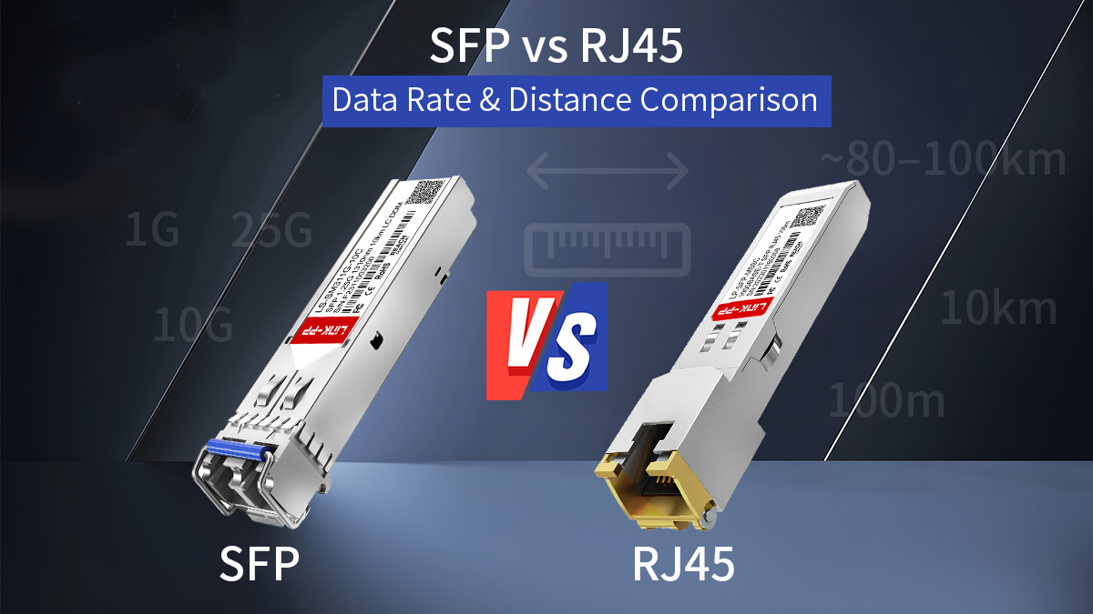
✅ SFP vs. RJ45: Data Rate & Distance Comparison
Below is a concise, engineer-focused comparison of the data-rate and distance characteristics you must verify from datasheets and cabling standards when you design or spec a network. I give typical, vendor-verified ranges and the practical caveats you must check before procurement.
Data Rates Supported by RJ45 Ethernet
RJ45 is the mechanical connector used for twisted-pair copper Ethernet. The common data rates you will encounter on RJ45 ports are:
-
10/100/1000BASE-T (1 Gbit/s): native and ubiquitous over Cat5e/Cat6 cabling.
-
2.5G/5G (Multi-Gig): supported over Cat5e/Cat6 in many deployments (IEEE 802.3bz).
-
10GBASE-T: supported over Cat6A to 100 m (Cat6 may be limited to ~55 m for 10G in some conditions).
These data rates are tied to the cable class and the electrical PHY in the device. Importantly, RJ45-based 10G (10GBASE-T) is a copper PHY standard that differs from the SFP+ electrical interface — the PHY does more signal processing (equalization, echo cancellation, FEC options), which affects power and latency (see later sections). For cabling compliance, follow TIA/EIA and ISO/IEC / IEEE wiring recommendations and test to permanent link/channel standards before certifying links.
Data Rates Supported by SFP, SFP+ and SFP28
SFP is a modular transceiver ecosystem whose supported line rates depend on the module and host port capability:
-
SFP (1G): 1000BASE-SX/LX (850 nm MMF / 1310 nm SMF) — standard 1 Gbit/s optics.
-
SFP+ (10G): 10GBASE-SR/LR/ER variants and DAC/AOC options (10 Gbit/s).
-
SFP28 (25G): 25GBASE-SR/LR and other 25G optics in the same small form factor but with different electrical requirements.
Vendors also ship dual-rate and multi-rate modules (e.g., 10/25G) and QSFP-to-SFP breakout solutions; check both the module and the host switch for supported baud/line rates. Cisco, Arista and other major vendors publish SFP/SFP+/SFP28 optical transceiver datasheet and validated part lists that specify supported speeds and any host FEC/RS-FEC requirements. Mechanical compatibility (same cage) does not guarantee electrical/firmware support — always verify the host acceptance matrix.
Maximum Transmission Distance (Copper vs. Fiber)
Copper (RJ45 / copper SFP modules / DACs):
-
Twisted-pair RJ45: standardized up to 100m for the usual Ethernet classes (1G, multi-gig, 10GBASE-T over Cat6A). Practical reach depends on cable quality, patching, and installation loss.
-
Direct Attach Copper (DAC): passive DACs typically used inside racks (up to ~7–10 m for passive); active copper or AOC variants extend that but are sold in fixed lengths.
Optical (SFP family):
-
Multimode fiber (MMF, e.g., OM3/OM4): short-reach optics (SR) commonly cover tens to hundreds of meters — typical 10G/25G SR modules are specified for 70–400 m depending on optics class and fiber grade; vendor module datasheets must be checked for the exact OM3/OM4 reach. For example, certain 25G SR modules list ~70–100 m on OM3/OM4 while extended short-reach (XSR/MR-XSR) variants support several hundred meters.
-
Single-mode fiber (SMF): LR modules commonly support ~10km, while long-reach/ZR/ZX optics can extend to tens to ~80–100km (often with dispersion/optical amplification as needed). Many 10G/25G LR modules are specified for 10 km on G.652 SMF.
Practical rule: if your link is ≤100m and PoE or desk connectivity is the priority, copper (RJ45) is usually appropriate; beyond that, optical SFPs or active/fiber solutions are the correct choice.
Practical Limits in Real Deployments
Real deployments add constraints beyond standards:
-
Cabling quality and installation: a nominal Cat6A link can still fail 10G at 100m if patch panels, connectors or installation practice add loss or crosstalk. Always test to channel/permanent link specs with a certifier.
-
Host & module compatibility: an SFP or SFP28 module must be approved by or tested with the host. Some platforms reject third-party optics at firmware level; test before bulk purchase.
-
Optical budget vs connector/splice loss: for fiber designs, calculate optical budget = Tx power − Rx sensitivity and include margins for connector loss, splices and aging. Vendor datasheets list transmitter power and receiver sensitivity to support this calculation.
-
Power and thermal density: at higher speeds (10GBASE-T or high-density SFP28), power per port and localized heat can create thermal limits that reduce usable port density unless chassis cooling and PSU capacity are sized appropriately. See vendor guidance when planning dense switch deployments.
| Interface / Module |
Data Rate |
Medium |
Typical Link Distance |
Notes |
| RJ45 (10/100/1000BASE-T / 2.5G/5G / 10GBASE-T) |
1G, 2.5G, 5G, 10G |
Copper (Cat5e/Cat6/Cat6A) |
Up to ~100 m |
Standard Ethernet copper reach |
| SFP+ 10GBASE-SR (MMF: OM3/OM4) |
10G |
Multimode Fiber |
~300–400 m |
300 m on OM3, 400 m on OM4 |
| SFP+ 10GBASE-LR (SMF: G.652) |
10G |
Single-Mode Fiber |
~10 km |
Standard SMF 10GBASE-LR |
| SFP+ 10GBASE-ER (SMF) |
10G |
Single-Mode Fiber |
~40 km+ |
Extended reach optics |
| SFP28 25GBASE-SR-S (MMF) |
25G |
Multimode Fiber |
~70–100 m |
70 m on OM3, 100 m on OM4 |
| SFP28 10/25GBASE-CSR-S (MMF) |
10/25G |
Multimode Fiber |
~300–400 m |
Using RS-FEC for full reach |
| SFP28 10/25GBASE-LR-S (SMF) |
10/25G |
Single-Mode Fiber |
~10 km |
Standard SMF reach |
| SFP28 25G-ER (SMF) |
25G |
Single-Mode Fiber |
~40 km |
Engineer-grade long reach |
Bottom line: SFP (optical) supports a much wider practical distance and flexible data-rate roadmap (1G → 10G → 25G and beyond) when matched to the correct module and fiber type. RJ45 (copper) is constrained by cable class and physical link budget (commonly 100 m) but remains the cost-effective choice for short access links and PoE endpoints. Always validate with vendor datasheets and on-site certification before finalizing a design.
✅ Latency Characteristics and Signal Integrity
Latency and signal integrity are often the deciding factors in high-performance designs. This section explains why different physical interfaces behave differently, what signal impairments matter at the physical layer, and how those effects translate into real-world latency, jitter and determinism.
PHY And DSP Processing Overhead
High-speed copper PHYs (for example, 2.5G/5G and especially 10GBASE-T) implement substantial digital signal processing (DSP) to cope with the noisy, bandwidth-limited copper channel. Typical PHY functions that add processing delay include:
-
Equalization and Echo Cancellation: Compensate for channel loss and crosstalk over twisted pair. These processes require filtering and adaptive algorithms that introduce pipeline latency.
-
Forward Error Correction (FEC): Some PHYs use FEC to improve bit-error performance at the cost of encoder/decoder latency and buffer needs.
-
SerDes / PCS Processing: Electrical interfaces translate between serialized bit streams and MAC frames; serialization/deserialization and clock recovery add small, but non-zero, latency.
-
Autonegotiation and Link Training: Initial link bring-up may add transient delay; some adaptive mechanisms can alter steady-state path behavior.
Optical transceivers (typical SFP/SFP+/SFP28 optics) generally present a simpler analog optical/electrical conversion and a less complex PHY pipeline at the device level. While optics still require SerDes and, in some cases, CDR (clock and data recovery), they often avoid the heavy DSP burden needed to equalize long copper channels. The practical result is that optical links commonly have lower per-link processing latency than equivalent copper PHYs, particularly when comparing 10GBASE-SR to 10GBASE-T.
Design implications / checklist
-
If microseconds matter, compare vendor-published PHY latency figures or measure on a lab bench.
-
Check whether FEC is enabled by default on the host — FEC reduces errors but increases latency.
-
For mixed environments, remember that a single copper link in an otherwise optical path can become the dominant latency contributor.
Electromagnetic Interference And Noise Sensitivity
Signal integrity on copper links is strongly influenced by electromagnetic interference (EMI) and channel impairments:
Practical guidance
-
For EMI-rich environments (industrial sites, substations), prefer optical SFP modules to minimize retrain events and jitter.
-
For high-density copper cabling, enforce certified Cat6A (or better) cabling and maintain separation from power/industrial runs.
Latency Impact In Low-Latency Networks
Some applications are extremely sensitive to one-way and deterministic latency (HFT, distributed storage replication, real-time control). Key practical points:
-
Relative Latency: Optical SR/LR links typically have lower processing latency than 10GBASE-T copper ports because of reduced PHY DSP. However, absolute latency is the sum of serialization delays, PHY processing, FEC, switch buffering, and queuing.
-
DAC vs Optical: Passive Direct Attach Copper (DAC) and short active DAC/AOC assemblies can offer very low link latency because they avoid optical/electrical conversion and long PHY DSP. For short, intra-rack links (a few meters), DAC often yields the lowest latency and jitter.
-
FEC and Buffering Tradeoffs: Enabling FEC improves BER and reach but introduces encoder/decoder latency. In networks where microseconds matter, plan FEC policy carefully — sometimes disabling or using low-latency FEC modes is warranted if link quality permits.
-
Switching Fabric & Queuing: Port choice matters, but so does the switch ASIC. Low-latency requirements demand switches that expose cut-through forwarding and minimal internal buffering; a low-latency port on a congested switch still suffers queuing delay.
Actionable recommendations
-
Use hardware timestamping (e.g., PTP hardware clocks) or dedicated packet timing testers to measure one-way latency under real load.
-
For ultra-low-latency use cases: prefer DAC (short) or optical SR with low-latency optics, ensure FEC policy is configured for latency targets, and select switches that support cut-through forwarding.
-
Include latency budgets in design documents: itemize serialization, PHY, FEC, and expected queuing delays so procurement and operations can validate targets.
Summary: copper RJ45 links (especially high-speed 10GBASE-T) incur additional DSP and PHY processing that increases latency and power; they are also more sensitive to EMI and crosstalk. Optical SFP solutions and short DAC assemblies generally provide lower and more deterministic latency. For latency-sensitive designs, the full signal chain — PHY, FEC, cabling, switch fabric and queuing — must be considered and measured, not assumed.
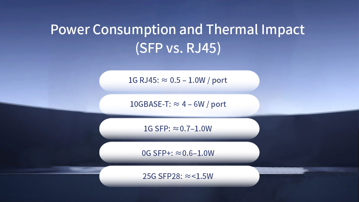
✅ Power Consumption and Thermal Impact (SFP vs. RJ45)
Power and thermal behavior are first-order design constraints for modern networks. Port-level power draw affects power-supply sizing, cooling, rack density, and operational cost (PUE). Below are the engineering facts you need to plan capacity and risk — with vendor-verified ranges and practical guidance.
Power Profile of RJ45 and 10GBASE-T Ports
10GBASE-T (RJ45 copper) PHYs consume substantially more power per port than typical optical transceivers. Modern 10GBASE-T implementations commonly draw roughly 2–5 W per port, depending on PHY generation, cable length and link conditions; earlier PHYs used even more. This higher per-port power stems from intensive DSP functions (equalization, echo cancellation, FEC) required to maintain signal integrity over copper at 10 Gbit/s.
Engineering implications:
-
When populating a 48-port switch with 10GBASE-T ports, multiply the per-port watts by port count to estimate PSU and PDU requirements (e.g., 48 × 3 W ≈ 144 W just for PHYs, before optics or fans).
-
Power increases with reach and poor cabling quality; longer or marginal copper links force PHYs into higher power modes to maintain margin.
-
10GBASE-T heat is localized at the port area; chassis thermal design must accommodate concentrated dissipation.
Power Characteristics of Optical and Copper SFPs
Optical SFP/SFP+ modules typically consume far less power per port than 10GBASE-T copper PHYs, though exact figures depend on module class and reach.
Vendor-documented examples and typical ranges:
-
1G SFP modules commonly draw ≈0.7–1.0 W (many Cisco 1G SFPs list ~1 W typical).
-
10G SFP+ (SR / LR) optical transceivers are often in the ~0.6–1.0 W range for SR/LR parts; some specific 10GBASE-T SFP+ copper modules can draw ~2.5 W or more (see vendor tables).
-
SFP28 (25G) modules are engineered to be energy efficient; many 25G SMF/MMF parts advertise typical power <1.5 W, with low-power variants below 1 W for short-reach classes.
-
DAC / AOC assemblies: passive DACs (short, passive twinax) have negligible active power on the link (no laser drive), and active optical cables draw some module power but are typically lower than 10GBASE-T PHYs. Broadcom/Broadline examples show SFP+ optics with typical dissipation around 0.6 W for some parts.
Engineering implications:
-
At high port density, SFP+ or SFP28 optics usually reduce aggregate power and cooling requirements versus equivalent 10GBASE-T populations.
-
Some copper SFP (RJ45 in SFP) implementations exceed SFP MSA power guidelines and can approach or exceed 2 W; verify the module power rating in the datasheet.
Cooling and Port Density Considerations
Port-level power density — not only total watts — determines localized hot spots and cooling strategy. Two installs with equal total watts can differ in cooling needs if one concentrates power at front-panel ports (10GBASE-T) whereas the other spreads lower-power SFP optics across blades.
Practical guidance:
-
Rack / chassis thermal modelling: use vendor-supplied thermal envelopes and perform Computational Fluid Dynamics (CFD) or worst-case thermal validation when planning high-density deployments. Include transceiver worst-case power at high ambient temperatures.
-
Port placement & airflow: dense RJ45 PHY heat at front ports can reduce allowable adjacent port density or require additional airflow guidance; optical modules dissipate heat at module slots and along fiber breakout areas.
-
Fan and PSU sizing: fans scale with chassis thermal load. If expected per-port power pushes chassis into a higher fan speed band, plan for increased acoustic output and higher OPEX.
-
Operational monitoring: instrument platform telemetry (module power, chassis inlet temp, fan rpm) and include alarms to prevent thermal throttling or automatic port shut-down.
Example rules-of-thumb:
-
For mixed populations, budget per-port power × 1.2 as a safety factor for PSUs and thermal headroom, then verify with vendor worst-case numbers.
-
For dense 25G SFP28 switches, confirm SFP28 worst-case (not only typical) power to avoid thermal surprises under extended high ambient conditions.
Short Summary
-
10GBASE-T (RJ45) ports typically consume significantly more power (2–5 W) per port than equivalent optical SFP/SFP+ transceivers; this drives higher cooling and OPEX.
-
Optical SFP / SFP+ / SFP28 modules commonly operate in the <1 W to ~1.5 W range depending on class and reach, offering lower per-port power and enabling higher effective port density when thermal design is considered.
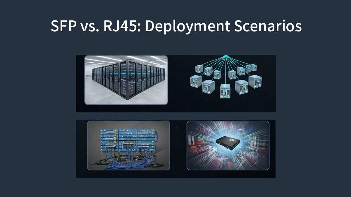
✅ Deployment Flexibility and Network Design
Choosing between RJ45 and SFP is ultimately a network design decision, not just a port-level preference. This section maps each interface to real deployment layers and explains why certain choices dominate in access, aggregation, data center, and industrial environments.
Access Layer and Edge Deployments
The access layer connects end devices such as PCs, IP phones, Wi-Fi access points, cameras, and IoT gateways. In this layer, RJ45 copper Ethernet remains the default choice.
Why RJ45 dominates at the edge:
-
Direct device compatibility: Most endpoint NICs expose RJ45 ports natively.
-
Power over Ethernet (PoE): RJ45 supports IEEE 802.3af/at/bt, enabling power and data over a single cable — essential for APs, VoIP phones, and surveillance.
-
Cost efficiency: Copper cabling and fixed RJ45 switch ports are inexpensive and easy to deploy for short runs (≤100 m).
-
Operational simplicity: Minimal optics inventory and simplified troubleshooting.
Where SFP may appear at the edge:
Aggregation and Uplink Scenarios
The aggregation layer concentrates traffic from multiple access switches and uplinks it toward the core. Here, SFP-based interfaces are typically preferred.
Reasons SFP excels for uplinks:
-
Distance flexibility: Optical SFPs easily exceed 100m, supporting building-to-building and campus links.
-
Higher sustained throughput: SFP+, SFP28 and beyond support 10G, 25G, and scalable upgrade paths.
-
Lower latency and power: Optical uplinks avoid the heavy DSP overhead of high-speed copper.
-
Media adaptability: The same switch model can support DAC (short), MMF (medium), or SMF (long) simply by changing modules.
RJ45 uplinks are generally limited to:
Data Center and High-Density Switching
In modern data centers, port density, power efficiency, and airflow drive interface selection. As a result, SFP-based designs dominate.
Common data center patterns:
-
Top-of-Rack (ToR):
-
Leaf-Spine fabrics:
-
High-density switching:
RJ45 usage in data centers is typically limited to:
-
Out-of-band management networks
-
Legacy server connections
-
Low-density, non-latency-critical segments
Industrial and High-EMI Environments
Industrial networks impose additional constraints: electrical noise, ground potential differences, vibration, and temperature extremes. These factors strongly influence interface choice.
Why SFP (fiber) is often preferred:
-
Immunity to electromagnetic interference (EMI): Optical fiber is non-conductive and unaffected by strong electrical fields.
-
Electrical isolation: Eliminates ground loops between buildings or machinery.
-
Extended reach: Single-mode fiber supports long runs without repeaters.
-
Reliability: Reduced error rates in electrically harsh environments.
RJ45 can still be used in industrial settings when:
However, even with shielding, copper links remain more susceptible to noise than fiber.
Matching Interface to Deployment Layer
-
Access / Edge: RJ45 for endpoints and PoE; SFP for uplinks
-
Aggregation: SFP for distance, throughput, and upgrade flexibility
-
Data Center: SFP/DAC/AOC for density, power efficiency, and low latency
-
Industrial: Fiber SFP for EMI immunity and electrical isolation
A well-designed network typically uses both RJ45 and SFP, assigning each interface where it provides the greatest engineering and economic advantage rather than forcing a single interface across all layers.
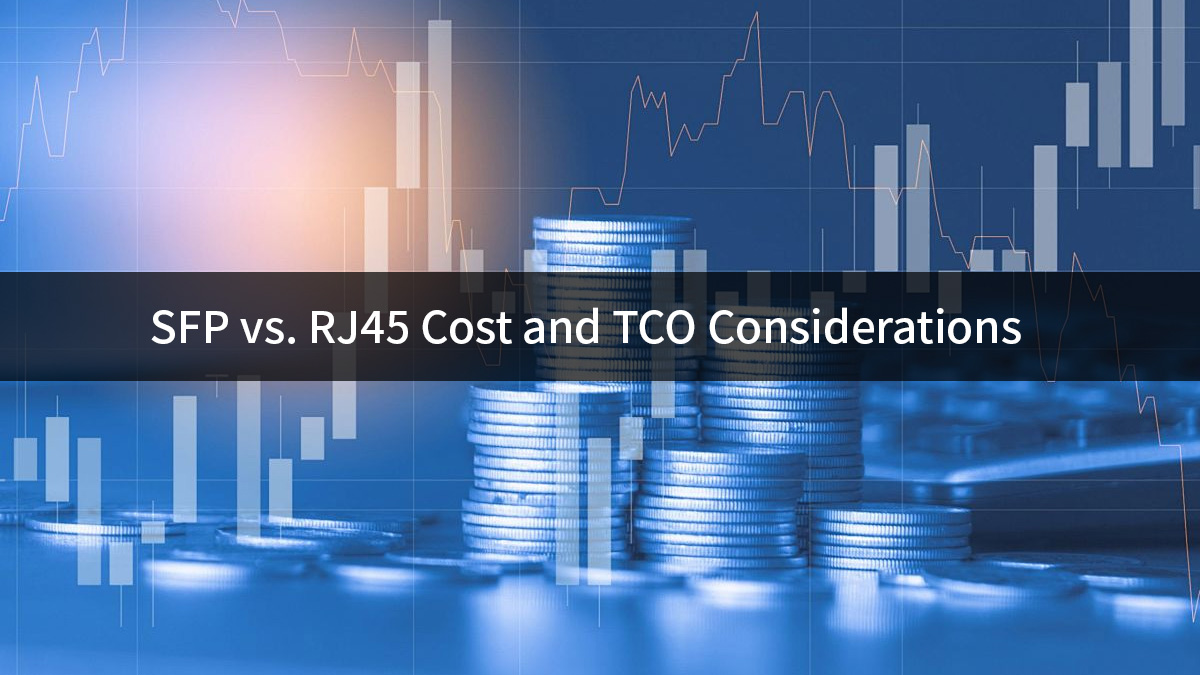
✅ SFP vs. RJ45 Cost and TCO Considerations
When comparing SFP and RJ45 interfaces, focusing only on port price or cable cost often leads to misleading conclusions. A proper Total Cost of Ownership (TCO) analysis must account for hardware, cabling, power consumption, cooling overhead, and long-term scalability. In medium-to-large networks, operational expenses frequently outweigh initial purchase costs over the system lifetime.
Initial Hardware and Cabling Costs
RJ45-based Ethernet typically offers a lower upfront entry cost at 1G and 2.5G speeds. Integrated copper PHYs eliminate the need for separate transceivers, and structured cabling (Cat5e/Cat6) is widely available and familiar to installers. For short access-layer links, this simplicity can reduce deployment time and initial capital expenditure.
SFP-based architectures introduce a modular cost model. Each port requires a transceiver, and fiber cabling (OM3/OM4 or single-mode) is generally more expensive than copper on a per-meter basis. However, this additional cost buys flexibility: the same switch port can be repurposed with different optics for reach, speed, or media type without replacing the switch hardware. In aggregation and backbone scenarios, this modularity often offsets higher initial costs by extending platform lifespan.
Power, Cooling, and Operational Costs
Power consumption is one of the most underestimated cost drivers in Ethernet design. Copper RJ45 ports—especially 10GBASE-T SFP—require complex PHY and DSP processing to compensate for attenuation, crosstalk, and echo over twisted-pair cabling. As a result, per-port power draw is significantly higher than that of optical SFP+ ports.
Because switches operate continuously, annual energy cost scales linearly with port power consumption. Higher power draw also translates into increased heat dissipation, raising cooling requirements and limiting achievable port density. In data centers and high-density wiring closets, these operational costs can surpass the original hardware investment within a few years.
Optical SFP and SFP+ modules generally consume less power per gigabit delivered, making them more cost-efficient over long service lifetimes. In environments with constrained cooling or strict energy budgets, lower per-port power can materially reduce overall TCO.
Scalability and Upgrade Path Economics
From a lifecycle perspective, SFP-based designs offer a clear economic advantage in scalability. Upgrading from 1G to 10G or 25G often requires only a transceiver change—fiber infrastructure and switch cages remain the same. This pay-as-you-grow model aligns well with evolving bandwidth demands and staged network expansion.
RJ45 deployments are more constrained by the physical limits of copper cabling. Moving beyond 1G may require higher-grade cables (Cat6a or better), reduced link lengths, or complete re-cabling. At higher speeds, such as 10GBASE-T, increased power and thermal costs further erode the apparent savings of copper.
| Cost Component |
RJ45 (1G / 10GBASE-T) |
SFP / SFP+ (Optical) |
Engineering Notes |
| Switch Port Hardware |
$25–$40 |
$15–$30 (SFP cage) |
SFP ports are often cheaper at the switch ASIC level; optics are modular |
| Transceiver / PHY |
Integrated (included) |
$20–$60 (1G/10G SR optics) |
RJ45 PHY is built-in; SFP cost depends on speed and reach |
| Cabling (per port) |
$5–$15 (Cat6/Cat6a) |
$10–$25 (OM3/OM4 fiber) |
Fiber costs more upfront but lasts longer across speed upgrades |
| Typical Power Draw |
1G: ~1 W
10GBASE-T: 4–6 W |
1G SFP: ~0.5 W
10G SFP+: ~1 W |
10GBASE-T requires DSP-heavy PHY processing |
| 5-Year Energy Cost* |
1G: ~$5
10G: ~$25–$38 |
1G: ~$2.5
10G: ~$5 |
Assumes $0.12/kWh, 24×7 operation |
| Cooling Overhead |
Medium to High |
Low |
Higher port power reduces achievable port density |
| Upgrade Cost (1G → 10G) |
New NICs
Possible re-cabling |
Replace optics only |
Fiber infrastructure remains reusable |
| Estimated 5-Year TCO |
1G: ~$40–$60
10G: ~$80–$120 |
1G: ~$45–$65
10G: ~$55–$75 |
Operational cost dominates at higher speeds |
Cost Formula
Annual Energy Cost per Port
$$ \text{Annual Cost} = \text{Power (W)} \times 24 \times 365 \times \text{Electricity Rate} $$
5-Year Energy Cost
$$ \text{5-Year Cost} = \text{Annual Cost} \times 5 $$
Example (10GBASE-T):
$$ 5 \times 24 \times 365 \times 0.12 \times 5 \approx \$26 $$
In practice:
RJ45 tends to minimize short-term costs in access networks, while SFP-based solutions deliver lower long-term TCO in aggregation, uplink, and data-center environments where power efficiency, density, and future upgrades matter most.
✅ How to Pick the Right Interface: SFP or RJ45
Choosing between SFP and RJ45 is not a theoretical debate. In real networks, the correct interface depends on link role, distance, power budget, and long-term scalability. Use the checklist below to make a defensible, engineering-driven decision.
-
Use RJ45 for short, cost-sensitive access links and PoE endpoints
-
Use SFP for long distance, low latency, high speed, or scalable network designs
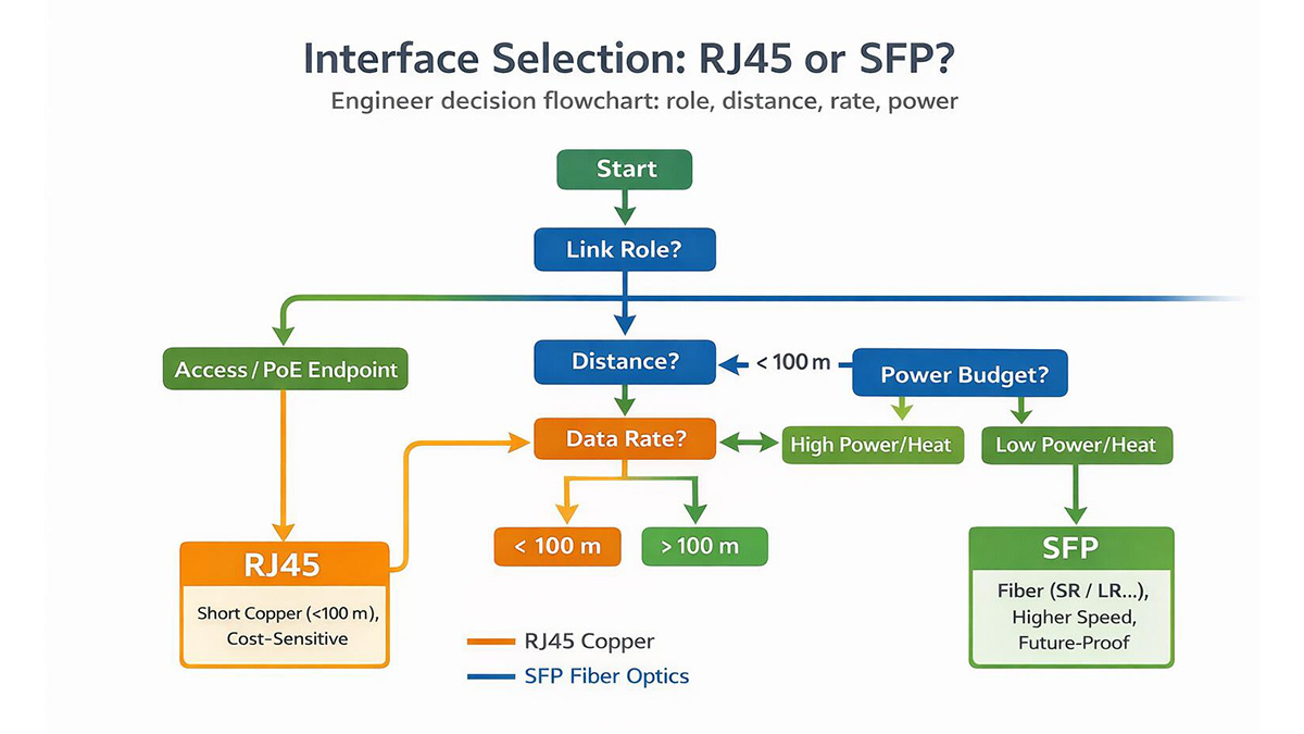
1. Define the Link Role
Start by identifying where the port sits in the network:
-
Access layer: endpoints, cameras, APs, PoE devices
-
Uplink: switch-to-switch aggregation
-
Backbone / inter-rack: long-haul, high-capacity paths
As a rule, RJ45 fits access links, while SFP is preferred for uplinks and backbone connections.
2. Distance Requirement
Determine the physical link length and medium constraints:
For fiber links, compute optical budget (Tx power − Rx sensitivity − link loss) and select the correct optic type. Do not rely on nominal distance alone.
3. Data Rate and Future Growth
Plan for bandwidth beyond today’s requirement:
-
RJ45 upgrades may require new NICs, switches, or re-cabling
-
SFP-based designs often scale by replacing transceivers only
If 10G today may become 25G or higher within 3–5 years, SFP cages provide a clearer upgrade path.
4. Host Compatibility
Mechanical fit does not guarantee acceptance.
This is especially critical for SFP/SFP+/SFP28 optics in branded switches.
5. Power and Thermal Budget
Account for total power consumption, not just per-port specs:
-
Sum module power × port count
-
Add base switch or chassis power
-
Consider cooling limits and port density
High-power interfaces (e.g., 10GBASE-T) can reduce usable port density in dense switches.
6. Inventory and Spares Strategy
Operational simplicity matters:
-
Fewer optic SKUs reduce inventory complexity
-
Modular SFP ports allow shared spares across platforms
-
Fixed RJ45 ports often require device-level spares
For large deployments, modularity lowers operational friction.
7. Cost Model (CAPEX + OPEX)
Avoid single-number comparisons.
At higher speeds, operational cost often outweighs initial hardware price.
8. Monitoring and Telemetry Needs
If link visibility is important:
RJ45 links typically offer far less granular physical-layer visibility.
✅ SFP vs. RJ45 — Frequently Asked Questions
Q1: Can Cat6A support 10Gbps up to 100 meters?
A: Yes. Cat6A is specified for 10GBASE-T up to 100 meters under TIA/EIA and ISO standards. Standard Cat6 cables can also carry 10Gbps, but in many real-world deployments the practical limit is ~55 meters, depending on cable quality, alien crosstalk, and installation conditions.
Q2: Is SFP always lower latency than RJ45?
A: In most cases, optical SFP links exhibit lower latency than 10GBASE-T RJ45 links. This is because high-speed copper Ethernet relies on DSP-heavy PHY processing (e.g., echo cancellation and FEC), which adds extra delay. The exact latency difference—typically measured in microseconds—depends on the PHY design and switch vendor implementation.
Q3: How much power does an SFP module consume?
A: Power consumption varies by speed and optic class:
Always refer to the SFP module datasheet when planning power and thermal budgets, especially in high-density switches.
Q4: Can I use copper SFP (RJ45 SFP) modules to avoid rewiring?
A: Yes. Copper SFP modules provide an RJ45 interface inside an SFP form factor, allowing reuse of existing copper cabling while keeping the switch port modular. However, verify:
-
Supported data rates (1G vs 10G)
-
Power and heat dissipation limits
-
Switch vendor compatibility and acceptance lists
Mechanical insertion alone does not guarantee operational compatibility.
Q5: Which interface is better for future upgrades?
A: SFP-based designs are generally more future-proof. Upgrading speeds often requires only swapping transceivers, while RJ45 upgrades may involve new PHYs, NICs, switches, or re-cabling—especially beyond 1G.
Q6: Is RJ45 still a good choice in modern networks?
A: Absolutely. RJ45 remains ideal for short access links, PoE devices, and cost-sensitive deployments. The key is using it where its strengths—simplicity and ubiquity—outweigh its distance, power, and scalability limitations.
Q7: When should SFP be the default choice?
A: SFP is typically preferred for uplinks, aggregation layers, data centers, long-distance runs, low-latency paths, and scalable network designs where power efficiency and upgrade flexibility matter.
✅ Conclusion
There is no universal “better” choice between SFP and RJ45. Each interface is optimized for different roles in an Ethernet network. The correct decision comes from aligning distance, bandwidth, power, and scalability requirements with the actual deployment scenario.
Final Verdict by Deployment Scenario
| Scenario |
Recommended Interface |
Engineering Rationale |
| Access Layer (PCs, APs, Cameras) |
RJ45 |
Low cost, simple deployment, native PoE support, ≤100 m copper runs |
| Switch-to-Switch Uplinks |
SFP / SFP+ |
Lower latency, lower power per port, longer reach, higher reliability |
| Data Center / Inter-Rack Links |
SFP+ / SFP28 |
High port density, scalable speeds (10G→25G), efficient cooling |
| Long-Distance Connections |
SFP (Fiber) |
Fiber supports hundreds of meters to tens of kilometers |
| High-Density Switching |
SFP-Based Design |
Lower power and thermal load than 10GBASE-T RJ45 |
| Industrial / High-EMI Environments |
SFP (Fiber) |
Immunity to electromagnetic interference and ground loops |
| Reuse Existing Copper Cabling |
RJ45 or Copper SFP |
Avoids rewiring; verify power, heat, and host compatibility |
-
RJ45 remains the most practical choice for short, cost-sensitive access links and PoE-powered devices.
-
SFP-based interfaces excel in uplinks, aggregation, data centers, and scalable architectures, where distance, latency, power efficiency, and future upgrades matter more than initial port cost.
From a long-term engineering perspective, SFP designs typically deliver lower operational cost and higher flexibility, especially at 10G and above.
For engineers and network designers evaluating SFP cages, SFP transceivers, and RJ45-to-SFP migration paths, explore technical datasheets and compatibility-focused components at the LINK-PP Official Store. LINK-PP solutions are designed for standards compliance, power efficiency, and real-world deployment reliability across enterprise, data center, and industrial networks.


