? Introduction
Optical transceivers are the fundamental building blocks of modern fiber-optic communication systems. They enable the conversion between electrical and optical signals, allowing high-speed data transmission across switches, routers, servers, and other network equipment. Among the various form factors available today, SFP (Small Form-factor Pluggable) optical transceivers remain one of the most widely deployed solutions due to their compact footprint, hot-swappable design, and broad support for Ethernet and fiber-optic standards.
In real-world engineering, deployment, and procurement scenarios, the Optical Transceiver Datasheet serves as the most authoritative technical reference. Unlike marketing summaries or compatibility lists, a datasheet defines the verified electrical, optical, mechanical, and environmental characteristics of a transceiver module. It is the primary document engineers rely on to assess link feasibility, confirm standard compliance, and ensure interoperability across network platforms.
This technical documentation explains how to read and interpret an optical transceiver datasheet, with a practical focus on commonly used SFP module datasheet covering both 1G (1000BASE-SX / 1000BASE-LX) and 10G (10GBASE-SR / 10GBASE-LR) optical transceivers. By referencing official datasheets from LINK-PP, this guide bridges the gap between specification tables and real-world network design decisions.
What You Will Learn from This SFP Datasheet Guide
This guide is designed to help network engineers, system integrators, and technical procurement professionals translate datasheet parameters into deployment-ready knowledge. By reading this document, you will learn how to:
-
Understand the role and structure of an optical transceiver datasheet
-
Identify critical specifications such as wavelength, transmission distance, optical power budget, and receiver sensitivity
-
Distinguish between multimode and single-mode SFP transceivers based on datasheet definitions
-
Compare 1G and 10G SFP module datasheets for different application requirements
-
Evaluate module suitability and compatibility for mainstream platforms from Cisco, Huawei, Juniper, and similar vendors
-
Access and reference official optical transceiver PDF for accurate engineering validation
By mastering these fundamentals, you will be able to select optical transceiver modules with greater confidence, reduce interoperability risks, and design fiber-optic links that align with both technical standards and operational requirements.
? What Is an Optical Transceiver Datasheet?
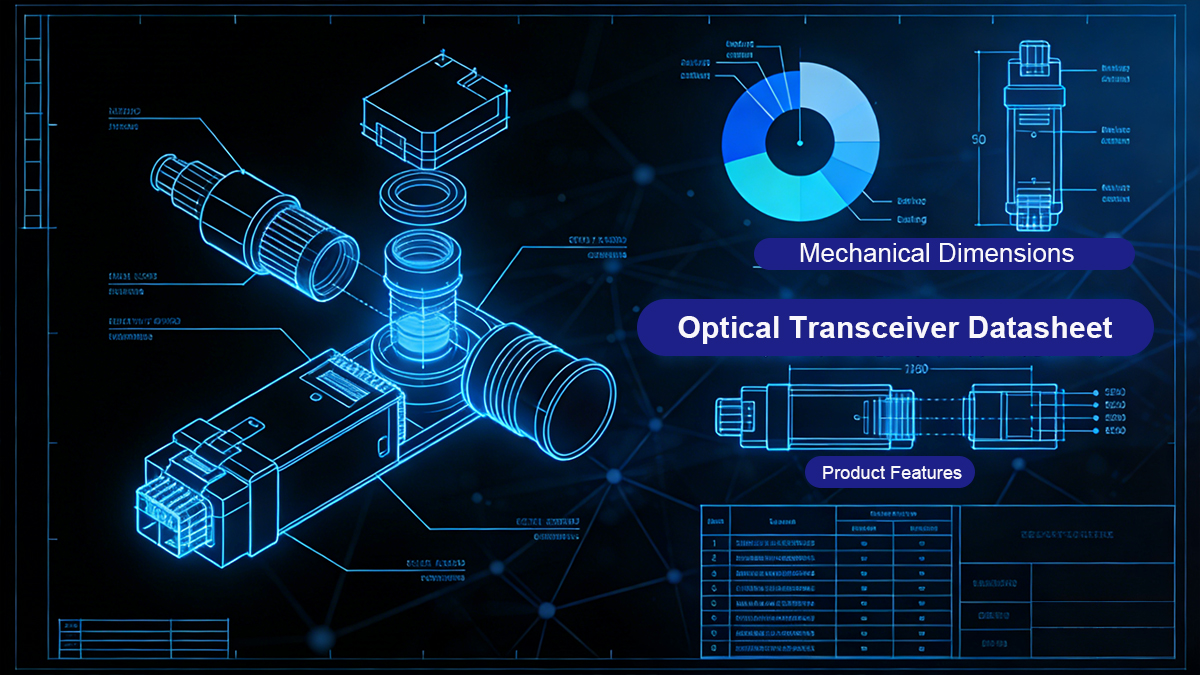
An Optical Transceiver Datasheet is an official technical document published by the manufacturer that defines the optical, electrical, mechanical, and environmental characteristics of a transceiver module. For network engineers and system integrators, it is the primary reference used to determine whether a module complies with applicable standards and meets the physical and performance requirements of a specific network link.
Unlike product summaries or compatibility tables, an optical transceiver datasheet provides specification-level data based on design validation and testing. Parameters such as operating wavelength, optical transmit power, receiver sensitivity, power consumption, and operating temperature range are essential for accurate link budget calculations, interoperability validation, and long-term network reliability.
In engineering, procurement, and deployment scenarios, optical transceiver datasheets are commonly used to:
-
Verify compliance with IEEE 802.3 and relevant MSA standards
-
Confirm supported wavelength, fiber type, and maximum transmission distance
-
Evaluate electrical characteristics, including supply voltage and power consumption
-
Assess environmental limits, such as commercial or industrial operating temperature ranges
-
Ensure compatibility with switches and routers from vendors such as Cisco, Juniper, and Huawei
By relying on datasheet specifications rather than assumptions, engineers can significantly reduce interoperability risks and avoid mismatched installations.
How to Read an Optical Transceiver Datasheet (Step by Step)
To interpret an optical transceiver datasheet accurately, a structured review process is recommended.
Step 1: Confirm the supported standard and data rate
Identify whether the module complies with standards such as 1000BASE-SX, 1000BASE-LX, 10GBASE-SR, or 10GBASE-LR, and verify the nominal data rate specified in the datasheet.
Step 2: Review key optical parameters
Examine the operating wavelength, transmit optical power, and receiver sensitivity values. These parameters determine whether the module can meet the required optical link budget for the intended fiber type and distance.
Step 3: Check transmission distance and fiber compatibility
Validate the maximum supported transmission distance over multimode fiber (MMF SFP) or single-mode fiber (SMF SFP) as explicitly stated in the datasheet.
Step 4: Evaluate electrical and power specifications
Review the specified supply voltage range and maximum power consumption, which are critical considerations in high-density switch and router deployments.
Step 5: Verify environmental and mechanical specifications
Ensure the operating temperature range, storage conditions, form factor, and connector type align with the deployment environment and host equipment requirements.
Following this step-by-step approach allows engineers and procurement teams to translate datasheet parameters into informed decisions, ensuring reliable, standards-compliant optical network deployments.
? Key SFP Module Specifications Decoded
Understanding the technical nomenclature in an SFP datasheet is vital for avoiding link failures. Below are the most important specification groups you will find in LINK-PP SFP/SFP+ datasheets, with practical notes on what each parameter means for design and procurement.
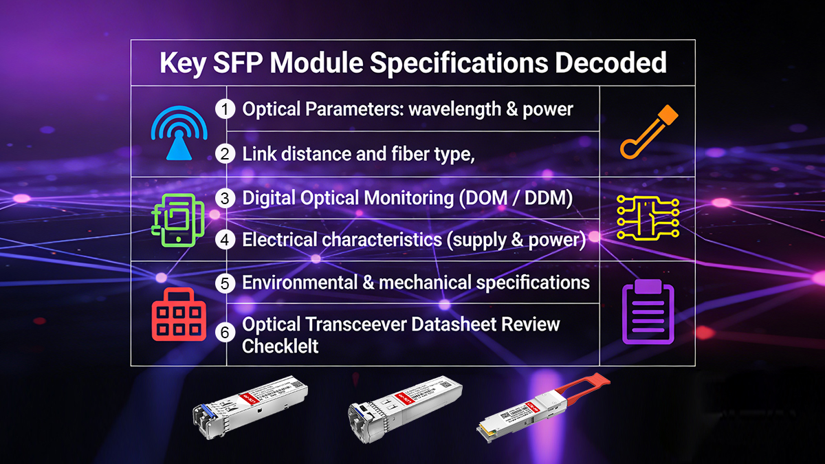
1. Optical Parameters: wavelength & power
The operating wavelength (nm) determines the fiber type and distance class:
-
850 nm — VCSELs for multimode fiber (MMF), used in short-reach modules (e.g., 10GBASE-SR / 1000BASE-SX). Example: LINK-PP 10G SR modules use a centre wavelength around 840–860 nm.
-
1310 nm / 1550 nm — lasers for single-mode fiber (SMF), used in long-reach modules (e.g., 10GBASE-LR / 1000BASE-LX / ZX).
Key power parameters in the optical section:
-
TX (transmit) average output power — usually listed as a min/typ/max range (e.g., −6.0 to −0.5 dBm for a 10G SR part). TX power, together with receiver sensitivity, defines the usable optical budget.
-
RX (receiver) sensitivity — the minimum optical power at the receiver input required to meet the specified BER (for example, −10.5 dBm for a 10G SR part, −18 dBm for a 1G SX part, −23 dBm for a 1G LX part). If the RX sensitivity is higher (less negative) than the expected received power, the link will fail.
Practical notes:
-
Always calculate link budget = TX minimum power − RX sensitivity and compare that to fiber attenuation over distance plus connector/splice loss.
-
If RX input is above the receiver overload value, use attenuation to avoid saturation and packet errors. Datasheets list receiver overload (e.g., 0.5 dBm for some 10G SR).
2. Link distance and fiber type
Datasheets specify maximum reach under defined fiber types and conditions:
-
1000BASE-SX (1G MMF) — typical LINK-PP SFP short-reach modules support up to 550 m on 50/125 µm MMF and ~300 m on 62.5/125 µm MMF, depending on fiber grade.
-
10GBASE-SR (10G MMF) — short-reach 10G SFP+ modules commonly support OM3/OM4 distances (LINK-PP example: up to 300 m for OM3 at 10.3 Gbps).
-
1000BASE-LX / 10GBASE-LR (SMF) — long-reach single-mode modules typically support up to 10 km over G.652 SMF (values in LINK-PP 1G/10G SMF datasheets).
-
1000BASE-ZX / other ZX variants — defined for ultra-long haul (dozens of kilometers; check each datasheet for exact reach and requirements).
Practical notes:
-
Datasheet reach assumes a specified fiber type and attenuation (e.g., 0.35 dB/km or 0.4 dB/km). Always match the module’s stated reach to the actual fiber type and planned margins.
-
For mixed-grade fiber links (older 62.5/125 µm vs newer 50/125 µm), consult the datasheet’s table—100/550 m differences are common for 1G MMF parts.
3. Digital Optical Monitoring (DOM / DDM)
Most modern SFP/SFP+ modules implement SFF-8472 Digital Diagnostic Monitoring (DDM / DOM) to report real-time operating metrics:
-
Typical monitored parameters: transmitted power, received power, laser bias current, supply voltage, and internal temperature. Datasheets specify the monitored ranges and recommended accuracy/calibration.
Practical notes:
-
DOM is essential for preventative maintenance and troubleshooting: you can trend RX/TX power and temperature to detect fiber degradation, connector problems, or impending module failure.
-
Check the datasheet for whether DOM is internally calibrated or supports external calibration, and for the stated measurement accuracy.
4. Electrical characteristics (supply & power)
The electrical section lists host interface and power details:
-
Supply voltage (typically 3.3 V with recommended operating range).
-
Power consumption / supply current (Icc) — important in high-density switch environments; check both typical and maximum values (e.g., 260–300 mA typical for some SFP/SFP+ parts).
-
Electrical interface compliance — SFP/SFP+ MSA signaling, differential input/output swings, and pin definitions. Datasheets provide timing diagrams and I/O levels.
Practical notes:
5. Environmental & mechanical specifications
Datasheets detail conditions that affect reliability:
-
Operating case temperature ranges — commercial (0 to +70 °C), extended, and industrial (e.g., −40 to +85 °C) variants are commonly offered. Choose the grade that matches the physical environment.
-
Storage temperature and humidity ranges.
-
Form factor and connector type — SFP / SFP+ footprint, duplex LC connector, hot-pluggable mechanical dimensions.
Practical notes:
-
For telecom, industrial, or outdoor sites, use modules rated for the appropriate temperature class to avoid early failures or performance degradation.
6. Optical Transceiver Datasheet Review Checklist
| Check Item |
Key Verification |
| Standard & Speed |
Match IEEE standard and data rate (e.g., 1.25 Gbps, 10.3 Gbps) |
| Link Budget |
TX (min) − RX sensitivity ≥ fiber + connector losses |
| Fiber & Distance |
Supported reach for OM2/OM3/OM4 or G.652 SMF |
| DOM / DDM |
Availability of optical power, temperature, voltage monitoring |
| Power & Temperature |
Power consumption and operating temperature within system limits |
By decoding these key sections of an SFP PDF you transform a table of numbers into practical deployment decisions — reducing deployment risk and ensuring the link performs predictably in real networks.
? Common Types of Optical Transceivers Datasheet
Optical transceiver datasheets vary by data rate, wavelength, and supported transmission distance. Among them, SFP-based optical transceivers remain the most widely deployed form factor for 1G and 10G Ethernet links. Below is a structured overview of common optical transceiver datasheets, highlighting how specifications differ across typical short-reach and long-reach applications.
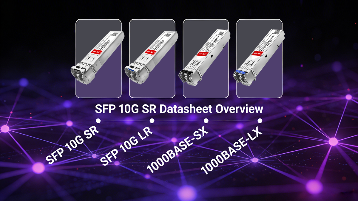
▶ SFP 10G SR Datasheet Overview
The SFP 10G SR datasheet describes a short-reach 10G optical transceiver operating at 850 nm over multimode fiber. This type of module is optimized for high-density, short-distance connections.
Typical datasheet specifications
| Parameter |
Value |
| Data rate |
10 Gbps |
| Wavelength |
850 nm |
| Fiber type |
OM3 / OM4 multimode fiber |
| Maximum distance |
Up to 300 m (OM3), up to 400 m (OM4) |
SFP 10G SR optical transceivers are commonly used for intra-data-center links, such as server-to-switch and switch-to-switch connections within the same facility.
▶ SFP 10G LR Datasheet Overview
The SFP 10G LR datasheet defines a long-reach 10G optical transceiver operating at 1310 nm over single-mode fiber. Compared to SR modules, LR transceivers support much longer transmission distances.
Typical datasheet specifications
| Parameter |
Value |
| Data rate |
10 Gbps |
| Wavelength |
1310 nm |
| Fiber type |
Single-mode fiber (SMF) |
| Maximum distance |
Up to 10 km |
SFP 10G LR modules are widely deployed in enterprise backbones, campus networks, and inter-building fiber links.
▶ 1000BASE-SX SFP Datasheet Overview
The 1000BASE-SX SFP datasheet covers 1G optical transceivers designed for short-distance transmission over multimode fiber at 850 nm.
Typical datasheet specifications
| Parameter |
Value |
| Data rate |
1 Gbps |
| Wavelength |
850 nm |
| Fiber type |
Multimode fiber (MMF) |
| Maximum distance |
Up to 550 m (OM2), longer on OM3/OM4 |
SFP 1G SX optical transceivers are commonly found in access-layer and legacy enterprise networks where 1G bandwidth remains adequate.
▶ 1000BASE-LX SFP Datasheet Overview
The 1000BASE-LX SFP datasheet specifies 1G long-reach optical transceivers operating at 1310 nm over single-mode fiber.
Typical datasheet specifications
| Parameter |
Value |
| Data rate |
1 Gbps |
| Wavelength |
1310 nm |
| Fiber type |
Single-mode fiber (SMF) |
| Maximum distance |
Up to 10 km |
SFP 1G LX optical transceivers are typically used for campus backbones and metropolitan access links, providing stable long-distance performance at Gigabit Ethernet speeds.
▶ SFP Datasheet PDF Downloads
To streamline your technical evaluation, we have compiled the official Optical Transceiver Datasheet PDF files for LINK-PP's most popular models. These documents cover electrical interfaces, pin definitions, and regulatory compliance.
By reviewing these optical transceiver datasheets side by side, engineers and procurement teams can quickly determine which module type aligns with their fiber infrastructure, distance requirements, and bandwidth targets.
? Application Scenarios of Optical Transceiver Modules
Optical transceiver modules defined in standard optical transceiver datasheets are deployed across a wide range of network environments. Each scenario places different requirements on transmission distance, bandwidth, reliability, and environmental tolerance.
● Data centers
In data center environments, optical transceivers are primarily used for high-density, short-reach connections between servers, top-of-rack switches, and aggregation layers. Short-reach modules such as SFP 10G SR and 1000BASE-SX are commonly selected due to their compatibility with multimode fiber, low latency, and cost efficiency.
● Enterprise switches and routers
Enterprise networks rely on optical transceivers for both access-layer and backbone connectivity. Long-reach modules such as SFP 10G LR and 1000BASE-LX are frequently used to interconnect wiring closets, buildings, or remote facilities over single-mode fiber while maintaining stable, standards-compliant performance.
● Industrial Ethernet networks
Industrial deployments often require optical transceivers with extended operating temperature ranges and enhanced reliability. In these environments, datasheet parameters related to temperature tolerance, power stability, and long-term availability are as critical as optical reach and data rate.
● Campus and metropolitan area networks
Campus and metro networks typically span longer distances and multiple fiber segments. SFP transceivers specified for long reach and higher optical budgets are essential to maintain signal integrity across distributed locations.
Because each application scenario imposes different technical constraints, careful review of the optical transceiver datasheet is necessary to select the appropriate combination of speed, distance, fiber type, and environmental rating for reliable network operation.
? Compatibility and Interoperability Considerations
Compatibility is a critical factor when selecting optical transceiver modules, especially in multi-vendor network environments. Although SFP optical transceivers are defined by industry standards, interoperability in real-world deployments depends on both standards compliance and vendor-specific implementation details.
Modern SFP optical transceivers are generally designed to operate with mainstream networking equipment. Most standards-compliant modules support interoperability with switches and routers from major vendors, including Cisco, Juniper, and Huawei. However, some OEM platforms implement additional validation mechanisms that go beyond the optical and electrical specifications defined in the datasheet.

EEPROM Coding and Compatibility Validation
Many network equipment vendors rely on EEPROM data within the SFP module to identify and authenticate third-party optics. As a result, compatibility testing typically includes:
-
EEPROM coding verification to match vendor-specific identification requirements
-
Link establishment and stability testing under normal operating conditions
-
Performance validation across temperature and voltage ranges
Failure to meet these requirements can result in warning messages, disabled ports, or unstable links—even if the optical parameters are otherwise compliant.
Multi-Vendor Interoperability
A common concern among network engineers and procurement professionals is whether a single optical transceiver module can operate reliably across different switch platforms. LINK-PP optical transceivers are engineered for broad interoperability and are validated against a wide range of mainstream vendors, including:
-
Cisco, Juniper, Arista
-
Huawei, H3C, ZTE
-
Dell, HPE, MikroTik
Through controlled EEPROM programming and systematic compatibility testing, LINK-PP modules are designed to integrate seamlessly into heterogeneous networks. This approach minimizes the impact of vendor lock-in while maintaining stable link performance and full standards compliance.
By carefully reviewing compatibility information in the optical transceiver datasheet and selecting modules with proven multi-vendor validation, organizations can reduce deployment risk and maintain flexibility across their network infrastructure.
? How to Choose the Right Optical Transceiver Module
Selecting the appropriate optical transceiver module requires more than matching a form factor. A careful review of the optical transceiver datasheet helps ensure long-term reliability, interoperability, and cost efficiency.
When evaluating different options, the following factors should be considered together rather than in isolation.
★ Required data rate
Start by confirming the required bandwidth for the application. Gigabit Ethernet (1G) transceivers are still widely used in access and legacy networks, while 10G transceivers are common in data centers and enterprise backbones. The datasheet should clearly state the supported standard and nominal data rate.
★ Transmission distance and fiber type
Match the module to the installed fiber infrastructure. Multimode fiber is typically used for short-reach links, while single-mode fiber is required for longer distances. Always verify that the maximum distance specified in the datasheet aligns with real-world link lengths and includes sufficient margin.
★ Operating temperature environment
Environmental conditions directly impact transceiver reliability. For controlled environments such as data centers, commercial-grade temperature ranges are usually sufficient. Industrial or outdoor deployments may require extended temperature-rated modules, which must be explicitly stated in the datasheet.
★ Equipment compatibility requirements
Confirm that the transceiver is compatible with the target switch or router platform. Datasheet information should be reviewed alongside vendor compatibility matrices, especially in environments with mixed equipment from different manufacturers.
★ Power consumption constraints
In high-density systems, power consumption and thermal output become critical. Reviewing maximum power consumption values in the datasheet helps prevent overheating and ensures compliance with the host equipment’s power budget.
| Selection Factor |
What to Check in the Datasheet |
| Data Rate |
Supported standard and speed (1G vs 10G) |
| Distance & Fiber |
Maximum reach and compatible fiber type (MMF or SMF) |
| Operating Temperature |
Commercial or industrial temperature range |
| Compatibility |
Verified operation with target switch or router platforms |
| Power Consumption |
Maximum power draw and thermal limits |
By comparing these parameters across multiple optical transceiver PDF datasheets, network engineers and procurement teams can make informed decisions that balance performance, compatibility, and total cost of ownership.
? Optical Transceiver Datasheet FAQ

Q1: What is the purpose of an optical transceiver?
An optical transceiver converts electrical signals from network equipment into optical signals for transmission over fiber, and converts received optical signals back into electrical form. It enables high-speed, long-distance data communication between switches, routers, and servers.
Q2: Is an optical transceiver the same as an optic module?
Yes. In networking contexts, “optical transceiver,” “optic module,” and “optical module” are commonly used interchangeably. All refer to a pluggable device, such as an SFP or SFP+, that provides optical transmission and reception functions.
Q3: What information should I check first in an optical transceiver datasheet?
The most critical items are the supported standard and data rate, operating wavelength, maximum transmission distance, fiber type, and compatibility with the target network equipment. These parameters determine whether the module can operate correctly in a given link.
Q4: Are third-party optical transceivers reliable?
High-quality third-party optical transceivers can be reliable when they are standards-compliant and properly tested for compatibility. Datasheets that clearly specify optical, electrical, and environmental parameters, along with documented interoperability testing, indicate a mature and dependable product.
Q5: Does every SFP module support DOM or DDM?
Not all modules support Digital Optical Monitoring. When supported, DOM/DDM capability is stated in the datasheet and allows real-time monitoring of parameters such as optical power, temperature, supply voltage, and laser bias current.
Q6: Why do different datasheets list different maximum distances for the same standard?
Maximum distance values depend on assumptions about fiber type, attenuation, connector loss, and optical budget. Datasheets specify standardized test conditions, so differences often reflect varying design margins or target applications rather than incompatibility.
These frequently asked questions address common concerns engineers and procurement teams encounter when reviewing optical transceiver datasheets and planning fiber-optic deployments.
? Conclusion
Understanding an optical transceiver datasheet is a foundational skill for network engineers and procurement professionals responsible for designing, deploying, and maintaining fiber-optic networks. By carefully reviewing key specifications—such as wavelength, transmission distance, optical budget, DOM support, and compatibility—you can confidently select SFP optical transceivers that deliver stable performance and long-term reliability.
A disciplined, datasheet-driven selection process reduces interoperability risks while improving scalability, cost control, and operational efficiency as network requirements evolve.
If you need professional guidance on optical transceiver selection, or if you are sourcing reliable SFP modules for enterprise, campus, or data center applications, partnering with an experienced manufacturer can significantly simplify deployment and minimize technical risk.
Ready to upgrade your infrastructure?
Visit the LINK-PP Official Store to explore our full range of SFP optical transceiver modules, or contact our engineering team for support with compatibility validation and custom optical transceiver specifications.
About LINK-PP
Founded in 1997, LINK-PP is a specialized manufacturer of magnetic components and optical transceivers. With a strong focus on R&D, quality control, and MSA compliance, LINK-PP provides reliable, cost-effective networking solutions for global enterprise and data center deployments.


