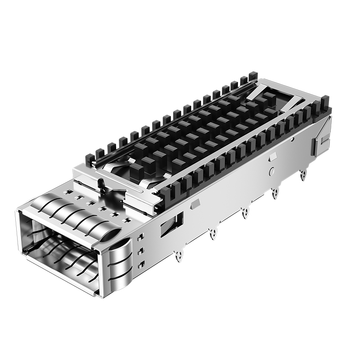
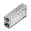
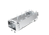
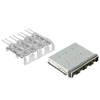

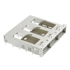






Heatsink height directly affects how a QSFP28 cage fits into a 100G PCB layout. It determines the vertical space required above the board and influences nearby component placement, mechanical clearance, and chassis integration.
QSFP28 is a 100G optical transceiver form factor commonly used in data center switches, routers, and high-speed network equipment. As these devices integrate more ports into limited space, engineers need to consider the cage structure and heatsink dimensions early in the PCB design process.
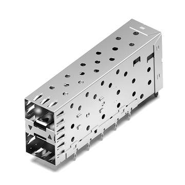
A QSFP28 cage with a heatsink combines a metal enclosure with an external cooling structure. The cage provides mechanical support and EMI shielding, while the heatsink provides a thermal path for dissipating heat from the installed transceiver. Its effectiveness depends on the thermal contact interface, heatsink structure, and surrounding airflow.
One important detail is that heatsink height and overall cage height are different measurements. Understanding these dimensions helps engineers avoid clearance issues during PCB design and mechanical integration.
Understanding QSFP28 Cage Heatsink Height
Heatsink height is an important mechanical dimension when selecting a QSFP28 cage for 100G equipment. It describes the vertical size of the cooling structure and helps determine how much space the assembly needs above the PCB.
Accurate heatsink height measurements provide a reference for calculating vertical clearance in the PCB layout. Since QSFP28 cage assemblies use different cooling structures, engineers should confirm the measurement reference and actual dimensions of each selected model.

Heatsink Height and Measurement Reference
Heatsink height generally refers to the vertical distance from a specified reference surface to the highest point of the heatsink. However, the exact measurement reference depends on the product drawing.
For PCB-mounted cage assemblies, engineers should identify the reference surfaces before comparing different models. A drawing may specify dimensions relative to the PCB surface, cage base, or another mechanical datum.
The following terms help clarify the measurement:
- PCB Reference Plane: The board surface used as a reference for vertical dimensions.
- Heatsink Top Surface: The highest point of the cooling structure.
- Cage Mounting Position: The location where the cage is secured to the PCB.
When reviewing a mechanical drawing, check the dimension arrows and reference labels rather than relying on a product description alone. This prevents confusion between the heatsink's own height and the total height of the assembled component.
Heatsink Height in Product Drawings
QSFP28 cage assemblies are available with different heatsink dimensions to meet the mechanical and thermal requirements of network equipment. The actual height depends on the cage design, cooling structure, and available installation space.
There is no single standard heatsink height for all QSFP28 cage assemblies. The actual dimensions vary depending on the cage structure, heatsink design, and equipment requirements. Engineers should refer to the mechanical drawing of the selected model to confirm its exact heatsink height and measurement reference.
When comparing different models, engineers should check the following dimensions:
- Heatsink Height: The vertical dimension of the cooling structure.
- Heatsink Width: The side-to-side dimension of the heatsink.
- Heatsink Length: The front-to-back dimension of the cooling structure.
Overall Assembly Height: The complete vertical dimension of the cage and its attached components.
These measurements should be checked against the corresponding mechanical drawings. Do not assume that two QSFP28 cages with the same overall height have identical heatsink dimensions.
Heatsink Height vs. Overall Cage Dimensions
Heatsink height describes only one part of the assembly, while overall cage dimensions cover the complete mechanical structure. These measurements serve different purposes during hardware design.
A typical QSFP28 cage assembly may include:
- Cage Body: The metal enclosure that holds and guides the optical transceiver.
- Heatsink: The upper cooling structure designed to help dissipate heat from the installed module.
- Heatsink Attachment: Clips or other fastening features that secure the cooling structure.
- PCB Mounting Features: Pins and other structures used to attach the cage to the circuit board.
These parts contribute to the assembly's total dimensions, but they do not all share the same measurement reference. For example, heatsink height does not include the full depth of the cage or the length of its PCB mounting pins.
The distinction is important when comparing cage models because the overall assembly height does not represent the heatsink's individual dimensions. Always check the specified measurement references before using these values in PCB layout calculations.
How Heatsink Height Affects QSFP28 Cage PCB Layout
The height of a heatsink directly affects the vertical space required above a QSFP28 cage and can influence the placement of nearby components. During 100G hardware design, engineers must consider these dimensions to prevent mechanical conflicts between the cooling structure, PCB components, and chassis.
A taller cooling structure requires more room above the board. Depending on the equipment design, this may affect the position of internal supports, brackets, and other components.
Vertical Space Above the PCB
The heatsink extends above the cage body, creating a vertical space requirement that must be considered during equipment design. Its height determines how much room the cooling assembly occupies between the PCB surface and the surrounding chassis structure.
For example, a heatsink that extends too close to the chassis cover may cause interference when the equipment is assembled. It can also restrict the available space for brackets, internal supports, and other structures above the board.
When evaluating the vertical layout, engineers should consider:
- The distance between the PCB reference plane and the top of the heatsink.
- The available internal height of the equipment enclosure.
- The position of brackets and structural supports above the cage.
- The space needed to install and secure the cooling assembly.
Checking these dimensions together helps ensure that the selected cage fits within the equipment's available vertical space.
Clearance Around Adjacent Components
The heatsink and cage occupy physical space on and above the PCB. Nearby electronic components must be positioned so they do not overlap with the cage structure or interfere with its installation.
This is particularly important in compact 100G switches, where multiple components may be placed close to the front-panel connector area.
Engineers should pay attention to several common layout considerations:
- Component Height: Check whether nearby capacitors, inductors, or other components extend into the heatsink's occupied space.
- Component Position: Keep components outside the cage's defined mechanical footprint and restricted areas.
- Assembly Access: Avoid component placements that obstruct cage installation or heatsink attachment.
The required clearance depends on the cage design and the dimensions of nearby components. Always use the manufacturer's recommended PCB layout and mechanical drawings to establish the actual limits.
Potential Mechanical Interference
Mechanical interference occurs when two parts occupy overlapping physical space or prevent each other from being assembled correctly. In a QSFP28 cage design, this can happen between the heatsink, nearby components, and internal chassis structures.
For example, a heatsink that is too tall may contact an enclosure support, while an incorrectly positioned PCB component may obstruct the cage mounting area. These conflicts can affect assembly accuracy and make equipment maintenance more difficult.
Common interference risks include:
| Potential Conflict | Possible Design Impact |
| Heatsink and chassis cover | Prevents proper enclosure closure |
| Heatsink and internal bracket | Creates insufficient vertical space |
| Cage body and nearby components | Blocks correct cage placement |
| Mounting features and PCB components | Interferes with installation or fixation |
Mechanical checks should cover both the installed position and the assembly process. A design that appears to fit on a two-dimensional PCB layout may still have conflicts when the full three-dimensional structure is assembled.
Reviewing the mechanical envelope of the cage together with the surrounding equipment structure helps identify these problems before assembly.
PCB Space Allocation for QSFP28 Cage Heatsinks
PCB space allocation determines where a QSFP28 cage, its heatsink, and nearby components can be placed on the board. Unlike checking vertical clearance, this step focuses on reserving suitable mounting areas and preventing layout conflicts around the complete assembly.
Component Placement Around the Cage
The area around a QSFP28 cage should be planned according to its mechanical footprint and mounting requirements. Components placed too close to the cage may interfere with its body, mounting pins, or heatsink attachment structure.
When arranging nearby components, engineers should consider the following:
- Keep-Out Area: Reserve the required area around the cage according to its recommended PCB layout.
- Component Positioning: Place capacitors, resistors, and other components outside restricted mounting and mechanical areas.
- Mounting Access: Avoid placing components where they could obstruct cage installation or fastening operations.
Component placement should follow the actual footprint and mechanical drawing rather than an estimated clearance distance. This is particularly important for compact boards with limited space around the front-panel connector area.
Allocating the Heatsink Keep-Out Area
The PCB layout should reserve a suitable keep-out area around the cage and its heatsink. This space helps prevent component placement conflicts and provides room for the complete assembly.
When defining this area, consider:
- Heatsink Footprint: Reserve the board area required by the complete cage structure.
- Component Separation: Keep nearby components outside the specified mechanical boundaries.
- Mounting Access: Allow sufficient room for installing the cage and securing its mounting features.
Use the recommended PCB footprint and mechanical drawing to define the actual keep-out area instead of applying an estimated clearance value.
PCB and Chassis Clearance Limitations
The PCB and chassis form two important mechanical boundaries for a cage assembly. Their relative positions determine how much room is available for the cage body, mounting features, and upper cooling structure.
Several factors can limit the available space:
- PCB Thickness: Affects the vertical reference position of the mounted assembly.
- Board-to-Chassis Distance: Determines the space between the PCB and surrounding enclosure.
- Chassis Opening: Must align with the cage interface to allow proper module insertion and removal.
- Internal Supports: Brackets and mounting structures may restrict the space around the heatsink.
Engineers should evaluate these dimensions as part of the overall mechanical arrangement rather than checking the PCB and chassis separately.
For example, a cage may fit correctly on the PCB but still conflict with an internal chassis support after installation. Reviewing the complete assembly helps identify these limitations before prototype manufacturing.
Multi-Port QSFP28 Cage Layout and Heatsink Spacing

Multi-port QSFP28 cage layouts require careful planning of port positions, heatsink spacing, and PCB mounting areas. In 100G switches and other high-density network equipment, multiple optical ports are often placed close together, making the arrangement of cage assemblies an important part of mechanical design.
Compared with a single-port configuration, a multi-port assembly can occupy a larger PCB area and introduce additional spacing requirements. Engineers should consider the complete cage structure rather than evaluating each port as an isolated component.
Space Requirements for 1×1 and 1×N Cages
QSFP28 cages are available in different port configurations, including 1×1 single-port and 1×N multi-port designs. The number and arrangement of ports affect the overall assembly dimensions and the PCB area required for installation.
A 1×1 cage provides an individual mounting structure for one optical port, while a 1×N design combines multiple ports within a shared assembly. The latter can help organize several connections within a compact front-panel area.
The following table illustrates common port layout examples:
| Layout Configuration | Structural Characteristics | PCB Layout Considerations |
| 1×1 | One independent cage port | Individual footprint and mounting area |
| 1×2 | Two horizontally arranged ports | Shared assembly dimensions and port alignment |
| 1×3 | Three horizontally arranged ports | Wider mounting area and component placement |
| 1×4 | Four horizontally arranged ports | Greater horizontal space and coordinated mounting |
These configurations are layout examples rather than a complete list of available products. The actual dimensions depend on the specific cage design. Engineers should refer to the mechanical drawing instead of calculating the total dimensions by simply multiplying a single-port footprint.
Heatsink Spacing Between Adjacent Ports
When multiple QSFP28 ports are installed side by side, the spacing between their heatsinks becomes an important mechanical consideration. The cooling structures must fit within the available area without interfering with neighboring heatsinks or other equipment components.
Several factors should be checked during layout design:
- Heatsink Width: Confirm the lateral dimensions of each cooling structure and its position relative to adjacent ports.
- Structural Separation: Check whether neighboring heatsinks require physical spacing or use a shared mounting structure.
- Mechanical Clearance: Ensure that clips, retaining features, and other parts do not overlap unintentionally.
- Module Access: Maintain sufficient room for inserting and removing optical transceivers.
The required spacing depends on the cage configuration and heatsink design. Some multi-port assemblies use integrated structures, while others have separate cooling components for individual ports.
Therefore, engineers should evaluate the actual assembly drawing rather than assume that every port requires the same independent clearance.
PCB Layout for High-Density Port Configurations
High-density 100G equipment often needs to accommodate multiple QSFP28 interfaces within a limited front-panel area. This places additional demands on PCB layout because port alignment, mounting locations, and nearby components must work together.
When planning a high-density configuration, consider these design factors:
- Port Arrangement: Determine the number of QSFP28 ports and their horizontal or vertical arrangement according to the equipment design.
- PCB Footprint: Match the board layout to the mounting pattern of the selected multi-port cage.
- Component Distribution: Arrange nearby electronic components around the complete cage assembly and its mounting areas.
- Heatsink Positioning: Check the location and dimensions of each cooling structure to avoid mechanical conflicts.
A compact port arrangement does not automatically provide sufficient cooling space. The heatsink configuration and equipment airflow should also be evaluated to ensure that the mechanical layout does not restrict the intended cooling path.
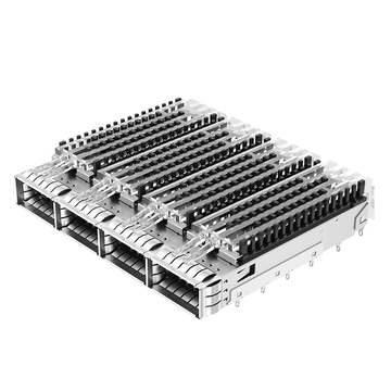
For example, LINK-PP LP14FC01440 is a QSFP28 1×4 cage assembly with an included heatsink, EMI spring fingers, and light pipe. Its four-port arrangement provides a practical reference when evaluating the overall dimensions and mounting layout of a multi-port design. The 77.92mm assembly width and 15.10mm overall height are useful dimensions to check against the intended PCB and chassis layout. For detailed heatsink geometry and dimensions, download the mechanical drawing from the LP14FC01440 product page.
Thermal Design Considerations for QSFP28 Cage Heatsinks
Heatsink height and structure both influence the cooling arrangement of a QSFP28 cage. During PCB design, engineers should consider not only the available space above the board but also the airflow path and thermal conditions around adjacent ports.
In compact switches and routers, multiple optical modules may operate close together and generate heat within a limited space. A suitable cooling design helps manage temperature buildup and maintain stable equipment operation.
Heatsink Structure and Heat Dissipation
The structure of a heatsink affects how heat moves away from the optical module and spreads across the cooling surface. Different designs provide different surface areas and airflow paths, making their selection an important part of thermal management.
Common heatsink structures include:
- Plate-Fin Heatsink: Uses parallel fins to provide an extended surface area for heat transfer.
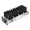
- Pin-Fin Heatsink: Uses an array of pins to provide heat-dissipating surfaces and allow airflow around the pins.
The choice between these structures depends on the equipment's airflow direction, available space, and cooling requirements. Their thermal performance should be evaluated under actual operating conditions rather than judged by appearance alone.
Heatsink height is also one factor in thermal design. A taller structure does not automatically provide better cooling because fin geometry, material, thermal contact, and airflow all affect heat dissipation.
Airflow Space Around the Heatsink
Airflow plays an important role in removing heat from the heatsink surface. Even when a suitable cooling structure is selected, restricted airflow can reduce its ability to transfer heat into the surrounding air.
In 100G switches, fans and internal ventilation paths help move air across the optical module area. The cooling structure should be positioned so that its surfaces receive sufficient airflow.
Engineers should pay attention to the following factors:
- Airflow Direction: Check whether air moves parallel or perpendicular to the heatsink fins.
- Airflow Path: Avoid unnecessary obstructions that restrict air movement around the cooling structure.
- Fan Position: Consider how the location of internal fans affects airflow across the QSFP28 port area.
- Heatsink Orientation: Match the fin or pin arrangement to the intended cooling direction.
For example, a plate-fin heatsink may work differently depending on whether incoming air flows along or across its fins. The cooling structure should therefore be evaluated together with the equipment's actual ventilation design.
Heat Distribution Across Adjacent Ports
Multiple QSFP28 modules installed close together can create overlapping thermal loads within the same equipment area. Heat from neighboring ports may affect local temperatures, particularly when airflow is limited or the equipment operates under heavy traffic.
Several factors can influence the thermal conditions around adjacent ports:
- Module Power Consumption: Modules with different power requirements generate different amounts of heat.
- Port Density: Closely arranged optical interfaces can increase the thermal load within a limited space.
- Heatsink Arrangement: The position and structure of neighboring cooling components affect heat transfer.
- Airflow Distribution: Uneven airflow can cause some ports to experience higher temperatures than others.
A practical thermal assessment should examine individual module temperatures and nearby areas under representative operating conditions. Engineers can use temperature sensors and thermal testing to identify potential hotspots.
The goal is not simply to install a larger heatsink on every port, but to achieve a suitable balance between cooling capacity, available space, and airflow distribution across the entire QSFP28 port area.
QSFP28 Cage Heatsink Height: Design Verification
Verifying heatsink height and mechanical dimensions before PCB manufacturing helps prevent installation conflicts in 100G network equipment. Engineers should compare the cage dimensions with the actual PCB layout and chassis structure to confirm that all components fit together correctly.
A complete verification process involves reviewing mechanical drawings, checking PCB mounting details, and confirming the position of the heatsink after assembly. These checks help identify potential problems before they affect prototype testing or production.
Review Mechanical Drawings and Dimensions
Mechanical drawings provide the dimensions and structural details needed to evaluate a QSFP28 cage before selecting or integrating it. They help engineers understand the relationship between the cage body, heatsink, mounting features, and surrounding structures.
When reviewing a product drawing, pay attention to the following details:
- Heatsink Height: Confirm the vertical dimension and its measurement reference.
- Overall Dimensions: Check the cage width, length, and total assembly height.
- Mounting Features: Identify the position and dimensions of PCB mounting pins, holes, and other fastening structures.
- Mechanical Tolerances: Review specified tolerances to account for dimensional variations during manufacturing.
For multi-port assemblies, also check the complete structure rather than relying on the dimensions of an individual port. This helps ensure that the selected configuration matches the intended equipment layout.
Verify PCB Footprint and Component Clearance
After confirming the mechanical dimensions, compare the recommended PCB footprint with the actual board design. The mounting pattern must match the cage structure to ensure correct positioning and secure attachment.
Several areas require attention during this process:
- Mounting Hole Alignment: Check that PCB holes and mounting locations match the cage's pin arrangement.
- Footprint Dimensions: Confirm that the board layout follows the recommended dimensions and tolerances.
- Component Clearance: Review nearby components to ensure they do not overlap with the cage body or its mounting features.
- PCB Thickness: Verify that the board thickness meets the product's mounting requirements.
For example, the LINK-PP LP11FC01250M and LP14FC01440 both use a recommended PCB thickness of 1.60mm. This provides a useful reference when reviewing board specifications, but the complete mounting drawing should still be checked against the actual PCB design.
Confirm Chassis and Heatsink Alignment
The final verification step is to check how the cage and heatsink fit within the complete equipment enclosure. A design that meets PCB mounting requirements may still encounter problems when combined with the front panel, internal supports, or chassis cover.
Engineers should confirm three important areas:
- Front Panel Alignment: Ensure that the cage opening matches the equipment's front-panel cutout and allows proper module insertion and removal.
- Heatsink Clearance: Check that the cooling structure does not contact the chassis cover, brackets, or other internal components.
- Assembly Position: Confirm that the cage remains correctly positioned after PCB installation and enclosure assembly.
A 3D mechanical model can help identify potential conflicts before physical prototypes are built. For more complex designs, a physical fit check can provide additional confirmation of the actual assembly conditions.
Before finalizing the PCB design, review the mechanical drawing, footprint, and enclosure layout together. This provides a more reliable basis for confirming that the selected cage is suitable for the intended 100G equipment.
LINK-PP QSFP28 Cages for PCB Integration
After defining the mechanical and installation requirements, comparing actual cage configurations can help narrow down suitable options. LINK-PP offers several QSFP28 cage models with integrated heatsinks for different PCB layouts and port arrangements.
LINK-PP LP11FC01030: Compact 1×1 Cage Design
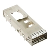
For PCB layouts where vertical space is a priority, the LINK-PP LP11FC01030 offers a compact single-port QSFP28 cage configuration.
This model integrates a heatsink with an EMI spring finger structure and uses Press-Fit mounting for PCB installation. Its overall cage assembly height is 9.65mm, making it a useful option to evaluate when the available space above the board is limited.
The compact overall profile is its main design advantage. Engineers can consider this configuration when planning single-port 100G interfaces in equipment with restricted vertical space, while checking the detailed heatsink dimensions and required clearance in the mechanical drawing.
LINK-PP LP11FC01250M: 1×1 Cage with Integrated Heatsink and Light Pipe
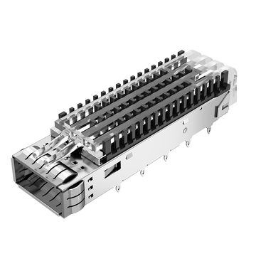
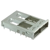
When a single-port design also requires front-panel status indication, the LINK-PP LP11FC01250M provides an integrated cage, heatsink, and light pipe configuration.
Its Press-Fit mounting structure and EMI spring fingers support PCB and chassis integration, while the included light pipe provides a path for displaying equipment status through the front panel.
With an overall cage assembly height of 16.00mm, this model is particularly relevant when engineers need to coordinate the vertical space occupied by the cooling structure and the light pipe assembly. The complete mechanical drawing should be reviewed to confirm the required installation envelope.
LINK-PP LP14FC01440: 1×4 Cage for High-Density 100G Ports
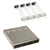
For hardware designs requiring four QSFP28 interfaces in one horizontal row, the LINK-PP LP14FC01440 offers an integrated 1×4 cage assembly with a heatsink.
Its 77.92mm overall width and 15.10mm overall height provide useful reference dimensions for planning a multi-port PCB layout. The integrated structure also combines the cage, heatsink, EMI spring fingers, and light pipe, helping designers coordinate several port positions within one assembly.
Unlike the two single-port options, its main advantage is the four-port configuration. It is worth considering for 100G switches and other equipment where multiple QSFP28 connections need to be arranged along a shared front-panel section.
The following table summarizes their main differences:
| LINK-PP QSFP28 Cages | Port Configuration | Overall Cage Assembly Height | Main Design Advantage |
| LP11FC01030 | 1×1 | 9.65mm | Compact single-port profile |
| LP11FC01250M | 1×1 | 16.00mm | Single-port integration with light pipe |
| LP14FC01440 | 1×4 | 15.10mm | Four-port integrated layout |
Important: The listed heights refer to the overall cage assembly dimensions, not the heatsink-only height. All three models include a heatsink and do not include an electrical connector. The exact heatsink profile, mounting dimensions, and PCB requirements should be confirmed using the corresponding product drawings.
These three configurations address different design priorities: limited vertical space, single-port integration with status indication, and high-density four-port placement. Comparing their mechanical structures helps engineers narrow down suitable options before completing PCB and thermal design.
These models provide different mechanical configurations for PCB integration. Before selecting one, compare the heatsink dimensions, mounting footprint, and available chassis space using the corresponding product drawings.
Matching QSFP28 Cage Heatsink Height to PCB Design

Matching QSFP28 cage heatsink height to the PCB layout helps prevent mechanical interference and supports a suitable cooling arrangement. Engineers should evaluate the heatsink dimensions, component clearance, mounting footprint, and chassis space together before finalizing the board design.
Key considerations include:
- Heatsink Dimensions: Check the height and overall dimensions against the available installation space.
- PCB Layout: Confirm the footprint, mounting positions, and clearance around nearby components.
- Port Configuration: Match the cage structure and heatsink arrangement to the required port density.
- Thermal Requirements: Evaluate heatsink design and airflow under actual operating conditions.
- Mechanical Compatibility: Verify the complete assembly using product drawings and equipment models.
A well-matched cage helps simplify PCB integration and reduces potential mechanical and thermal design conflicts. For suitable QSFP28 cage options, product specifications, and technical assistance, visit the LINK-PP Official Store or contact our sales team for further support.