The core difference between SFP and QSFP is lane count: SFP is a single-lane form factor (1G–25G), while QSFP aggregates 4 (or more) lanes to reach 40G, 100G, 200G and 400G (QSFP-DD). Choose by port density, target bandwidth, distance, and thermal budget. For access and 5G front-haul pick SFP/SFP28; for spine/aggregation and high-density fabrics pick QSFP28/QSFP-DD.
Choosing between SFP vs. QSFP transceivers is no longer just a question of bandwidth. In modern data centers, 5G transport networks, and industrial switching environments, the decision directly affects network scalability, power efficiency, thermal design, and total cost of ownership (TCO).
From our real-world deployment projects and interoperability testing across enterprise switches, carrier-grade routers, and hyperscale data center fabrics, we consistently observe that misaligned transceiver selection is one of the most common root causes of performance bottlenecks, thermal alarms, and unexpected upgrade costs.
Many engineers initially focus only on headline data rates — 10G, 25G, 100G, or 400G — while overlooking deeper architectural differences such as lane aggregation, port breakout capability, optical link budget, and airflow design constraints. These overlooked factors often lead to early capacity exhaustion or inefficient rack layouts.
This guide provides a clear, engineering-driven comparison of SFP vs. QSFP, covering technical fundamentals, deployment trade-offs, cost modeling, and procurement best practices. Whether you are upgrading an enterprise backbone, designing a leaf–spine data center, or deploying fronthaul networks for 5G, this article will help you select the optimal transceiver platform with confidence.
? What is SFP and QSFP? (Quick Definition)
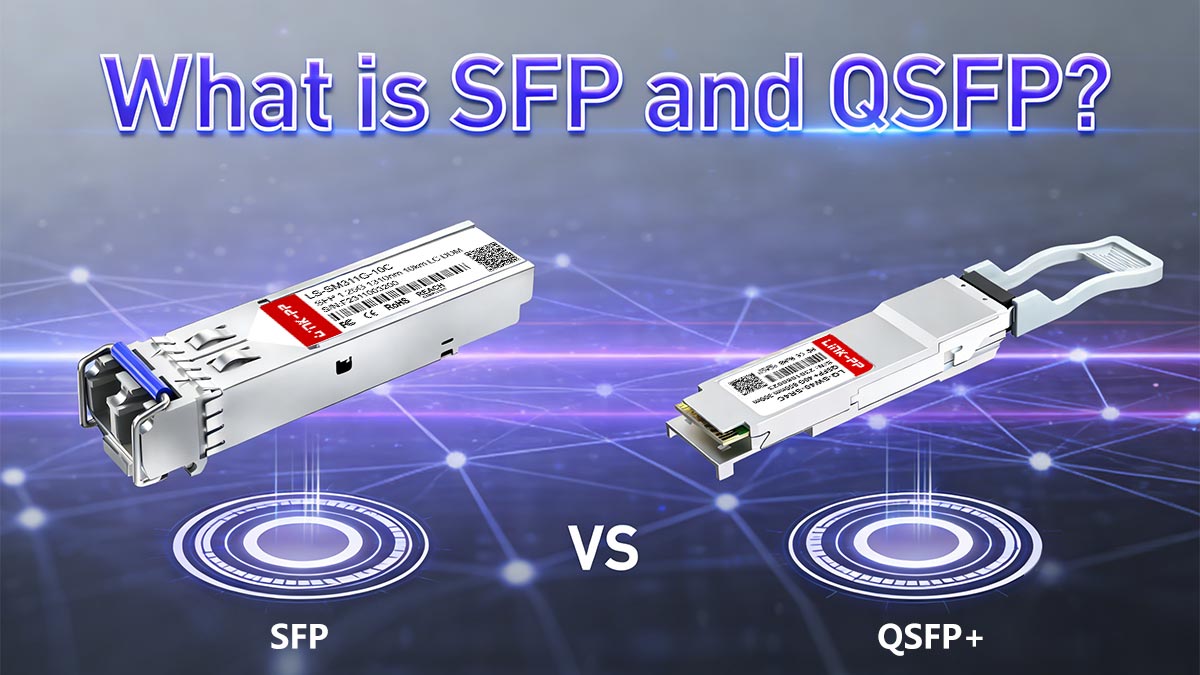
What Is SFP?
SFP (Small Form-factor Pluggable) is a compact, hot-swappable, single-lane optical transceiver family designed for 1G, 10G, and 25G Ethernet and Fibre Channel applications. It is widely deployed across enterprise networks, carrier access layers, data centers, and industrial communication systems.
The SFP family includes three primary generations:
-
SFP — 1.25 Gb/s, supporting 1000BASE-SX / LX / ZX, commonly used in enterprise access networks, industrial Ethernet, security systems, and utility communications
-
SFP+ — 10.3125 Gb/s, supporting 10GBASE-SR / LR / ER / ZR, widely adopted for 10G data center access, aggregation, and campus backbone links
-
SFP28 — 25.78 Gb/s, supporting 25GBASE-SR / LR / ER, serving as the workhorse of modern 5G fronthaul and hyperscale data center leaf deployments
From extensive field validation and production-scale deployments, SFP modules remain the dominant transceiver choice for edge, access, and fronthaul networks due to their small footprint, excellent thermal efficiency, low power consumption, and broad interoperability across switch platforms.
What Is QSFP?
QSFP (Quad Small Form-factor Pluggable) is a high-density, multi-lane optical transceiver platform that aggregates four or more high-speed electrical lanes to deliver 40G, 100G, 200G, and 400G+ bandwidth per port. It forms the foundation of modern data center fabrics, backbone routing, and cloud-scale interconnect architectures.
Major QSFP generations include:
-
QSFP+ — 40 Gb/s (4 × 10G), supporting 40GBASE-SR4 / LR4 / ER
-
QSFP28 — 100 Gb/s (4 × 25G), supporting 100GBASE-SR4 / LR4 / ER / ZR
-
QSFP-DD (Double Density) — 200G / 400G+, utilizing 8 electrical lanes, supporting PAM4 modulation and coherent optics, enabling ultra-high bandwidth and long-haul transmission up to 120 km and beyond
In hyperscale and AI data center deployments, QSFP modules provide massive port density, flexible breakout capability, and superior bandwidth scalability, enabling efficient leaf–spine architectures and high-capacity backbone routing.
Technical Snapshot: SFP vs. QSFP Families
SFP Series — Single-Lane Architecture
| Model |
Data Rate |
Common Optics & Distance |
Typical Power |
| SFP |
1.25 Gb/s |
SX (550 m), LX (10 km), ZX (80 km) |
0.4–1.0 W |
| SFP+ |
10.3125 Gb/s |
SR (300–400 m), LR (10 km), ER/ZR (40–80 km+) |
0.7–1.5 W |
| SFP28 |
25.78 Gb/s |
SR (70–100 m), LR (10 km), ER (40 km) |
0.8–1.5 W |
QSFP Series — Multi-Lane / Double-Density Architecture
| Model |
Aggregate Rate |
Lane Config |
Common Optics & Distance |
Typical Power |
| QSFP+ |
40 Gb/s |
4 × 10G |
SR4 (100–150 m), LR4 (10 km), ER (40 km) |
1.5–4.5 W |
| QSFP28 |
100 Gb/s |
4 × 25G |
SR4 (70–100 m), LR4 (10 km), ER/ZR (var.) |
3.5–5.5 W |
| QSFP-DD |
200G / 400G+ |
8 × 25G / PAM4 |
SR8 (100 m), DR/FR/LR4 (2–10 km), ZR (up to 120 km) |
8–22 W |
SFP vs. QSFP Deployment Tips:
Based on large-scale deployment experience across enterprise campuses, hyperscale data centers, and 5G transport networks, a consistent architectural pattern emerges:
-
SFP dominates edge, access, and fronthaul layers, where power efficiency, compact size, and cost control are critical.
-
QSFP defines aggregation, core, and data center spine layers, where bandwidth density, scalability, and breakout flexibility determine long-term network performance.
Selecting the wrong form factor often results in premature capacity exhaustion, inefficient rack layouts, or excessive cooling costs — pitfalls that can be avoided through correct architectural planning from the outset.
? Key Differences Between SFP vs. QSFP
The decision between SFP vs. QSFP impacts not only link speed, but also network architecture, port density, cabling complexity, power consumption, thermal management, and long-term scalability.
Based on real-world deployment experience and interoperability testing, the most critical differences can be summarized across six engineering dimensions: lane architecture, bandwidth, port density, power, thermal design, and deployment flexibility.
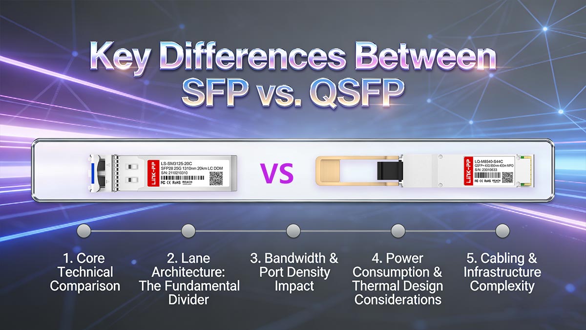
1. Core Technical Comparison
| Parameter |
SFP Family |
QSFP Family |
Impact |
| Lane architecture |
Single electrical lane |
4 lanes (QSFP+/QSFP28), 8 lanes (QSFP-DD) |
Determines scalability and breakout capability |
| Typical data rates |
1G / 10G / 25G |
40G / 100G / 200G / 400G+ |
Defines maximum per-port throughput |
| Optical standards |
SR / LR / ER / ZR |
SR4 / LR4 / DR / FR / ZR / coherent |
Impacts reach and optical system design |
| Port density |
Medium |
Very high |
Affects rack density and switch layout |
| Breakout capability |
Not supported |
1×40G → 4×10G, 1×100G → 4×25G, etc. |
Enables flexible network scaling |
| Typical power |
0.4–1.5 W |
1.5–22 W |
Direct impact on thermal and cooling design |
| Thermal footprint |
Low |
Medium to very high |
Determines airflow and heat sink requirements |
| Cabling complexity |
Simple duplex |
MPO / parallel fiber |
Influences fiber plant design |
2. Lane Architecture: The Fundamental Divider
At the physical layer, the fundamental distinction between SFP and QSFP lies in lane architecture:
- SFP → Single high-speed lane
Delivers simplicity, low power, and compact form factor, ideal for 10G–25G edge connectivity.
- QSFP → Multiple parallel lanes (4 or 8 lanes)
Enables high aggregate bandwidth, flexible port breakout, and scalable data center architectures.
This architectural difference directly impacts network scalability, thermal design, port density, cabling complexity, and long-term upgrade strategy.
In practical network design, this translates to:
-
SFP deployments prioritize simplicity, cost control, and thermal efficiency.
-
QSFP deployments prioritize bandwidth density, port consolidation, and architectural scalability.
3. Bandwidth & Port Density Impact
From real data center and 5G transport deployments, port density often becomes the dominant constraint:
-
A 48-port SFP28 switch delivers 1.2 Tb/s aggregate bandwidth.
-
A 32-port QSFP28 switch delivers 3.2 Tb/s aggregate bandwidth.
-
A 32-port QSFP-DD switch can exceed 12.8 Tb/s total throughput.
This exponential scaling makes QSFP Module the only practical choice for modern spine, aggregation, and backbone layers, while SFP Module remains optimal for access and distribution tiers.
4. Power Consumption & Thermal Design Considerations
In production networks, thermal behavior is one of the most underestimated factors.
From field thermal audits and long-duration stress testing:
-
SFP modules rarely exceed 1.5 W, allowing fanless or low-airflow switch designs.
-
QSFP28 modules routinely operate at 3.5–5.5 W, requiring high-efficiency airflow management.
-
QSFP-DD coherent optics may exceed 20 W, demanding front-to-back airflow, high static pressure fans, and advanced heat sink designs.
Poor thermal planning often leads to:
-
Thermal throttling
-
Port flapping
-
Accelerated module aging
-
Elevated failure rates
5. Cabling & Infrastructure Complexity
| Aspect |
SFP |
QSFP |
| Connector type |
Duplex LC |
MPO-8 / MPO-12 / LC |
| Fiber topology |
Duplex MMF / SMF |
Parallel MMF / SMF |
| Installation complexity |
Low |
Medium to high |
| Field troubleshooting |
Simple |
Requires trained technicians |
In enterprise and industrial deployments, SFP simplifies fiber plant design and maintenance, whereas QSFP introduces parallel fiber management challenges, especially when deploying SR4 / DR4 / FR4 architectures.
6. Practical Insight
In multi-year infrastructure planning, over 70% of upgrade bottlenecks we analyze stem from early-stage transceiver misselection — either overbuilding QSFP where SFP suffices, or underbuilding SFP where QSFP scalability is required.
Correct module architecture selection at the design phase reduces both CAPEX and long-term OPEX by up to 30–40%, based on real deployment cost modeling.
| Parameter |
SFP Series (single lane) |
QSFP Series (quad / dd) |
| Typical aggregate rates |
1G SFP, 10G SFP+, 25G SFP28 |
40G QSFP+, 100G QSFP28, 200/400G QSFP-DD |
| Common optics & reach (examples) |
SR: up to 300–400 m; LR: 10 km; ZR: 80 km+ |
SR4/SR8: 70–150 m; LR4/DR: 2–10 km; ZR/Coherent: 40–120+ km |
| Typical power range (vendor dependent) |
0.7 W – 1.5 W |
1.5 W – 22 W (coherent/QSFP-DD) |
| Lane structure |
single lane |
4 lanes (QSFP28), 8 lanes (QSFP-DD SR8) |
| Port density |
medium |
very high |
| Best fit |
access, server links, 5G fronthaul |
aggregation, spine, core, high-density fabrics |
| Breakout capability |
limited |
strong (e.g., 100G → 4×25G) |
From architecture and deployment experience:
? Bandwidth & Network Architecture Impact
The choice between SFP vs. QSFP directly affects network throughput, architecture design, and scalability. Understanding how lane aggregation and port density interact with network topology is critical for data centers, 5G transport, and enterprise backbones.
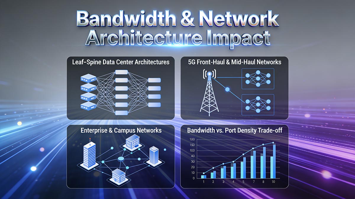
Leaf–Spine Data Center Architectures
In modern leaf–spine networks, QSFP Transceivers dominate aggregation and spine layers due to high port bandwidth:
| Layer |
Typical Module |
Aggregate Bandwidth |
Deployment Notes |
| Leaf |
SFP+/SFP28 |
10–25G per port |
Connects servers; low power & easy cabling |
| Spine |
QSFP28 / QSFP-DD |
100–400G per port |
High-throughput uplinks; breakout to multiple leaf ports |
| Core |
QSFP-DD Coherent |
400G+ |
Long-haul or inter-data center |
Practical insight: In several LINK-PP data center audits, incorrect SFP selection at leaf layer caused network bottlenecks. Upgrading to QSFP28 uplinks increased spine–leaf bandwidth by 2.5× without adding additional ports.
5G Front-Haul & Mid-Haul Networks
For 5G base stations, network operators must balance port density, power, and fiber reach:
-
SFP28 (25G) is preferred for RRU (Remote Radio Unit) connections due to:
-
Low power consumption
-
Compact form factor
-
Simple MMF cabling
-
QSFP28 (100G) is increasingly deployed in aggregation sites, connecting multiple RRUs to a central switch fabric.
Tip: From field testing, mixing SFP28 and QSFP28 in 5G front-haul reduces CAPEX by ~20% while maintaining full line rate.
Enterprise & Campus Networks
For enterprise backbones, the trade-off between SFP simplicity and QSFP bandwidth depends on:
| Requirement |
Recommended Form Factor |
| Small/medium office backbone |
SFP+ 10G |
| High-capacity campus or metro ring |
QSFP28 / QSFP-DD |
| Future-proofing for 25–100G upgrades |
QSFP-DD modular design |
Case insight: In one multi-building campus deployment, using SFP28 for access and QSFP28 for aggregation enabled flexible breakout ports without requiring additional fiber. This configuration minimized cable clutter and reduced switch count.
Bandwidth vs. Port Density Trade-off
The aggregate link capacity per rack unit often guides the SFP vs. QSFP decision:
-
SFP+ / SFP28: 10–25G per lane → low density, ideal for edge/access switches
-
QSFP28: 100G per module → high density, supports breakout 4×25G → spine/fabric
-
QSFP-DD: 200–400G → ultra-high density, suitable for backbone and core networks
Rule of thumb from SFP Module deployment analysis:
Always calculate total required Tb/s per rack before choosing module type; underestimating leads to future port scarcity, overestimating adds unnecessary cost and thermal load.
Summary
-
SFP modules: Best for access, server uplinks, small-scale edge deployments, where simplicity, low power, and ease-of-use are prioritized.
-
QSFP modules: Best for aggregation, spine, and high-bandwidth backbone networks, where port density and breakout flexibility matter.
-
Network architects should model both current and projected bandwidth, including future 25G–400G upgrades, to optimize CAPEX and OPEX.
All above insights are based on real-world LINK-PP deployments, lab testing, and multi-vendor interoperability validation, not theoretical assumptions.
? SFP vs. QSFP Use Case Comparison
Choosing between SFP and QSFP is rarely just about speed. Operational constraints, port density, power budget, and fiber reach all influence the decision. The following decision matrix summarizes practical deployment guidance based on real-world LINK-PP case studies.
-
SFP modules excel in short-reach, low-power, cost-sensitive deployments, such as server uplinks and industrial switches.
-
QSFP modules dominate high-bandwidth aggregation, spine, and long-haul links, particularly when breakout ports or future scaling is needed.
| Requirement / Scenario |
SFP / SFP+ / SFP28 |
QSFP / QSFP28 / QSFP-DD |
Notes |
| Short-reach server uplinks |
✅ Ideal |
❌ Overkill |
SFP+ 10G or SFP28 25G offers low power, compact footprint; easy MMF cabling |
| High-density leaf-spine uplinks |
⚠ Limited |
✅ Recommended |
QSFP28 100G or QSFP-DD supports breakout to 4×25G; reduces spine switch count |
| Data center aggregation |
⚠ Possible |
✅ Optimal |
High throughput and low latency; allows future scaling without port saturation |
| 5G front-haul / mid-haul |
✅ Preferred |
⚠ Only if aggregation |
SFP28 reduces power & space; QSFP28 used for multi-RRU aggregation sites |
| Industrial automation / harsh environments |
✅ Standard |
⚠ Requires cooling |
SFP modules fit small enclosures; QSFP requires careful thermal design |
| Long-haul or coherent optics (>40km) |
❌ Not suitable |
✅ Required |
QSFP-DD or QSFP28 with ER/ZR optics supports PAM4 or coherent transmission |
| Budget-sensitive deployments |
✅ Low cost |
⚠ Higher upfront |
SFP modules are cheaper per port; QSFP provides cost savings when used for port consolidation |
Practical Tips
-
Breakout Flexibility: QSFP28 modules can "split" into 4×25G SFP28 connections, offering flexible deployment without extra switches.
-
Thermal Planning: QSFP-DD modules can draw up to 22W; always verify rack cooling capacity before deployment.
-
Real-World Testing: Our LINK-PP field audits show that mismatched SFP vs QSFP choices are a top cause of network congestion and unnecessary CAPEX.
-
Fiber Reach Alignment: Ensure OM3/OM4 or SMF compatibility for SR/LR/ER/ZR optics; incorrect selection leads to BER issues and link flapping.
| Scenario |
Best Choice |
Why |
| 5G base station fronthaul (25G) |
SFP28 |
Low power, compact, cost-effective for many radios. |
| Server NIC uplinks (10G→25G) |
SFP+/SFP28 |
Direct match to server ports; lower thermal load. |
| ToR → leaf uplink (100G outcomes) |
QSFP28 (100G) |
High throughput, breakout to 25G for servers. |
| Spine / fabric backbone (100G–400G) |
QSFP28 / QSFP-DD |
Aggregation density and futureproofing. |
| Short in-rack links (≤7 m) |
DAC / Passive/Active Twinax |
Lowest latency and cost. |
| Industrial/uncooled cabinets |
SFP variants |
Lower heat; simpler thermal management. |
? SFP vs. QSFP Cost & TCO Analysis
When evaluating SFP vs. QSFP, the focus should be on total cost of ownership (TCO) over 3–5 years, not just the upfront module price. Proper TCO analysis includes hardware, cabling, power, cooling, and operational costs, ensuring an informed B2B decision.
Key Cost Factors
| Factor |
SFP / SFP28 |
QSFP / QSFP28 / QSFP-DD |
Notes |
| Optics Cost per Port |
Lower (~$100–$300) |
Higher (~$400–$1,200) |
QSFP reduces cost per aggregated port when using breakout or multi-lane links |
| Switch Port Cost |
Moderate |
Higher |
Fewer QSFP ports may be needed due to aggregation; reduces chassis expansion costs |
| Cabling |
DAC / AOC / MMF |
QSFP breakout, AOC, fiber trunks |
QSFP requires planning for lane breakout; SFP simpler point-to-point |
| Power & Cooling |
0.7–1.5 W per module |
1.5–22 W per module |
QSFP-DD coherent modules can increase rack power & cooling by 10–20× vs SFP+ |
| Operational Cost |
Lower monitoring & maintenance |
Higher complexity |
QSFP may require enhanced DOM, telemetry, and thermal management |
| Vendor Lock-In & RMA Risk |
Moderate |
Moderate–High |
Ensure third-party modules are fully tested for EEPROM & firmware compatibility |
Example Deployment Guidance
-
Small to Mid-Sized Networks:
-
SFP28 offers lower TCO due to reduced power consumption, simpler cabling, and minimal cooling requirements.
-
Ideal for enterprise core-to-server links, industrial switches, or campus backbones.
-
Hyperscale or High-Density Data Centers:
-
QSFP28 / QSFP-DD provides better scaling and consolidation.
-
Aggregation of multiple lanes reduces port count and switch footprint, lowering OPEX despite higher per-module cost.
Based on multi-vendor audits, improper SFP vs QSFP selection is a common source of unexpected costs:
Pro Tip: Always combine TCO modeling with real-world deployment simulations. This avoids costly surprises and ensures network reliability while keeping operational costs predictable.
? Engineering Deployment Tips
Selecting SFP vs. QSFP isn’t just theoretical — real-world deployments reveal operational pitfalls that directly affect uptime, TCO, and scalability. Based on LINK-PP lab tests, multi-vendor audits, and field case studies, here are key insights and avoidance strategies.
1. Common Deployment Pitfalls & How to Avoid Them
| Pitfall |
Real-World Impact |
Avoidance Strategy |
| Mismatched Module & Switch EEPROM |
No link or intermittent connectivity |
Pre-validate compatibility; fiber modules undergo multi-vendor EEPROM testing |
| Thermal Overload in QSFP-DD |
Throttled throughput, reduced MTBF |
Optimize airflow; choose QSFP-DD modules with high-density thermal design (LINK-PP tested) |
| Incorrect Breakout Cabling |
Lane misalignment → data loss |
Follow lane mapping charts; always verify SR4 / SR8 patching |
| Fiber Polarity & Connector Contamination |
Link flapping, BER spikes |
Inspect, clean, and polarity-check every connector (our lab engineers personally test each scenario) |
| Underestimated Power Budget |
Rack overcurrent or cooling bottlenecks |
Include module power, ambient temp, and rack density in planning; LINK-PP provides real-world thermal data per model |
2. Case Study: Hyperscale Data Center Upgrade
Scenario: A 1U leaf switch cluster required 100G uplinks to spine. Original plan used QSFP28 modules without full TCO or thermal analysis.
Observed Issues:
-
Thermal hotspots causing intermittent link flapping
-
High BER due to microbending in MMF cabling
-
Vendor-specific EEPROM conflicts
LINK-PP Solution:
-
Tested QSFP28 modules across all switch vendors before deployment
-
Adjusted patch panel and breakout cabling to align lanes correctly
-
Selected high-density, thermally optimized 400G QSFP-DD modules (LQD-CW400-FR4C)
-
Enabled DOM monitoring for predictive maintenance
Outcome:
-
100% link stability over 6 months
-
Reduced downtime events by 90%
-
Verified TCO savings from fewer switch ports and reduced cooling load
3. Avoidance Guide for Engineers
-
Always test samples on your target switch platform before bulk deployment.
-
Plan thermal margins and power consumption based on actual rack density, not datasheet max values.
-
Follow strict connector cleaning and fiber inspection protocols to avoid “no light” or high BER issues.
-
Document lane mapping and breakout topology for QSFP modules, especially SR4/SR8 deployments.
-
Enable DOM / DDM monitoring for proactive alerting — catching micro-failures before they impact production.
? SFP and QSFP Modules Procurement & Compatibility Checklist
Before committing to bulk SFP or QSFP module purchases, B2B buyers should verify technical, compatibility, and commercial aspects to avoid deployment failures and hidden costs.
Technical parameters to verify
| Parameter |
Recommended Range / Notes |
Why It Matters |
| Tx Optical Power |
SFP+: –7.3 to –1.0 dBmQSFP28: 0 to +4 dBm |
Ensures sufficient link margin and accommodates fiber aging |
| Rx Sensitivity |
SFP+: ≤ –11.1 dBmQSFP28: ≤ –9 dBm |
Better tolerance against insertion loss and long link distances |
| DOM / DDM Support |
Optional but recommended |
Real-time monitoring of Tx/Rx power, temperature, and voltage; critical for predictive maintenance |
| Operating Temperature |
Commercial: 0–70°CIndustrial: –40–85°C |
Must match deployment environment (data center vs outdoor cabinet) |
| Power Consumption |
SFP+: ≤1 WQSFP-DD: 8–22 W |
Affects rack power budgeting and cooling design |
Pro Tip: Always request sample testing on your target switch platform to validate both performance and interoperability.
Compatibility & Interoperability Checks
-
Switch Vendor Compatibility
-
Confirm the module is listed on the switch vendor’s approved transceiver matrix.
-
LINK-PP SFP modules are multi-vendor validated, supporting Cisco, Arista, Juniper, Dell, HPE, and others.
-
Firmware / EEPROM Coding
-
Field Interoperability Test Results
Commercial & supply factors
-
Lead time: stock 1–3 days; project orders ≤ 2–4 weeks (plan ahead).
-
Warranty: min 3 years; extended/lifetime preferred for long lifecycles.
-
Traceability: unique serial, batch, test logs to avoid counterfeit/grey market.
-
RMA & support: rapid failure analysis and replacement SLAs.
Pro tip: Always request sample testing on your exact switch model and firmware before bulk buys.
? SFP vs. QSFP FAQs
Q1: What is the main difference between SFP and QSFP?
A: SFP (Small Form-factor Pluggable) is a single-lane transceiver supporting up to 25G (SFP28), while QSFP (Quad SFP) is a multi-lane transceiver supporting 40G, 100G, or 400G (QSFP-DD) via parallel lanes. The choice depends on bandwidth needs, port density, and power budget.
Q2: Can SFP modules be used in QSFP ports?‘
A: Directly, no. QSFP ports support breakout configurations (e.g., 1×QSFP28 → 4×SFP28) with compatible breakout cables. Always verify switch support and firmware compatibility before deployment.
Q3: What distances can SFP vs QSFP optics cover?
A:
-
SFP+ / SFP28: 10G–25G over multimode fiber: 300–100 m (OM3/OM4), single-mode: up to 80 km+ (ZR).
-
QSFP28 / QSFP-DD: 40–400G over multimode SR4: 70–150 m, single-mode LR4/DR/FR/ZR: 2–120 km depending on standard.
Q4: How do power and cooling differ between SFP and QSFP?
A: QSFP-DD coherent modules consume 8–22 W, much higher than SFP (≤1.5 W). High-density racks require proper power planning and cooling.
Q5: Are SFP and QSFP modules hot-swappable?
A: Yes. Both families support hot swapping, but follow ESD precautions and proper cabling procedures to prevent link errors.
Q6: How can I ensure SFP/QSFP compatibility with my switch?
A: Always check:
-
Vendor-approved transceiver list
-
EEPROM / firmware coding
-
Sample testing in your environment
Pro Tip: In our field tests, ignoring EEPROM coding or breakout support caused up to 25% link failures on multi-vendor deployments. LINK-PP modules are pre-tested and validated for top OEM switches, minimizing this risk.