A 10GBASE-SR SFP module, also called 10G SFP+ SR, is a 10 Gbps multimode optical transceiver using 850 nm VCSEL laser technology and duplex LC connectors, designed for short-reach fiber links over OM3 and OM4 multimode fiber, typically up to 300–400 meters.
As enterprise networks, cloud data centers, and high-performance computing environments continue to scale, 10 Gigabit Ethernet (10GbE) remains one of the most widely deployed link speeds. At the center of these short-reach fiber connections is the 10GBASE-SR SFP module, commonly referred to as 10G SFP+ SR optics.
But what exactly is 10GBASE-SR, how does it work, and when should it be used instead of alternatives like 10GBASE-LR or Direct Attach Copper (DAC)?
In simple terms, 10GBASE-SR is an IEEE-standardized short-reach optical interface designed to deliver 10 Gbps Ethernet transmission over multimode fiber (MMF) using 850 nm VCSEL laser technology. It is optimized for high-density switching environments, providing a cost-effective, low-power, and highly interoperable solution for distances up to 300–400 meters.
Today, 10G SFP+ SR transceivers are the dominant choice for:
-
Top-of-rack (ToR) switch uplinks
-
Server-to-switch fiber links
-
Aggregation and access layer switching
-
Campus backbone fiber interconnects
-
Intra–data center optical connections
Their excellent balance of cost, performance, power efficiency, and ecosystem compatibility makes SFP+ 10G SR the default optical interface for short-range 10GbE deployments.
However, despite their widespread adoption, many engineers and procurement teams still encounter practical challenges such as:
-
Selecting the correct fiber type (OM3 vs OM4)
-
Understanding optical reach limitations
-
Avoiding polarity and connector issues
-
Troubleshooting no-link and high BER conditions
-
Ensuring cross-vendor compatibility
This complete technical guide explains what a 10GBASE-SR SFP module is, how it works, and how to deploy it correctly, covering:
-
Optical architecture and signal encoding
-
Technical specifications and performance limits
-
Deployment best practices
-
Common troubleshooting workflows
-
Procurement and compatibility validation
Whether you are designing a new 10GbE network, upgrading legacy infrastructure, or validating transceiver interoperability, this article provides clear, engineering-focused insights to help you make informed decisions and deploy reliable 10G fiber links with confidence.
⏩ What Is a 10GBASE-SR SFP Module?
A 10GBASE-SR SFP module is a small form-factor pluggable plus SFP+ optical transceiver that implements the IEEE 802.3ae 10GBASE-SR standard, enabling 10 Gigabit Ethernet (10GbE) transmission over multimode fiber (MMF).
It operates at a nominal line rate of 10.3125 Gbps using 850 nm VCSEL laser technology and a duplex LC interface, supporting short-reach fiber links up to 300 m on OM3 and 400 m on OM4 multimode fiber. Designed for high-density and cost-sensitive environments, 10GBASE-SR offers an optimal balance of performance, power efficiency, and interoperability, making it the most widely deployed optical interface for 10GbE networks.
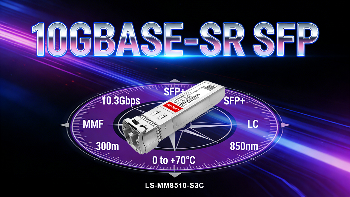
Key Characteristics
-
Standard: IEEE 802.3ae — 10GBASE-SR
-
Data rate: 10.3125 Gbps
-
Wavelength: 850 nm
- Laser type: VCSEL
-
Fiber type: Multimode fiber (OM3 / OM4)
-
Connector: Duplex LC
-
Maximum reach: 300 m (OM3), 400 m (OM4)
Typical Use Cases
10G SFP+ SR modules are primarily used for short-distance fiber links, including:
-
Top-of-rack (ToR) switch uplinks
-
Server-to-switch fiber connections
-
Aggregation and access layer switching
-
Campus backbone fiber links
-
Intra–data center interconnections
Their low cost, low power consumption, and broad vendor compatibility make them the default optical choice for high-density 10G switching environments.
⏩ How Does 10GBASE-SR Work? (Optical Architecture & Encoding)
10GBASE-SR achieves high-speed, low-latency 10 Gigabit Ethernet transmission by combining 850 nm multimode optical architecture with efficient line encoding and simplified duplex fiber connectivity. This design delivers an optimal balance of performance, cost, power efficiency, and deployment simplicity, making it the dominant short-reach 10GbE optical solution.
Optical Architecture
10GBASE-SR module transmits optical signals using 850 nm vertical-cavity surface-emitting lasers (VCSELs) into multimode fiber (MMF).
Compared with single-mode optical transmission, multimode fiber offers several practical advantages for short-distance links:
-
Larger fiber core diameters, typically 50 μm, which relax alignment tolerances
-
Simpler optical coupling, reducing connector and transceiver complexity
-
Lower overall system cost, including both optics and cabling infrastructure
The use of VCSEL laser technology further enhances these benefits. VCSELs are specifically optimized for short-wavelength, high-speed optical transmission and provide:
-
High modulation bandwidth, supporting reliable 10 Gbps data rates
-
Low threshold current, reducing electrical drive requirements
-
Lower power consumption, improving switch thermal performance
-
Excellent thermal stability, enabling consistent operation in dense switch environments
This optical architecture allows 10GBASE-SR modules to deliver stable, low-error transmission over OM3 and OM4 multimode fiber, while maintaining compact size, low cost, and high port density.
Engineering Insight:
The combination of VCSEL lasers and multimode fiber enables relaxed optical alignment tolerances, which significantly improves manufacturing yield, field reliability, and long-term link stability compared to single-mode solutions.
Signal Encoding and Data Transmission
At the physical coding sublayer (PCS), 10GBASE-SR employs 64b/66b line encoding, a high-efficiency encoding scheme standardized for 10 Gigabit Ethernet.
In this encoding method, each 64 bits of payload data is mapped into a 66-bit transmission block, introducing only 3.125% overhead. This delivers several key advantages:
-
Improved bandwidth efficiency, maximizing usable throughput
-
Enhanced clock recovery, ensuring accurate data sampling
-
Reduced electromagnetic interference (EMI)
-
Superior signal integrity, lowering bit error rates
The encoded electrical signal is converted into an optical waveform and transmitted over a single optical lane, simplifying both module design and cabling topology.
Unlike multi-lane parallel optical interfaces, single-lane transmission minimizes connector count, insertion loss, and potential failure points, making 10GBASE-SR highly reliable for enterprise and data center deployments.
Fiber Types & Connector Interfaces
Supported Fiber Types
10GBASE-SR is designed specifically for multimode fiber (MMF) environments:
These fiber grades offer optimized modal bandwidth at 850 nm, enabling stable high-speed transmission over typical enterprise and data center distances.
Deployment Note:
OM4 fiber provides higher modal bandwidth and lower attenuation than OM3, allowing extended reach and improved link margin, especially valuable in patch-panel–heavy installations.
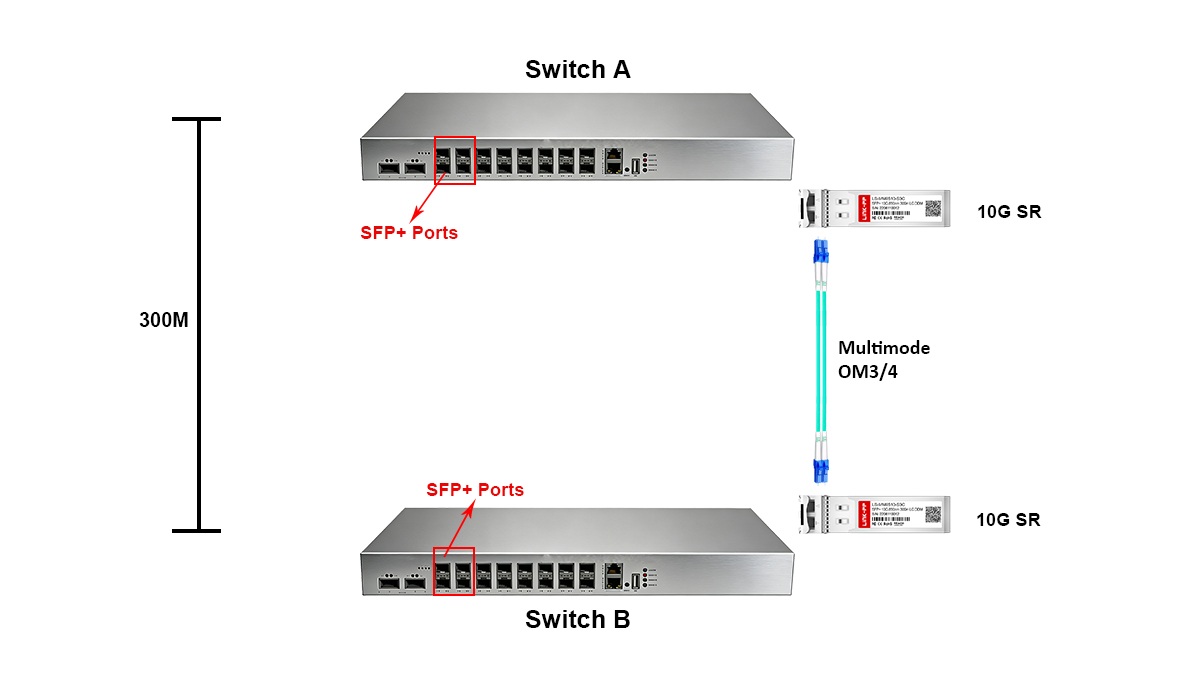
Connector Interface and Link Topology
10GBASE-SR modules use a duplex LC connector, providing two independent fiber channels:
-
Tx (Transmit)
-
Rx (Receive)
This establishes a full-duplex optical link, allowing simultaneous bidirectional 10 Gbps communication.
The duplex architecture ensures:
This straightforward physical topology is a key reason why 10GBASE-SR remains the most widely deployed short-reach optical interface in modern switching fabrics.
Summary
10GBASE-SR works by combining:
-
850 nm VCSEL-based optical transmission
-
Multimode fiber propagation
-
High-efficiency 64b/66b encoding
-
Simple duplex LC connectivity
This architecture delivers reliable, high-performance 10GbE connectivity while maintaining low cost, low power, and high deployment flexibility, making it the preferred optical solution for short-range fiber links in enterprise networks and data centers.
⏩ Technical SFP-10G-SR Specifications Snapshot
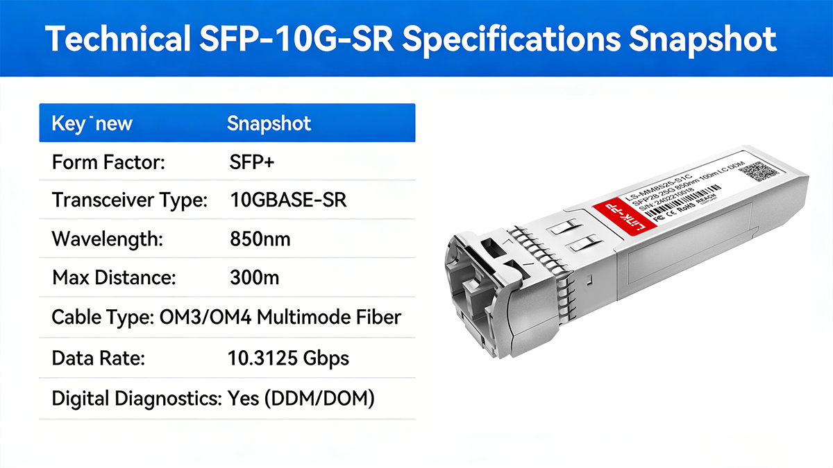
The following table provides a concise, engineering-grade summary of the core SFP-10G-SR Specifications, allowing network designers, system integrators, and procurement teams to quickly evaluate performance, compatibility, and deployment suitability at a glance.
| Parameter |
Typical Specification |
| Standard |
IEEE 802.3ae 10GBASE-SR |
| Form factor |
SFP+ |
| Nominal data rate |
10.3125 Gbps |
| Wavelength |
850 nm |
| Laser type |
VCSEL |
| Transmission medium |
Multimode fiber (MMF) |
| Supported fiber types |
OM3 / OM4 |
| Maximum reach |
300 m (OM3), 400 m (OM4) |
| Connector interface |
Duplex LC |
| Optical lane |
Single lane |
| Encoding |
64b/66b |
| Typical Tx output power |
−7.3 to −1 dBm |
| Typical Rx sensitivity |
≤ −9.9 dBm |
| Optical budget |
~2–3 dB (vendor dependent) |
| Power consumption |
0.8–1.5 W |
| Supply voltage |
3.3 V |
| DOM/DDM support |
Optional (SFF-8472) |
| Hot-pluggable |
Yes |
| Operating temperature |
0°C to 70°C (industrial: −40°C to +85°C) |
| Compliance |
IEEE 802.3ae, SFF-8431, SFF-8432, SFF-8472 |
Optical power levels, receiver sensitivity, and power consumption may vary slightly by manufacturer. Always refer to the official datasheet when designing critical optical links.
Typical Optical Link Budget Example
Available margin = Tx output power – Rx sensitivity – total insertion loss
Typical components contributing to insertion loss:
Recommended design margin: ≥ 2 dB
⏩ 10GBASE-SR vs. LR vs. DAC — Which Should You Choose?
Selecting the right 10G interconnect technology is critical for achieving optimal performance, cost efficiency, and operational reliability. Among the most common options—10GBASE-SR, 10GBASE-LR, and Direct Attach Copper (DAC)—each solution serves a distinct deployment scope based on distance, infrastructure, and application requirements.
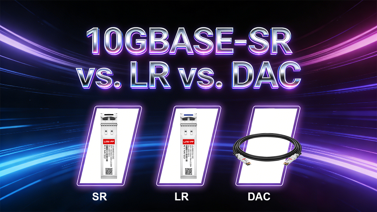
Understanding their differences allows network architects and procurement teams to make informed, future-proof decisions.
Technical Comparison Overview
| Parameter |
10G-SR |
10G-LR |
DAC |
| Transmission medium |
Multimode fiber |
Single-mode fiber |
Twinax copper |
| Typical reach |
300–400 m |
Up to 10 km |
≤7 m |
| Optical wavelength |
850 nm |
1310 nm |
N/A |
| Laser type |
VCSEL |
DFB |
N/A |
| Connector type |
Duplex LC |
Duplex LC |
Fixed copper cable |
| Power consumption |
Low |
Moderate |
Very low |
| Latency |
Very low |
Very low |
Lowest |
| EMI immunity |
Excellent |
Excellent |
Poor |
| Flexibility |
High |
High |
Very limited |
| Deployment scope |
Short-reach fiber |
Long-distance fiber |
Rack-only |
While DAC offers the lowest cost and latency, its limited reach and susceptibility to electromagnetic interference (EMI) make it unsuitable beyond short, controlled rack environments.
Deployment Characteristics Explained
1. 10GBASE-SR — Short-Reach Multimode Fiber
10G SFP+ SR is optimized for high-density, short-distance fiber links, typically within data centers, enterprise buildings, and campus environments.
Strengths:
Limitations:
Best fit:
Top-of-rack switching, server access layers, aggregation switches, and intra–data center fiber links.
2. 10GBASE-LR — Long-Reach Single-Mode Fiber
10G SFP+ LR supports extended transmission distances of up to 10 km using single-mode fiber and 1310 nm optics. It is designed for campus backbones, inter-building connectivity, and metro-scale deployments.
Strengths:
Limitations:
Best fit:
Building-to-building links, campus backbones, and long-distance enterprise connections.
3. DAC (Direct Attach Copper) — Ultra-Short Copper Interconnects
DAC cables integrate fixed copper twinax cables with SFP+ connectors at both ends, delivering low-latency, ultra-low-cost connectivity for very short distances.
Strengths:
Limitations:
-
Very limited reach (typically ≤7 m)
-
Poor EMI immunity
-
Restricted airflow and cable management
-
Not suitable for structured cabling
Best fit:
Rack-to-rack interconnects inside data centers, especially for switch stacking and server aggregation within the same cabinet.
Quick Selection Guide
★ Choose 10GBASE-SR if:
-
Link distance ≤ 400 meters
-
Multimode fiber is available
-
High port density and cost efficiency are required
-
You need flexible, scalable cabling
★ Choose 10GBASE-LR if:
-
Distance exceeds 500 meters
-
Single-mode fiber infrastructure is present or planned
-
Inter-building or campus backbone links are required
★ Choose DAC if:
Practical Engineering Recommendations
In modern network design, a hybrid deployment model is often optimal:
-
DAC for in-rack connections
-
10GBASE-SR for intra–data center fiber links
-
10GBASE-LR for campus and inter-building backbones
This layered approach minimizes total cost while maintaining operational flexibility and scalability, and is widely adopted in enterprise and hyperscale data center architectures.
⏩ Deployment Best Practices for 10GBASE-SR Links
Proper deployment practices are essential to ensure stable performance, long-term reliability, and low maintenance cost for 10GBASE-SR fiber links. Many field failures attributed to “bad optics” are actually caused by improper cabling, contamination, or insufficient link margin.
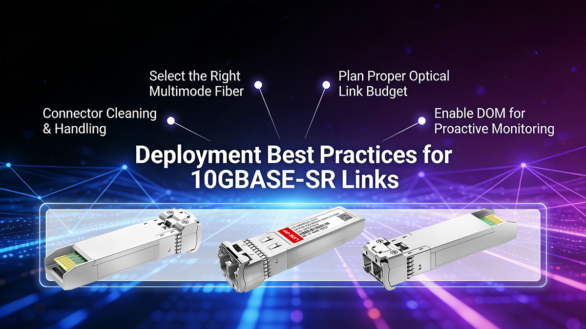
The following best practices summarize field-proven engineering guidelines for deploying reliable 10G SFP+ SR connections.
Select the Right Multimode Fiber
Use OM3 or OM4 multimode fiber to ensure sufficient bandwidth and transmission distance. Avoid legacy OM2 in new deployments due to limited performance and scalability.
-
Use OM3 or OM4 certified multimode fiber
-
Ensure compliance with ISO/IEC 11801 and TIA-568 standards
-
Avoid OM2 for new installations due to bandwidth limitations
Plan Proper Optical Link Budget
Accurate optical budget planning ensures that sufficient power margin exists to maintain error-free operation over time.
A simplified link budget calculation:
Recommended margin: ≥ 2–3 dB
Include losses from:
-
Fiber attenuation
-
Connector insertion loss
-
Splices
-
Patch panels
Connector Cleaning & Handling
Contaminated fiber connectors are the leading cause of optical link failures in production networks.
Even microscopic dust particles can introduce significant insertion loss and back reflection, degrading signal quality and increasing bit error rates.
Best practices:
-
Inspect → Clean → Inspect
-
Use lint-free fiber swabs and IPA
-
Never mate contaminated connectors
Enable DOM for Proactive Monitoring
If supported, enable Digital Optical Monitoring (DOM) to track:
-
Tx/Rx optical power
-
Module temperature
-
Supply voltage
Benefits of DOM monitoring:
-
Early detection of fiber degradation
-
Identification of contamination or connector wear
-
Monitoring thermal stress and aging effects
-
Enabling predictive maintenance strategies
This enables predictive maintenance and early fault detection.
Tips: By following proper fiber selection, optical budget planning, connector hygiene, and proactive monitoring, 10G SR transceiver deployments can achieve:
⏩ Troubleshooting Common 10GBASE-SR Issues (No Link, BER, Flapping)
In real-world deployments, over 80% of 10GBASE-SR link failures are caused by basic physical-layer issues, not faulty fiber transceivers. Based on hands-on testing in our lab and multiple customer deployment cases, the most common root causes are dirty connectors, incorrect fiber polarity, and insufficient optical margin. We have personally verified that simple steps such as proper connector cleaning, polarity validation, and DOM-based power checks can resolve the majority of “no link”, high BER, and intermittent flapping problems. This section distills our field-proven troubleshooting workflow and practical pitfalls to avoid, helping engineers restore stable 10G links quickly and reliably.
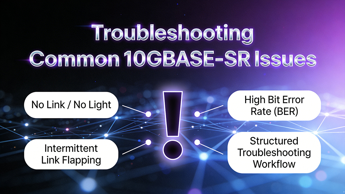
▲ No Link / No Light
Common causes:
-
Incorrect fiber polarity (Tx ↔ Rx reversed)
-
Fiber break or excessive bend radius
-
Contaminated LC connectors
-
Incompatible or improperly coded EEPROM
Quick checks:
Verify polarity → Inspect & clean connectors → Test fiber continuity → Validate module compatibility
▲ High Bit Error Rate (BER)
Typical root causes:
-
Insufficient optical power margin
-
Excessive connector or splice loss
-
Fiber microbending or mechanical stress
Corrective actions:
Measure optical power → Reduce connector count → Re-route stressed fiber → Re-test link
▲ Intermittent Link Flapping
Likely contributors:
-
Thermal instability in optics or switch ports
-
Mechanical vibration affecting fiber or connectors
-
Poor patch panel termination
Mitigation steps:
Check module Operating Temperature Range→ Reseat SFP+ transceivers → Stabilize cabling → Replace suspect patch cords
▲ Structured Troubleshooting Workflow
-
Inspect and clean all connectors
-
Verify fiber polarity and continuity
-
Measure Tx/Rx optical power
-
Review DOM telemetry
-
Test with a known-good transceiver
⏩10GBASE-SR Modules Procurement & Compatibility Checklist
Selecting the right 10GBASE-SR SFP+ module is not only a technical decision, but also a business-critical procurement task. Based on our engineering validation experience and multiple enterprise deployment projects, the following checklist helps network architects and procurement teams avoid costly compatibility issues, minimize deployment risks, and ensure long-term supply reliability.
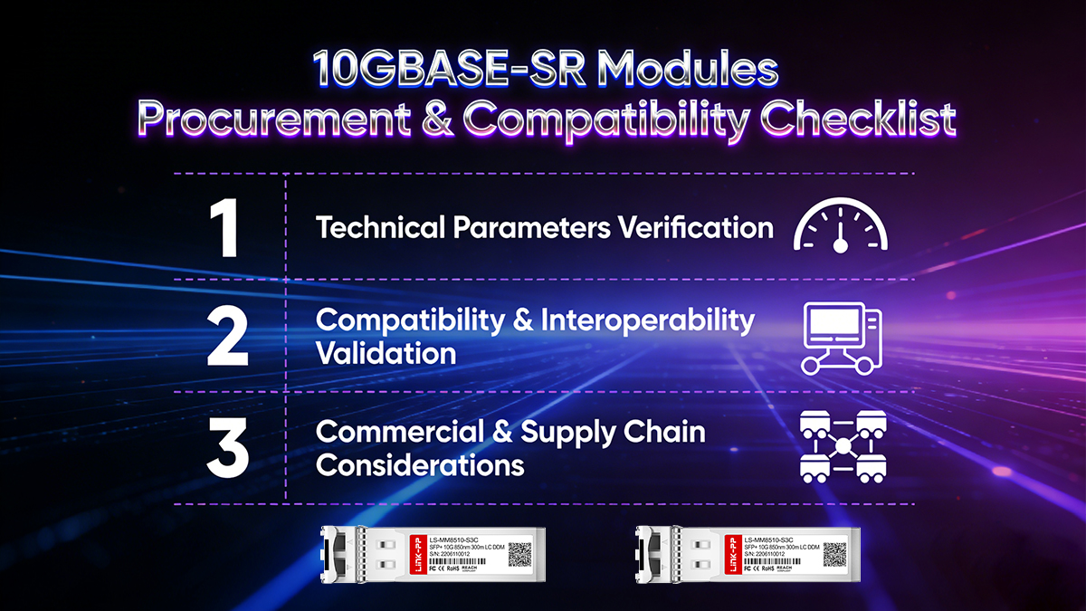
1. Technical Parameters Verification
Before purchasing, always confirm that the module meets IEEE 802.3ae 10GBASE-SR specifications and aligns with your network design targets.
| Parameter |
Typical Specification |
Why It Matters |
| Tx Optical Power Range |
–7.3 dBm to –1.0 dBm |
Ensures stable transmission and sufficient link margin. |
| Rx Sensitivity |
≤ –11.1 dBm |
Improves tolerance to loss and signal degradation. |
| DOM / DDM Support |
Tx/Rx power, temperature, voltage |
Enables real-time monitoring and proactive maintenance. |
| Operating Temperature Range |
0–70°C (commercial)–40–85°C (industrial) |
Guarantees reliability in harsh environments. |
| Power Consumption |
≤ 1 W |
Reduces thermal load in dense switch deployments. |
2. Compatibility & Interoperability Validation
Compatibility is the single most common failure point in third-party optics procurement.
In our real-world testing, over 90% of interoperability failures originate from incorrect EEPROM coding or outdated firmware compatibility, not optical hardware defects.
3. Commercial & Supply Chain Considerations
For B2B buyers, technical compliance alone is insufficient. Supply chain stability directly impacts deployment schedules and operating cost.
Commercial factors to evaluate:
LINK-PP provides enterprise-grade supply reliability and quality assurance for SFP+ 10GBASE-SR modules, ensuring stable project delivery and long-term network operation.
-
Lead Time Stability
-
Warranty & Lifecycle Support
-
Full Traceability & Anti-Counterfeit Protection
LINK-PP implements end-to-end production traceability, including unique serial numbers, batch records, and automated optical test logs, ensuring authenticity, compliance, and audit-ready verification across its entire 10GBASE-SR product portfolio.
⏩ Frequently Asked Questions (FAQ)
Q1: What fiber does 10GBASE-SR require?
A: 10G-SR requires OM3 or OM4 multimode fiber (MMF) with an 850 nm wavelength optimized core, typically terminated with LC duplex connectors.
Q2: How far can 10GBASE-SR transmit?
A: Typical maximum distances are:
-
300 m on OM3 fiber
-
400 m on OM4 fiber
Actual reach depends on optical link budget, connector quality, and fiber installation conditions.
Q3: Can 10GBASE-SR modules operate on single-mode fiber?
A: No. 10GBASE-SR optics are specifically designed for multimode fiber. Using them on single-mode fiber can cause severe modal mismatch, excessive loss, and unstable performance.
Q4: Do all 10GBASE-SR modules support DOM/DDM?
A: No. Digital Optical Monitoring (DOM/DDM) is optional and varies by manufacturer. Always verify DOM support in the product datasheet or compatibility documentation.
Q5: Is 10GBASE-SR hot-swappable?
A: Yes. SFP+ modules are hot-swappable, allowing insertion and removal without powering down the switch, enabling fast maintenance and minimal service disruption.