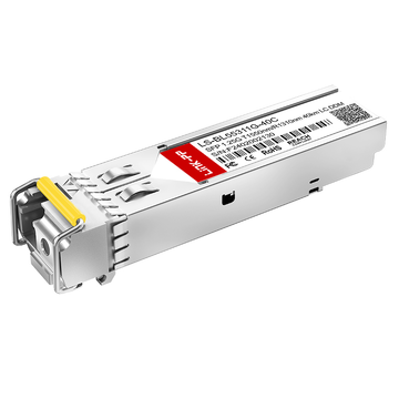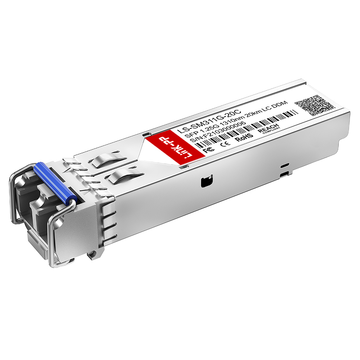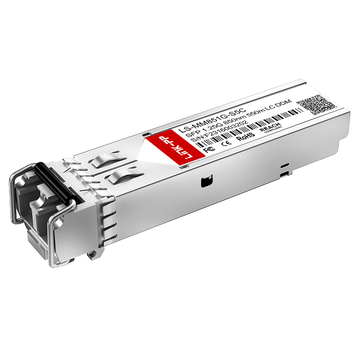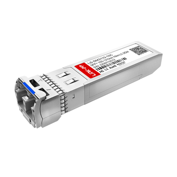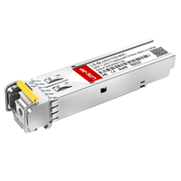
Fiber SFPs (Small Form-factor Pluggable transceivers) are compact, standardized optical modules that enable network devices—such as switches, routers, and servers—to transmit data over fiber optic links with high flexibility, scalability, and reliability. By converting electrical signals into optical signals and vice versa, SFP Transceiver serve as the critical interface between networking hardware and optical cabling infrastructure.
Unlike fixed optical ports, SFP-based architectures allow network designers to adapt link speed, transmission distance, and fiber type simply by changing the transceiver module, without replacing the underlying hardware platform. This modular approach significantly reduces upgrade costs, shortens deployment cycles, and simplifies long-term network expansion.
Today, Fiber SFPs play a central role across a wide range of network environments—from enterprise campus backbones and hyperscale data centers to metro aggregation networks and long-haul telecom systems. With speed options ranging from 1G and 10G to 25G and beyond, and with support for both multimode and single-mode fiber, Fiber SFP Modules provide a highly versatile foundation for modern optical networking.
By reading this guide, you will learn:
-
What Fiber SFPs are and how they work, including the fundamentals of optical transmission and module design
-
The key Fiber SFP types, speed classes, and fiber options, and how they impact network performance and scalability
-
How to select the right Fiber SFP for data center, enterprise, and telecom use cases based on technical and operational requirements
-
The most important compatibility, performance, installation, and procurement considerations for reliable deployment
This practical, engineer-focused guide is designed to help IT professionals, network architects, and enterprise buyers make informed decisions when designing, upgrading, or maintaining fiber-based network infrastructures.
🏆Overview: What Are Fiber SFPs?
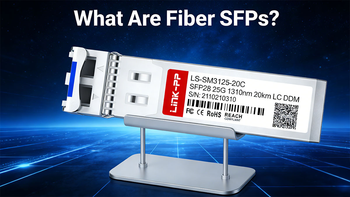
Fiber SFPs (Small Form-factor Pluggable transceivers) are compact, standardized optical modules used to interface network devices—such as switches, routers, and servers—with fiber optic cabling. Acting as media conversion and signal transmission interfaces, SFP Fiber Modules convert electrical signals into optical signals for transmission across fiber, and then convert them back at the receiving end.
Unlike fixed optical ports, SFP-based interfaces allow modular network design. A single switch port can support different transmission distances, fiber types, and data rates simply by changing the SFP module. This flexibility makes SFP Fiber Transceiver a foundational component in scalable and future-ready network architectures.
Core Characteristics of Fiber SFPs
1. Hot-Swappable Form Factor
SFPs are hot-pluggable, meaning they can be inserted or removed while the system is powered on. This capability minimizes downtime during network upgrades, maintenance, and fault replacement, making them especially valuable in data centers and carrier-grade environments where uptime is mission-critical.
2. Standardized Mechanical and Electrical Interface (MSA)
Most Fiber SFPs follow Multi-Source Agreement (MSA) specifications, ensuring mechanical compatibility and electrical interoperability across different vendors’ networking equipment. This open standard allows network operators to deploy third-party modules without being locked into a single hardware ecosystem.
3. Optical Signal Transmission
Fiber SFP Modules use laser diodes or LEDs to transmit data over fiber at specific wavelengths, commonly:
-
850 nm for short-reach multimode fiber (MMF),
-
1310 nm for medium-distance single-mode fiber (SMF),
-
1550 nm for long-haul single-mode transmission.
These wavelengths are selected to optimize transmission distance, attenuation, and signal integrity.
🏆Key Types of Fiber SFPs (SX, LX, ZX, BiDi, CWDM/DWDM)
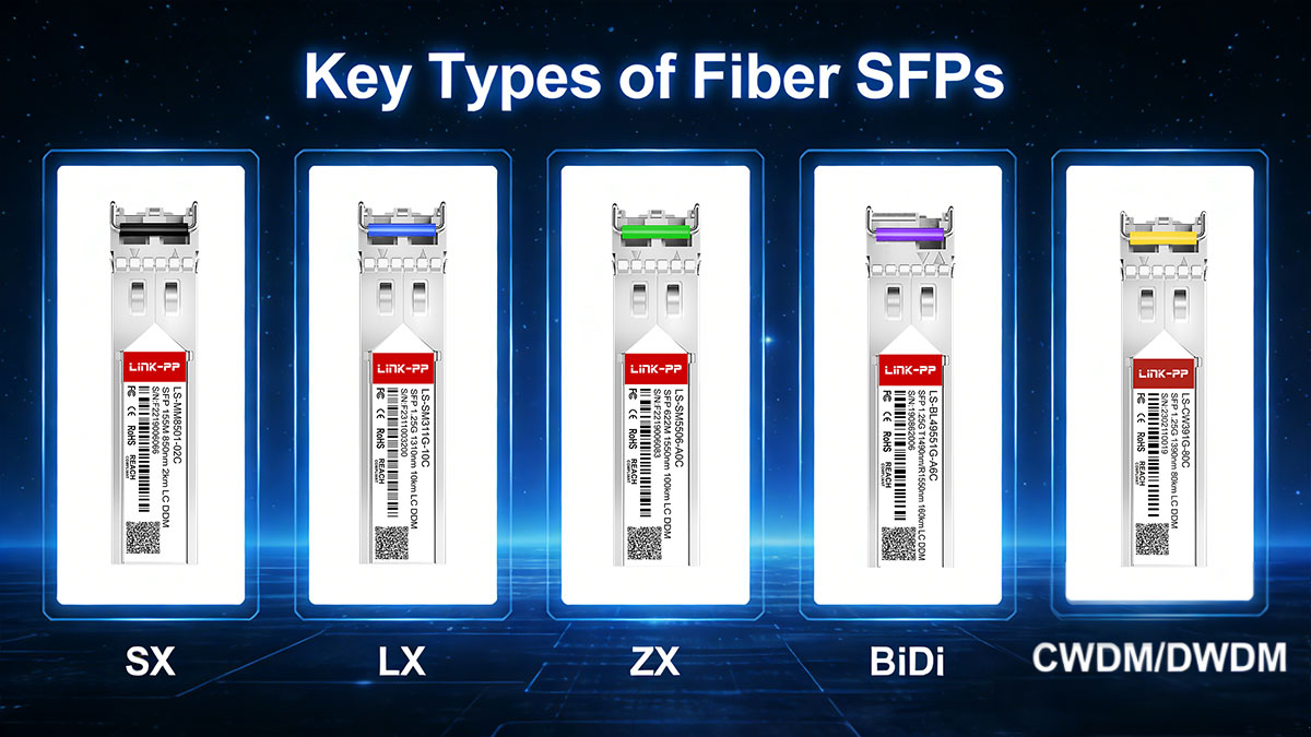
Fiber SFP naming conventions are designed to encode transmission distance, supported fiber type, and operating wavelength, allowing network engineers to quickly identify the most suitable transceiver for a given deployment scenario. These standardized naming rules significantly reduce configuration errors and improve deployment efficiency across enterprise, data center, and telecom environments.
In practice, Fiber SFPs are primarily classified by transmission reach, fiber mode, and optical technology.
Classification by Transmission Distance
SX – Short Reach (Multimode Fiber)
-
Fiber: Multimode (OM2 / OM3 / OM4)
-
Wavelength: 850 nm
-
Typical Distance: Up to 550 meters (depending on fiber grade)
1000Base-SX SFP transceivers are optimized for short-distance, high-bandwidth transmission over multimode fiber. They are most commonly deployed in:
-
High-density data centers
-
Enterprise access and aggregation layers
-
Server-to-switch and switch-to-switch interconnects
Thanks to the relatively low cost of multimode optics and cabling, SX modules provide an economical solution for intra-rack and inter-row connectivity, especially in environments with high port density.
LX – Long Reach (Single-Mode Fiber)
-
Fiber: Single-mode (OS2)
-
Wavelength: 1310 nm
-
Typical Distance: Up to 10 km
LG-LX modules enable medium-range optical transmission over single-mode fiber and are widely used for:
-
Campus backbone links
-
Building-to-building interconnects
-
Metro access networks
Their extended reach and lower signal attenuation make LX SFPs ideal for environments where network nodes are distributed across large geographic areas.
EX / ZX – Extended Reach
-
Fiber: Single-mode (OS2)
-
Wavelength: 1310 nm or 1550 nm
-
Typical Distance: 40 km – 80 km
SFP-EX and SFP-ZX Fiber Modules are engineered for long-distance optical transmission, primarily serving:
-
Metro aggregation networks
-
Telecom access and backhaul links
-
Industrial and utility communication systems
Operating at longer wavelengths—particularly 1550 nm—these modules achieve lower fiber attenuation, enabling significantly extended transmission distances.
EZX / ZR – Ultra Long Reach
-
Fiber: Single-mode (OS2)
-
Wavelength: 1550 nm
-
Typical Distance: 100 km – 160 km+
SFP-EZX and SFP-ZR modules are designed for ultra-long-haul transmission, supporting mission-critical applications such as:
-
Telecom backbone networks
-
Long-distance carrier interconnects
-
High-capacity metro-core links
These modules typically require high-output lasers, advanced receiver sensitivity, and precise optical power control, and are often deployed alongside optical amplifiers and dispersion compensation systems.
BiDi (Bidirectional) Fiber SFPs
Bidirectional BiDi SFPs transmit and receive data over a single fiber strand by using two different wavelengths, enabling full-duplex communication on one optical core. This is achieved through integrated wavelength-division multiplexing (WDM) filters inside the transceiver.
Key Characteristics of BiDi SFPs:
-
Uses paired wavelengths such as 1310 nm / 1550 nm or 1270 nm / 1330 nm
-
Requires matched transceiver pairs installed at opposite ends of the link
-
Reduces fiber usage by 50% compared to traditional duplex fiber links
Typical Applications:
-
Fiber-constrained environments
-
FTTx access networks
-
Metro aggregation systems
-
Industrial and surveillance networks
BiDi SFP Modules significantly lower cabling costs and simplify fiber management, making them a strategic choice where fiber resources are limited or expensive.
CWDM and DWDM SFP Fiber Modules
For large-scale optical transport systems, wavelength-division multiplexing (WDM) technologies allow multiple data channels to be transmitted simultaneously over a single fiber strand, dramatically increasing network capacity.
CWDM (Coarse Wavelength Division Multiplexing)
-
Channel count: 8–18 wavelengths
-
Channel spacing: 20 nm
-
Typical Distance: Up to 80 km
-
Applications: Metro networks, enterprise inter-campus links
CWDM SFPs provide a cost-effective solution for increasing fiber utilization without the complexity and expense of dense optical systems.
DWDM (Dense Wavelength Division Multiplexing)
-
Channel count: 40–96+ wavelengths
-
Channel spacing: 100 GHz / 50 GHz
-
Typical Distance: 100 km – 1000+ km (with amplification)
-
Applications: Carrier backbone, national and international telecom networks
DWDM SFP form the backbone of high-capacity optical transport networks, enabling massive bandwidth scaling while minimizing fiber infrastructure requirements.
How to Choose the Right Fiber SFP Type
| Network Scenario | Recommended SFP Type |
|---|---|
| Data center short links | SX (MMF, 850 nm) |
| Campus backbone | LX (SMF, 1310 nm) |
| Metro access | EX / ZX |
| Long-haul backbone | ZR / DWDM |
| Fiber-limited deployments | BiDi |
🏆Speed Classes — SFP vs. SFP+ vs. SFP28 (1G–25G)
Fiber SFPs are also classified by data transmission rate, which directly impacts network architecture, scalability, power efficiency, and future upgrade paths. For IT architects and enterprise buyers, selecting the right speed class is not only about bandwidth — it is about long-term infrastructure strategy, port density, operational cost, and 2026 data center trends.
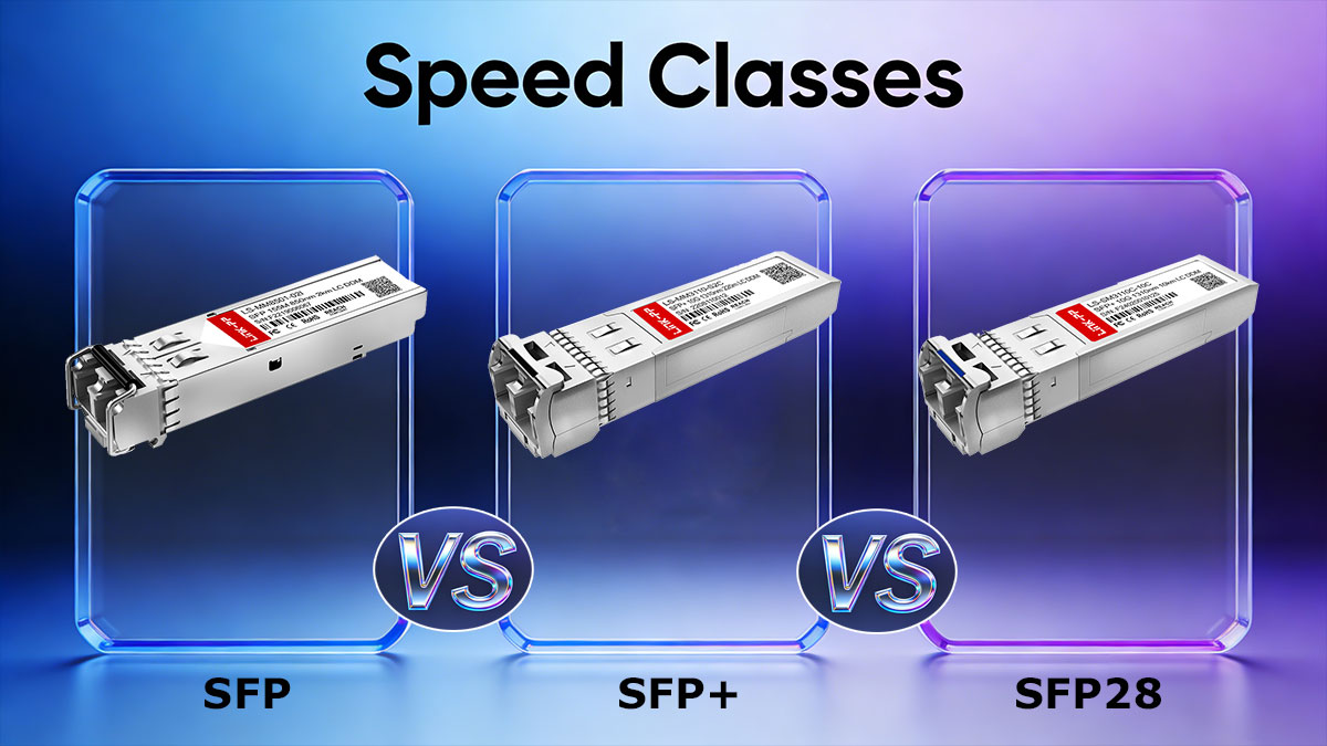
Below is a practical comparison and selection logic for 1G, 10G, and 25G SFP Modules, followed by architecture guidance and forward-looking recommendations.
1G SFP — Cost-Efficient Access Connectivity
-
Maximum speed: 1.25 Gbps
-
Common protocols: Gigabit Ethernet (1000BASE-SX / LX), 1G Fibre Channel
-
Typical reach:
-
MMF (SX): up to 550 m
-
SMF (LX): up to 10 km
-
-
Primary use cases:
-
Enterprise access networks
-
Campus distribution layers
-
Industrial and legacy IT systems
-
Why choose 1G SFP?
1G SFP modules remain widely deployed due to their low cost, broad compatibility, and proven reliability. They are ideal for:
-
Edge access ports
-
Office LAN switching
-
Surveillance and industrial Ethernet
-
Cost-sensitive campus networks
Limitations:
As application traffic grows (cloud workloads, collaboration tools, AI inference, and IoT), 1G increasingly becomes a performance bottleneck, especially in aggregation layers.
Recommended role in modern networks:
Edge access only — not suitable for core or aggregation layers in new deployments.
10G SFP+ — Enterprise & Data Center Backbone Standard
-
Maximum speed: 10.3125 Gbps
-
Protocols: 10G Ethernet, 10G Fibre Channel
-
Typical reach:
-
SR (850 nm): up to 300–400 m
-
LR (1310 nm): up to 10 km
-
-
Primary use cases:
-
Data center aggregation
-
Enterprise backbone
-
Server uplinks
-
Storage networks
-
Why choose 10G SFP+?
SFP+ offers a 10× bandwidth increase over 1G while maintaining the same compact form factor, making it the most widely deployed optical interface for:
-
Spine–leaf architectures in mid-scale data centers
-
Enterprise core switching
-
Storage and virtualization clusters
Key advantages:
-
Excellent price-to-performance ratio
-
Broad switch and NIC compatibility
-
Mature ecosystem and supply chain
-
Proven reliability for mission-critical networks
Recommended role in modern networks:
Enterprise backbone + mainstream data center aggregation layer.
25G SFP28 — High-Density & Future-Oriented Data Centers
-
Maximum speed: 25.78 Gbps
-
Protocols: 25G Ethernet
-
Typical reach:
-
SR: up to 100 m
-
LR: up to 10 km
-
-
Primary use cases:
-
High-performance data centers
-
5G fronthaul & midhaul
-
AI & HPC clusters
-
Why choose 25G SFP28?
SFP28 enables 2.5× higher throughput than 10G with similar power consumption per port, delivering significant improvements in port density, power efficiency, and cabling simplicity.
Compared with 4×10G designs, 25G provides:
-
Higher bandwidth per switch ASIC lane
-
Lower cost per transmitted bit
-
Simplified cabling and topology
-
Reduced switch count and power footprint
Recommended role in modern networks:
Next-generation data center leaf layer + 5G fronthaul + AI/ML clusters.
Practical Selection Logic: SFP vs. SFP+ vs. SFP28
| Network Layer | Recommended Speed | Rationale |
|---|---|---|
| Access Layer (End devices, IoT, offices) | 1G SFP | Cost efficiency, wide compatibility |
| Enterprise Core / Aggregation | 10G SFP+ | Balanced bandwidth and cost |
| Data Center Leaf / Spine | 25G SFP28 | High density, low power, scalable |
| 5G Fronthaul / Cloud Edge | 25G SFP28 | High throughput, low latency |
Quick Decision Rules:
-
Choose 1G when budget and compatibility dominate.
-
Choose 10G when performance and stability are required.
-
Choose 25G when scalability, power efficiency, and long-term ROI matter most.
Network Architecture Guidance
Enterprise Networks
-
Access: 1G Fiber SFPs
-
Trend: Gradual migration from 1G uplinks → 10G uplinks
Architecture Strategy:
1G → 10G hierarchical model remains cost-effective and operationally simple.
Modern Data Centers (Leaf–Spine)
-
Server Access: 25G SFP28
-
Spine Links: 100G (via 4×25G breakout or QSFP28)
-
Storage Fabric: 25G increasingly replacing 10G
Architecture Strategy:
25G at the edge enables simplified cabling and seamless scaling to 100G and 400G cores.
Telecom & 5G Fronthaul
-
DU–RU Links: 25G SFP28
-
Aggregation: 100G / 400G
-
Reason: High throughput + deterministic latency
2026 Data Center Trends: Why 25G Is Becoming the New Baseline
By 2026, hyperscale and enterprise data centers are rapidly shifting toward 25G-per-lane architectures due to:
-
AI and ML workloads driving massive east–west traffic
-
Cloud-native applications increasing server-to-server communication
-
Power efficiency mandates limiting total rack energy consumption
-
Simplified cabling strategies using fewer, higher-speed links
Key Trend Summary:
-
10G → legacy baseline
-
25G → new mainstream access speed
-
100G / 400G → core & spine layers
This transition makes SFP28 Fiber SFPs the strategic choice for future-proof data center deployments, balancing cost, density, and scalability.
Practical Recommendation
For organizations planning new infrastructure or major upgrades in 2026 and beyond, a 25G-first design strategy delivers:
-
Lower long-term TCO
-
Higher network utilization
-
Improved power and cooling efficiency
-
Seamless migration toward 100G / 400G cores
When selecting Fiber SFP modules, enterprise buyers increasingly prioritize MSA compliance, interoperability, optical performance stability, and vendor reliability — areas where LINK-PP Fiber SFPs are engineered to support enterprise-grade and carrier-grade deployments.
🏆Fiber Types & Connectors — MMF vs. SMF, OM3/OM4, OS2, LC/SC/MTP
Selecting the correct fiber type and connector interface is essential for achieving optimal transmission distance, signal quality, port density, and long-term network scalability. In Fiber SFP deployments, these choices directly affect optical loss, power budget, upgrade flexibility, and operational reliability.
1. Multimode vs. Single-Mode Fiber — When to Use Each
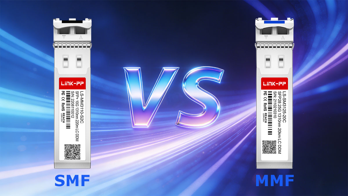
Multimode Fiber (MMF)
-
Core diameter: 50 µm (OM2 / OM3 / OM4 / OM5)
-
Typical wavelength: 850 nm
-
Distance: up to 100–550 m
-
Best for: High-density, short-reach links inside data centers
OM3 and OM4 are the most widely deployed MMF standards, supporting 10G and 25G short-reach interconnects in modern data centers.
Single-Mode Fiber (SMF)
-
Core diameter: ~9 µm
-
Standard: OS2
-
Typical wavelengths: 1310 nm / 1550 nm
-
Distance: 10 km to 160+ km
-
Best for: Campus backbone, metro access, and telecom networks
Engineering rule of thumb:
Use MMF SFP for short-distance, high-density data center links, and SMF SFP for long-distance, scalable enterprise and telecom networks.
2. Fiber Standards Explained — OM3 / OM4 vs OS2
-
OM3 / OM4 (MMF):
Optimized for short-reach high-speed transmission, commonly used for 10G and 25G data center interconnects. OM4 offers extended reach and better bandwidth performance than OM3. -
OS2 (SMF):
Designed for long-distance transmission and future-proof scalability, making it the default fiber standard for campus, metro, and telecom infrastructure.
Selection guidance:
Choose OM3/OM4 for rack-to-rack and row-level connections, and OS2 for backbone and inter-building links.
3. Connector Types — LC vs SC vs MTP/MPO
-
LC Connector:
The industry-standard interface for Fiber SFPs, offering high port density, low insertion loss, and excellent mechanical reliability. -
SC Connector:
Larger form factor, mainly used in legacy enterprise and telecom networks. -
MTP / MPO:
Multi-fiber connectors used for 40G / 100G / 400G high-density trunk cabling, especially in modern hyperscale data centers.
Best practice:
Use LC connectors for SFP-based links and MTP/MPO for high-speed backbone architectures to optimize density and cable management.
🏆How Fiber SFPs Work — Transmitters, Receivers, Wavelengths & Optics Basics
Fiber SFPs function as electro-optical conversion interfaces, enabling high-speed data transmission over optical fiber by converting electrical signals into modulated light and vice versa. Each module integrates precision optical components and digital control circuits to ensure stable, low-error communication across varying distances.
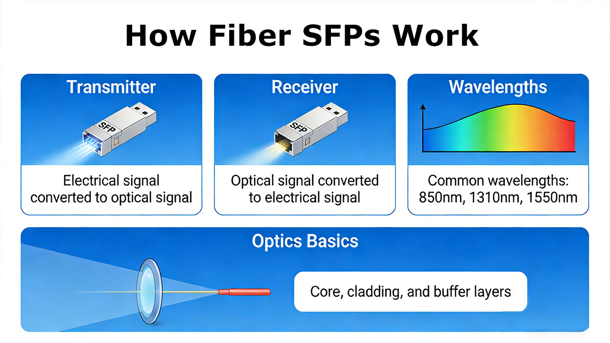
Core Optical Architecture — TX & RX Explained
A Fiber SFP integrates two main optical subassemblies:
-
Transmitter (TX): Converts electrical data into modulated light using laser diodes (VCSEL for 850 nm MMF, DFB/FP lasers for 1310 nm and 1550 nm SMF).
-
Receiver (RX): Converts incoming optical signals back into electrical form using high-sensitivity photodiodes (PIN or APD).
This bidirectional optical conversion enables full-duplex transmission, allowing simultaneous send and receive operations on separate fiber strands (or different wavelengths in BiDi designs).
Wavelengths & Optical Transmission Principles
Fiber SFPs operate at standardized wavelengths to optimize fiber performance and minimize signal attenuation:
-
850 nm: Multimode short-reach links (SX)
-
1310 nm: Single-mode long-reach links (LX, EX)
-
1550 nm: Extended and ultra-long reach (ZX, ZR, DWDM)
Longer wavelengths exhibit lower attenuation in single-mode fiber, enabling transmission distances from 10 km up to 160+ km, particularly when combined with optical amplification and DWDM technology.
Optical Power Budget & Key Performance Parameters
The optical power budget—defined as:
TX output power − RX sensitivity
determines the maximum achievable transmission distance under defined fiber loss and connector conditions.
Key optical parameters include:
-
Output optical power: Determines launch strength
-
Receiver sensitivity: Minimum detectable signal level
-
Extinction ratio: Signal clarity between logical “1” and “0”
-
Return loss: Reflection tolerance affecting link stability
Together, these parameters directly influence bit error rate (BER), link margin, and long-term system reliability, making them essential benchmarks when evaluating enterprise- and carrier-grade Fiber SFPs.
🏆Hot-Swappable Design, DOM & MSA Compliance
Modern Fiber SFPs are designed around hot-swappable architecture, real-time optical monitoring, and standardized interoperability, enabling flexible deployment, simplified maintenance, and multi-vendor network compatibility.
These three engineering principles significantly improve network uptime, operational efficiency, and long-term scalability.
Hot-Swappable Design — Zero-Downtime Maintenance
Fiber SFP Modules support hot-swapping, allowing modules to be inserted or removed without powering down network equipment.
Operational advantages:
-
Enables rapid replacement of failed transceivers
-
Minimizes service disruption and maintenance windows
-
Supports live network upgrades and capacity expansion
This capability is essential for mission-critical environments such as data centers, financial networks, and telecom infrastructure, where downtime directly translates into business risk.
Digital Optical Monitoring (DOM) — Real-Time Performance Visibility
Most modern SFP Transceivers integrate Digital Optical Monitoring (DOM), also referred to as DDM, which provides continuous visibility into optical and electrical parameters.
Key monitored metrics include:
-
Transmit optical power (TX)
-
Receive optical power (RX)
-
Module temperature
-
Supply voltage
-
Laser bias current
Operational value:
-
Enables predictive maintenance
-
Simplifies troubleshooting and root-cause analysis
-
Helps detect fiber degradation, contamination, or connector loss
DOM significantly improves network observability and reliability, especially in large-scale deployments.
MSA Compliance — Ensuring Interoperability & Vendor Flexibility
Fiber SFPs are governed by Multi-Source Agreement (MSA) standards, which define mechanical, electrical, and optical specifications to ensure cross-vendor compatibility.

Key benefits of MSA-compliant design:
-
Seamless interoperability across switch and router platforms
-
Avoids vendor lock-in
-
Enables flexible sourcing and supply-chain resilience
High-quality, MSA-compliant SFP Fiber Transceivers— such as LINK-PP Fiber SFPs — provide enterprise and carrier networks with consistent performance, predictable interoperability, and long-term procurement stability.
🏆Fiber SFPs Compatibility & Interoperability
Although Fiber Transceivers follow MSA standards, real-world deployments often encounter vendor-specific compatibility constraints, especially due to proprietary firmware checks and EEPROM coding. Understanding interoperability principles is essential to ensure stable network operation, smooth deployment, and procurement flexibility.
Why Compatibility Issues Still Exist Despite MSA Standards
While MSA defines mechanical, electrical, and optical specifications, some switch and router vendors implement vendor-locked EEPROM authentication mechanisms that restrict the use of third-party modules.
Common compatibility challenges include:
-
Firmware-based transceiver authentication checks
-
Vendor-specific EEPROM encoding requirements
-
Platform-level optics qualification policies
As a result, not all MSA-compliant SFPs are automatically accepted across all network platforms.
What Network Teams Should Verify Before Deployment
To minimize operational risk, engineers and procurement teams should validate:
-
Firmware compatibility with target switch OS versions
-
Approved transceiver lists from equipment vendors
-
Third-party interoperability certification reports
-
Field-proven deployment references
This validation process ensures plug-and-play installation, stable link operation, and long-term network reliability.
Role of MSA-Compliant Third-Party Fiber SFPs
High-quality MSA-compliant Third-Party SFP Modules — are widely adopted by enterprise and telecom customers due to:
-
Documented multi-vendor interoperability testing
-
Stable EEPROM coding control
-
Long-term product lifecycle management
-
Consistent optical and electrical performance
This approach enables organizations to avoid vendor lock-in, optimize procurement costs, and maintain deployment flexibility, while preserving carrier-grade network stability.
🏆Fiber SFP Performance, Installation, Monitoring & Procurement
This section consolidates key performance metrics, installation best practices, testing & monitoring, troubleshooting, and procurement guidance for Fiber SFPs, ensuring reliable, high-performance, and cost-effective deployments in data centers, enterprise, and telecom networks.
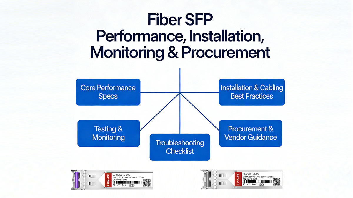
1. Core Performance Specs
-
Bit Error Rate (BER ≤ 10⁻¹²)
-
Optical power budget
-
Receiver sensitivity
-
Operating temperature range
-
Power consumption
These parameters directly impact link reliability, signal integrity, and operational cost, and should be evaluated before deployment.
2. Installation & Cabling Best Practices
-
Clean connectors before insertion
-
Maintain correct fiber polarity
-
Label all fiber paths clearly
-
Control bend radius and cable tension
Proper installation reduces optical loss, BER, and maintenance effort, ensuring long-term network stability.
3. Testing & Monitoring
-
Optical power meters and OTDR for fiber integrity
-
Digital Optical Monitoring (DOM) for real-time module performance
-
Scheduled inspection cycles to detect degradation or faults early
Routine monitoring helps prevent downtime and optimize operational efficiency.
4. Troubleshooting Checklist
-
Common faults: No link light, high BER, optical mismatch, excessive insertion loss
-
Root causes: Connector contamination, fiber damage, module incompatibility
-
Resolution: Clean/replace connectors, repair fiber, swap modules
Structured troubleshooting ensures rapid restoration of network performance.
5. Procurement & Vendor Guidance
-
Evaluate MSA compliance, certifications, optical performance testing, warranty/RMA policies
-
Prefer vendors with stable supply chains and long-term lifecycle support
-
LINK-PP SFP Modules offer reliable third-party interoperability, consistent optical performance, and operational stability for enterprise and telecom deployments
This approach reduces vendor lock-in risk while maintaining predictable network performance.
🏆Fiber SFPs vs. Copper SFPs
When designing network links, understanding the differences between Fiber and Copper SFPs is essential for performance, reliability, and security. Each media type has unique advantages and limitations depending on distance, bandwidth, cost, and environment.
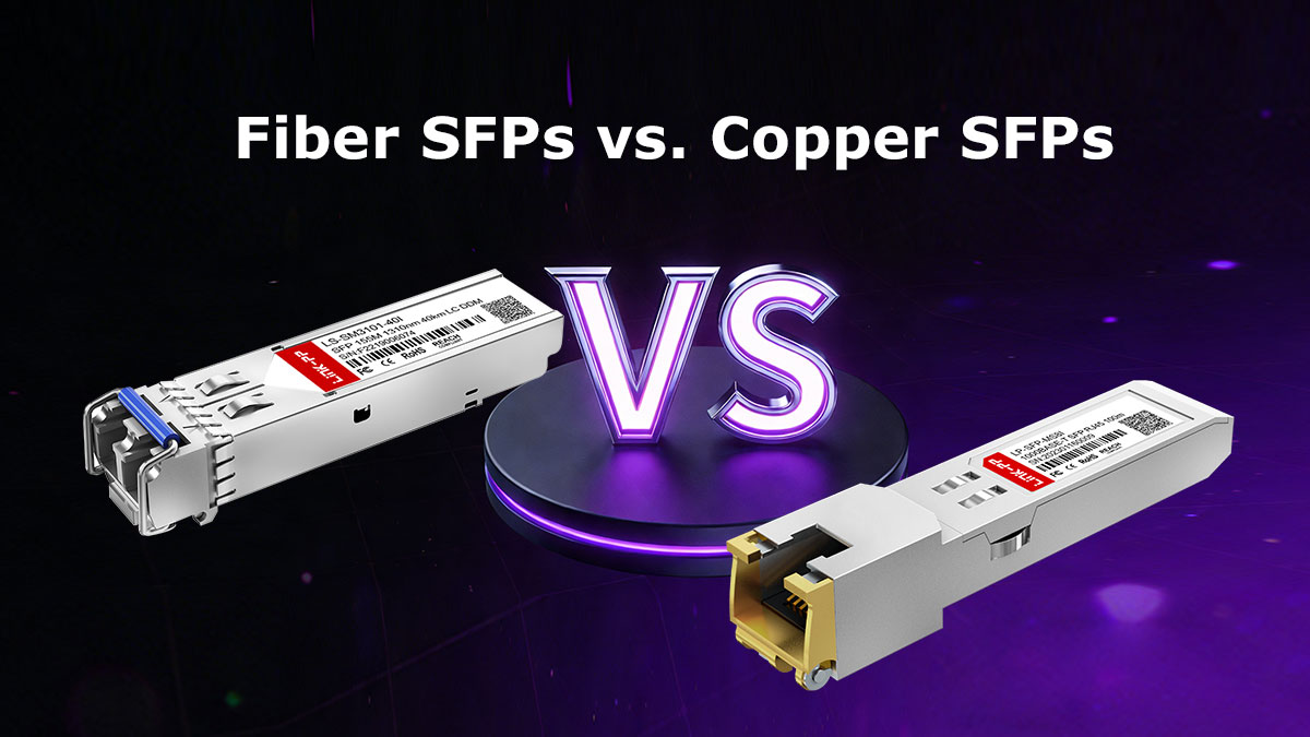
Transmission Distance & Speed
| Feature | Fiber SFP | Copper SFP (RJ45) |
|---|---|---|
| Max Distance | Up to 160+ km (SMF) | ~100 m |
| Typical Speeds | 1G → 25G (SFP → SFP28) | 1G → 10G |
| Use Case | Data center interconnect, campus backbone, metro/telecom | Short-reach access, legacy LAN, patch connections |
Rule of thumb: Use Fiber SFPs for long-distance and high-speed links, Copper SFPs for short, cost-sensitive deployments.
Power, Heat & Operational Considerations
-
Fiber SFP Modules: Lower power consumption (~0.8 W), minimal heat, immune to EMI
-
Copper SFP Modules: Higher power (~1.05 W), generates more heat, susceptible to electromagnetic interference
Fiber optics reduces cooling requirements and interference risks, which is critical in dense racks and high-speed data centers.
Security & Reliability
-
Fiber SFPs: Harder to tap, no electromagnetic emissions, better for sensitive or regulated environments
-
Copper SFPs: Easier to tap, susceptible to EMI and signal degradation over distance
Recommendation: For enterprise, data center, or telecom links where security, reliability, and distance matter, Fiber SFPs — including MSA-compliant options like LINK-PP modules — are preferred.
🏆Conclusion & Practical Next Steps
Fiber SFPs are essential building blocks for scalable, high-performance optical networks. By mastering module types, speed classes, fiber selection, optical performance metrics, installation best practices, and compatibility standards, IT and network teams can design infrastructures that maximize reliability, efficiency, and long-term cost-effectiveness.
Practical next steps for network planners and engineers:
-
Evaluate network requirements — distance, speed, density, and security needs.
-
Select the right Fiber SFP type — SFP, SFP+, SFP28, and corresponding MMF/SMF fibers.
-
Verify interoperability and MSA compliance — consider vendor compatibility and third-party certifications.
-
Plan installation, monitoring, and maintenance — follow best practices for cabling, DOM monitoring, and troubleshooting.
-
Optimize procurement decisions — ensure vendor reliability, warranty support, and supply-chain stability.
For enterprise, data center, or telecom deployments seeking reliable MSA-compliant modules, explore the full range of Fiber SFPs at the LINK-PP Official Store.
Glossary & Quick Reference Chart
| Term | Definition |
|---|---|
| BER (Bit Error Rate) | The number of bit errors per unit of time or data transmitted; indicates signal integrity. |
| DOM (Digital Optical Monitoring / DDM) | Real-time monitoring of optical module parameters such as TX/RX power, temperature, and voltage. |
| EEPROM (Electrically Erasable Programmable Read-Only Memory) | Stores module-specific data, including vendor ID, speed, and compatibility info. |
| WDM (Wavelength Division Multiplexing) | Technology that transmits multiple optical signals simultaneously on different wavelengths over the same fiber. |
| CWDM (Coarse Wavelength Division Multiplexing) | WDM type with widely spaced wavelengths (8–18 channels), suitable for metro networks up to ~80 km. |
| DWDM (Dense Wavelength Division Multiplexing) | WDM type with tightly spaced wavelengths (40–96+ channels), designed for ultra-high-capacity long-haul networks. |
| FTTx (Fiber to the x) | Generic term for fiber-optic broadband deployments (FTTH, FTTB, FTTC), extending fiber to homes, buildings, or curb. |
| OTDR (Optical Time-Domain Reflectometer) | Instrument used to test fiber continuity, loss, and locate faults along fiber links. |
| SFP (Small Form-factor Pluggable) | Compact, hot-swappable optical transceiver used to connect network devices over fiber or copper. |
| SFP+ / SFP28 | Enhanced versions of SFP supporting 10 Gbps and 25 Gbps speeds, respectively. |
| LC / SC / MTP/MPO | Common optical connector types; LC (small form factor), SC (legacy), MTP/MPO (multi-fiber high-density trunk). |
| MMF (Multimode Fiber) | Fiber type with larger core diameter (50–62.5 µm) for short-distance links, typically 850 nm wavelength. |
| SMF (Single-Mode Fiber) | Fiber type with ~9 µm core for long-distance links, typically 1310/1550 nm wavelength. |
| SX / LX / ZX / EX / EZX / BiDi | Fiber SFP naming conventions indicating distance, fiber type, and wavelength (SX: short, LX: long, ZX/EX/EZX: extended/ultra-long, BiDi: bidirectional). |
| MSA (Multi-Source Agreement) | Industry standard defining mechanical, electrical, and optical specs for transceivers to ensure multi-vendor interoperability. |