
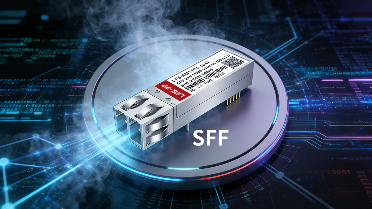
Fiber optic networks rely on optical transceivers to convert electrical signals into optical signals for transmission over fiber cables. Among the early compact solutions developed for this purpose, the SFF transceiver (Small Form Factor transceiver) played an important role in increasing port density and enabling more compact networking equipment.
An SFF transceiver is a board-mounted optical modules designed to provide fiber connectivity for networking and telecommunications systems. Compared with earlier optical modules such as GBIC, SFF modules introduced a smaller footprint, allowing manufacturers to integrate more optical interfaces into switches, routers, and telecom transport equipment. These modules typically support data rates used in Fast Ethernet, Gigabit Ethernet, and SONET/SDH networks.
Although modern optical networking commonly uses hot-pluggable form factors such as SFP and SFP+, SFF transceivers remain relevant in many legacy systems and specialized hardware platforms. Understanding how SFF optical modules work, their technical characteristics, and their typical applications can help network engineers maintain existing infrastructure and better understand the evolution of optical transceiver technologies.
This guide explains what an SFF transceiver is, how it works, the key technical specifications, common types, and where these optical modules are still used in today’s fiber optic networks.
⏳ What Is an SFF Transceiver?
An SFF transceiver (Small Form Factor transceiver) is a compact optical module designed to transmit and receive data over fiber optic cables. It converts electrical signals from networking equipment into optical signals for transmission and converts incoming optical signals back into electrical signals. SFF modules were introduced to provide a smaller alternative to earlier optical interfaces, allowing higher port density in networking and telecommunications hardware.
Unlike later hot pluggable optical modules, SFF transceivers are typically board-mounted components that are integrated directly into network devices such as switches, routers, or telecom transport equipment. This design allows manufacturers to build compact systems with integrated fiber interfaces, although it reduces flexibility for field replacement compared with removable optical modules.
Definition of SFF (Small Form Factor)
SFF stands for Small Form Factor, referring to the compact physical design of the optical module. The term originated from early industry efforts to reduce the size of fiber optic transceiver while maintaining reliable optical performance.
The following table highlights the core characteristics associated with the SFF form factor.
| Characteristic |
Description |
Impact on Networking Equipment |
| Form Factor |
Compact optical module design |
Allows higher port density |
| Installation Type |
Board-mounted |
Integrated into device hardware |
| Typical Data Rates |
100Mbps–1Gbps |
Supports Fast Ethernet and Gigabit Ethernet |
| Fiber Interface |
LC or SC connectors |
Compatible with common fiber links |
These characteristics made SFF modules attractive for equipment vendors that needed smaller optical interfaces without significantly increasing system size.
Basic Structure of an SFF Optical Module
An SFF optical module contains several core components responsible for optical signal transmission and reception. These components work together to perform the optical-electrical conversion required in fiber optic communication.
Typical internal components include:
- Optical transmitter – usually a laser diode such as FP or DFB that generates the optical signal
- Optical receiver – commonly a PIN photodiode that detects incoming optical signals
- Driver and amplifier circuits – electronic components that control signal modulation and amplification
- Optical interface – fiber connector interface such as LC or SC
- Control and monitoring circuitry – supports stable operation and signal integrity
The integration of these components within a compact module enables reliable optical communication while maintaining a small footprint inside networking hardware.
How SFF Transceivers Work
SFF transceivers operate through a bidirectional conversion process between electrical and optical signals.
The process typically includes the following stages:
- Electrical signal input
The network device sends a high-speed electrical data signal to the transceiver.
- Optical signal generation
The laser diode converts the electrical signal into a modulated optical signal.
- Fiber optic transmission
The optical signal travels through a fiber optic cable to a remote device.
- Optical signal detection
The receiving module uses a photodiode to detect the incoming light signal.
- Electrical signal output
The photodiode converts the optical signal back into an electrical signal that the receiving device can process.
This conversion process enables high-speed data transmission across long distances with minimal signal loss, which is one of the main advantages of fiber optic communication systems.
⏳ Key Technical Characteristics of SFF SFP Transceivers
SFF optical transceiver is designed to deliver reliable optical communication in compact networking hardware. Their technical characteristics are defined by factors such as form factor design, supported data rates, optical wavelength options, and transmission distance. These specifications determine where SFF optical modules can be deployed and how they integrate with different fiber optic networks.
Understanding these characteristics helps network engineers evaluate whether an SFF optical module fits the requirements of a specific telecom or enterprise networking environment.
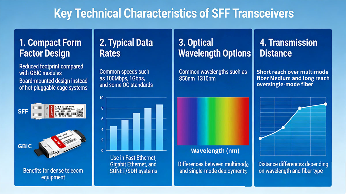
Compact Form Factor Design
One of the defining characteristics of an SFF transceiver is its compact physical structure. The Small Form Factor design was introduced to reduce the space required for optical interfaces while maintaining stable optical performance.
The table below summarizes how the SFF form factor compares with earlier optical module designs.
| Feature |
SFF Transceiver |
Earlier GBIC Transceiver |
| Physical Size |
Smaller footprint |
Larger module size |
| Installation |
Board-mounted |
Pluggable module |
| Port Density |
Higher density possible |
Lower density |
| Integration |
Integrated into hardware |
External removable unit |
This smaller design allowed networking equipment manufacturers to increase port density in switches and telecom transmission systems without significantly expanding device size.
Because SFF modules are mounted directly on the device circuit board, they are typically used in equipment where optical interfaces are intended to remain fixed throughout the product lifecycle.
Typical Data Rates
SFF transceivers support several data rates commonly used in early fiber optic networking standards. These modules were widely deployed in both enterprise and telecommunications environments where moderate bandwidth requirements were sufficient.
Typical supported data rates include:
- 100Mbps for Fast Ethernet applications such as 100BASE-FX transceiver
- 1Gbps for Gigabit Ethernet networks including 1000BASE-SX and 1000BASE-LX
- SONET/SDH speeds such as OC-3 and OC-12 used in telecom infrastructure
These data rates made SFF modules suitable for a wide range of networking applications, from campus backbone connectivity to carrier transport systems.
Although newer optical form factors support significantly higher speeds, the bandwidth capabilities of SFF modules remain adequate for many legacy networks that continue to operate today.
Optical Wavelength Options
SFF optical modules support several wavelengths used in fiber optic communication. The selected wavelength directly affects transmission distance and fiber compatibility.
The most common wavelength options are shown below.
| Wavelength |
Fiber Type |
Typical Use |
| 850nm |
Multimode fiber |
Short-distance links |
| 1310nm |
Single-mode fiber |
Medium-distance transmission |
| 1550nm |
Single-mode fiber |
Long-distance transmission |
Each wavelength operates optimally with specific fiber types. For example, 850nm optics are typically paired with multimode fiber for short-reach connections inside data centers or campus networks, while 1310nm and 1550nm wavelengths are commonly used for longer single-mode fiber links.
Selecting the correct wavelength is therefore an important factor when deploying SFF optical modules in fiber networks.
Transmission Distance
The achievable transmission distance of an SFF transceiver depends on several factors, including wavelength, fiber type, and optical power levels. In general, SFF modules can support a range of distances suitable for enterprise and telecom network deployments.
Typical transmission ranges are summarized below.
| Fiber Type |
Wavelength |
Typical Distance |
| Multimode Fiber |
850nm |
Up to 550m |
| Single-Mode Fiber |
1310nm |
Up to 10km |
| Single-Mode Fiber |
1550nm |
Up to 40km or more |
Short-reach multimode configurations are commonly used for connections within buildings or campuses, while single-mode solutions enable longer distances required for metropolitan or regional networks.
By selecting the appropriate optical specifications, SFF transceivers can support a wide variety of fiber optic network architectures while maintaining reliable signal transmission.
⏳ SFF Transceiver Standards and Interfaces
The design and interoperability of SFF sfp transceivers are defined by a set of industry specifications covering mechanical structure, electrical interfaces, and optical connectivity. These standards allow different manufacturers to produce compatible modules while ensuring that networking equipment can reliably integrate optical communication components.
SFF transceiver standards primarily focus on multi-source agreements, electrical and mechanical specifications, and fiber interface connectors. Together, these elements ensure that SFF optical transceiver module can operate consistently across a variety of telecom and networking platforms.
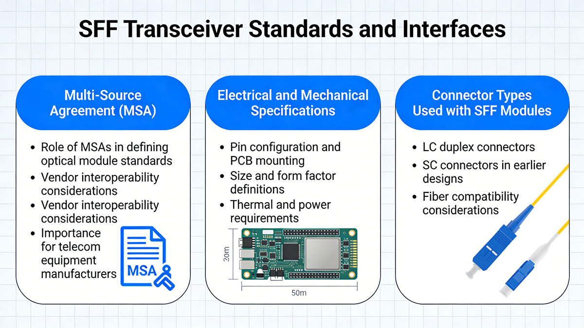
Multi-Source Agreement (MSA)
The SFF transceiver specification is defined through a Multi-Source Agreement (MSA), an industry collaboration that establishes common design guidelines for optical modules. The goal of an MSA is to ensure that optical components from different vendors follow consistent physical and electrical requirements.
The table below outlines the key functions of an MSA in optical module development.
| MSA Function |
Description |
Impact on Optical Modules |
| Mechanical Standardization |
Defines module size and layout |
Ensures hardware compatibility |
| Electrical Interface Definition |
Specifies signal and power interfaces |
Enables reliable system integration |
| Optical Performance Guidelines |
Defines optical parameters |
Supports consistent transmission performance |
| Vendor Interoperability |
Allows multiple manufacturers to produce modules |
Expands ecosystem availability |
Because of these agreements, equipment manufacturers can integrate optical modules into their designs while maintaining flexibility in sourcing components.
MSAs have played an important role throughout the evolution of optical transceiver technology, including later form factors such as SFP and QSFP+.
Electrical and Mechanical Specifications
SFF transceivers follow defined electrical and mechanical parameters to ensure stable operation within networking devices. These specifications describe how the module connects to system hardware and how signals are transmitted between the device and the optical interface.
Key specification areas include:
- Pin configuration – defines how electrical signals and power are delivered to the module
- PCB mounting structure – determines how the module is installed on the device circuit board
- Power consumption limits – ensures compatibility with system power budgets
- Thermal design considerations – supports stable operation under varying temperatures
Because SFF modules are board-mounted rather than hot-pluggable, their electrical connections are integrated directly into the system’s printed circuit board. This design simplifies mechanical construction but reduces the ability to replace modules during operation.
Equipment vendors typically design their hardware around these specifications to ensure consistent optical performance and long-term reliability.
Connector Types Used with SFF Modules
SFF optical modules use standardized fiber connector to link networking equipment with fiber optic cables. The connector type determines how the optical interface physically connects to the fiber infrastructure.
The most commonly used connectors for SFF transceivers are summarized below.
| Connector Type |
Fiber Configuration |
Typical Deployment |
| LC Duplex |
Two-fiber interface |
Gigabit Ethernet links |
| SC |
Two-fiber interface |
Early telecom equipment |
| MT-RJ |
Duplex multimode connector |
Legacy network installations |
Among these options, LC duplex connectors eventually became the most widely adopted because they support compact designs and high port density. SC connectors were commonly used in earlier networking equipment, while MT-RJ connectors appeared in some legacy multimode fiber deployments.
The choice of connector depends on the network design, fiber infrastructure, and hardware compatibility requirements. Selecting the correct connector type ensures proper alignment between the optical module and the fiber optic cable, which is essential for maintaining stable signal transmission.
⏳ Common Types of SFF Transceivers
SFF SFP transceivers were developed to support several networking standards used in enterprise and telecommunications environments. Different module types are designed to match specific data rates, fiber types, and transmission distances. As a result, SFF optical modules can be categorized based on the networking technologies they support.
The most common types include Fast Ethernet SFF modules, Gigabit Ethernet SFF modules, and SONET/SDH SFF modules. Each category serves different network infrastructures and performance requirements.
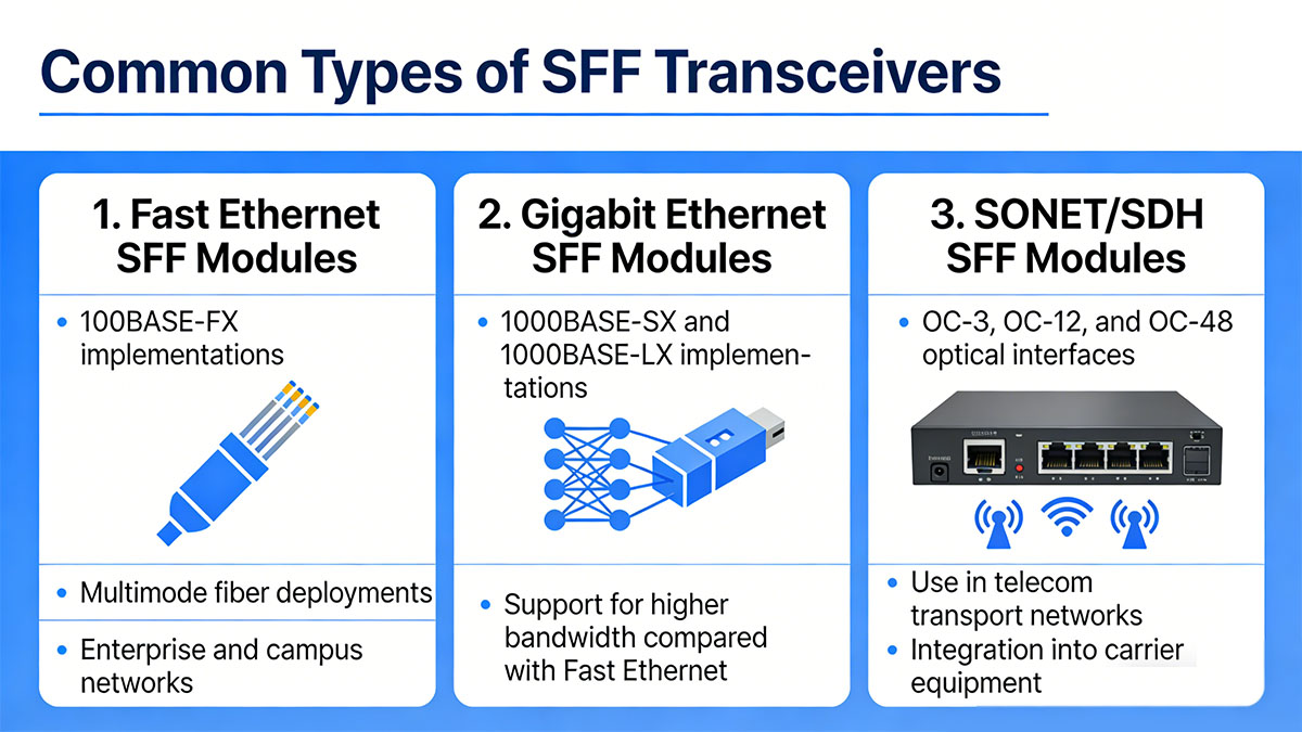
Fast Ethernet SFF Modules
Fast Ethernet SFF transceivers are designed for 100Mbps fiber optic communication, typically used in 100BASE-FX networks. These modules were widely deployed in enterprise networks where fiber connections were required for longer distances than copper Ethernet could support.
Typical characteristics of Fast Ethernet SFF modules are shown below.
| Parameter |
Typical Value |
Description |
| Data Rate |
100Mbps |
Supports Fast Ethernet |
| Wavelength |
1310nm or 850nm |
Depends on fiber type |
| Fiber Type |
Multimode or single-mode |
Determines link distance |
| Transmission Distance |
Up to 2km |
Varies by fiber configuration |
These modules were commonly used in campus networks, industrial Ethernet environments, and early fiber backbone deployments within enterprise infrastructures.
Because Fast Ethernet required relatively modest bandwidth, these SFF modules provided a cost-effective optical solution for extending network connectivity over fiber.
Gigabit Ethernet SFF Modules
Gigabit Ethernet SFF transceivers support 1Gbps data transmission, enabling higher bandwidth fiber links for enterprise backbones and telecommunications infrastructure.
The most common Gigabit Ethernet optical standards used with SFF modules include 1000BASE-SX and 1000BASE-LX.
| Standard |
Wavelength |
Fiber Type |
Typical Distance |
| 1000BASE-SX |
850nm |
Multimode fiber |
Up to 550m |
| 1000BASE-LX |
1310nm |
Single-mode fiber |
Up to 10km |
| 1000BASE-ZX |
1550nm |
Single-mode fiber |
Up to 80km |
These SFP fiber module allowed network operators to deploy higher-speed fiber connections for backbone links, aggregation layers, and inter-building connectivity.
Gigabit Ethernet SFF modules were particularly useful during the transition period when networks were upgrading from Fast Ethernet to Gigabit Ethernet while still using compact integrated optical interfaces.
SONET/SDH SFF Modules
SONET/SDH SFF transceivers are designed for telecommunications transport networks that use synchronous optical standards. These modules are integrated into carrier-grade equipment used for long-distance optical communication.
Common SONET/SDH interfaces supported by SFF modules include the following.
| Optical Standard |
Data Rate |
Typical Use |
| OC-3 / STM-1 |
155Mbps |
Access and aggregation networks |
| OC-12 / STM-4 |
622Mbps |
Metropolitan transport systems |
| OC-48 / STM-16 |
2.5Gbps |
High-capacity backbone links |
Telecommunications providers used these modules in equipment such as optical add-drop multiplexers (OADMs), digital cross-connect systems, and transport switches.
Although many modern telecom networks have migrated toward packet-based optical transport technologies, SONET/SDH SFF modules are still found in legacy infrastructure where long service lifecycles and system stability remain important.
⏳ Typical Applications of SFF SFP Transceivers
SFF transceivers were widely used in networking equipment during the early development of compact optical modules. Their small size and integrated design made them suitable for a range of networking environments where fiber connectivity and stable optical performance were required.
Although many modern systems now use pluggable optical transcceivers, SFF transceivers continue to appear in telecommunications infrastructure, enterprise fiber networks, and specialized industrial equipment. These applications typically involve systems with long hardware lifecycles or fixed optical interfaces.
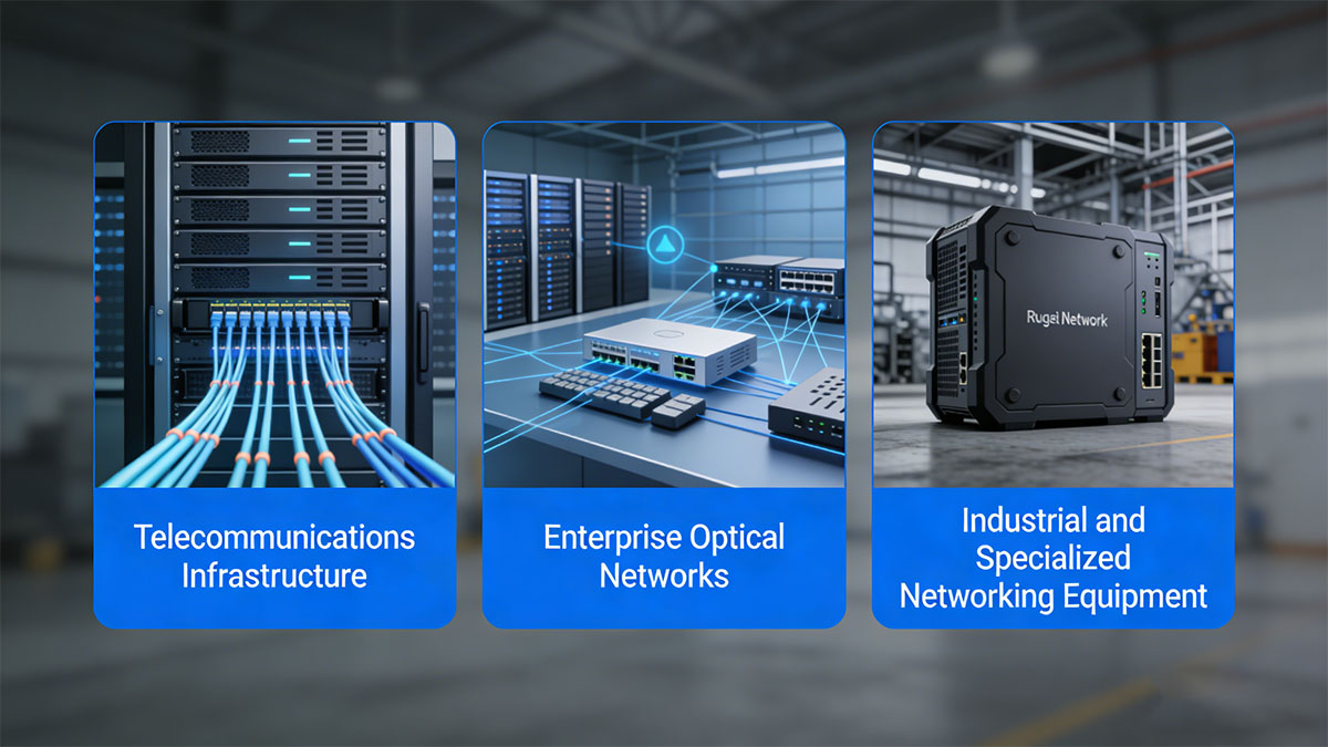
Telecommunications Infrastructure
SFF transceivers were frequently integrated into telecommunications equipment used for optical transport and carrier networks. In these environments, optical interfaces are often embedded directly into system hardware, making board-mounted modules a practical design choice.
Common telecom equipment that may incorporate SFF optical modules includes:
- Optical add-drop multiplexers (OADM)
- Digital cross-connect systems (DCS)
- SONET/SDH transport platforms
- Carrier-grade network switches
The following table summarizes typical characteristics of SFF deployment in telecom infrastructure.
| Deployment Environment |
Network Role |
Typical Optical Standard |
| Access Networks |
Connect local exchange equipment |
OC-3 / STM-1 |
| Metro Transport |
Aggregation and regional links |
OC-12 / STM-4 |
| Core Transport |
High-capacity backbone |
OC-48 / STM-16 |
These applications benefit from the reliability and long operational lifespan associated with integrated optical interfaces.
Enterprise Optical Networks
Enterprise networks were another major environment where SFF transceivers were deployed, particularly during the early adoption of fiber-based Gigabit Ethernet backbones.
Organizations often used SFF optical modules to extend network connectivity between switches, buildings, or campus network segments.
Typical enterprise deployment scenarios include:
- Campus backbone connectivity between distribution switches
- Inter-building fiber links connecting different facilities
- Data center aggregation layers in earlier Gigabit Ethernet architectures
- Fiber uplinks for enterprise switches
These deployments often relied on standards such as 100BASE-FX sfp, 1000BASE-SX sfp, and 1000BASE-LX sfp, depending on bandwidth requirements and transmission distance.
Even though many modern enterprise switches now use pluggable optics, some legacy systems continue to operate with integrated SFF optical interfaces.
Industrial and Specialized Networking Equipment
Industrial networking environments frequently use hardware platforms with long product lifecycles. In such systems, optical interfaces are often integrated into the device rather than designed for frequent replacement.
SFF transceivers can still be found in specialized equipment such as:
- Industrial Ethernet switches
- Transportation control systems
- Power utility communication networks
- Manufacturing automation systems
The table below outlines typical characteristics of SFF modules in industrial networking applications.
| Application Sector |
Network Function |
Deployment Characteristics |
| Industrial Automation |
Machine and controller connectivity |
Stable fixed optical interfaces |
| Transportation Systems |
Communication between control nodes |
Long equipment lifecycle |
| Energy and Utilities |
Monitoring and control networks |
High reliability requirements |
In these environments, the stability of board-mounted optical modules and the long-term availability of compatible components are often more important than modular flexibility.
As a result, SFF transceivers continue to support operational networks in sectors where equipment upgrades occur less frequently and system reliability is a primary concern.
⏳ SFF vs Other Optical Transceiver Form Factors
SFF transceivers represent an important stage in the evolution of optical module design. As network bandwidth requirements increased and equipment density became more critical, new form factors were introduced to improve flexibility, scalability, and serviceability.
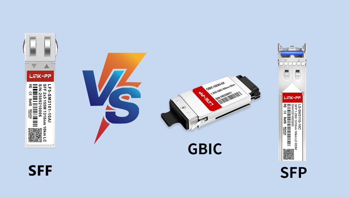
Understanding how SFF modules compare with other optical transceiver types—particularly GBIC and SFP—helps explain why the industry gradually transitioned toward hot-pluggable optical interfaces.
SFF vs GBIC
SFF modules were introduced as a smaller alternative to GBIC (Gigabit Interface Converter) transceivers. While GBIC modules were widely used in early Gigabit Ethernet equipment, their larger size limited port density in networking devices.
The table below highlights the main differences between these two form factors.
| Feature |
SFF Transceiver |
GBIC Module |
| Physical Size |
Smaller footprint |
Larger module |
| Installation Method |
Board-mounted |
Hot-pluggable |
| Port Density |
Higher density potential |
Lower density |
| Typical Use Period |
Later-generation compact systems |
Early Gigabit Ethernet hardware |
The reduced size of SFF modules allowed equipment manufacturers to design more compact switches and telecom systems. However, because SFF transceivers were integrated into the device circuit board, replacing or upgrading them required hardware servicing.
SFF vs SFP
The introduction of SFP (Small Form-factor Pluggable) modules marked a major shift in optical transceiver design. SFP modules maintain a compact size similar to SFF optics but add the advantage of hot-swappable functionality.
The following table summarizes the differences between SFF and SFP optical modules.
| Feature |
SFF Transceiver |
SFP Module |
| Installation Type |
Board-mounted |
Hot-pluggable |
| Maintenance |
Requires hardware access |
Easily replaceable |
| Flexibility |
Fixed optical interface |
Supports multiple module types |
| Typical Applications |
Integrated telecom hardware |
Modern network switches and routers |
Because SFP modules can be inserted or removed without powering down the device, they offer greater operational flexibility. Network operators can change optical types, transmission distances, or wavelengths simply by replacing the pluggable module.
This capability made SFP optics a widely adopted solution for enterprise networks, data centers, and telecommunications infrastructure.
Evolution of Optical Transceiver Form Factors
The progression of optical module form factors reflects the increasing demand for higher network capacity and greater operational flexibility. Each generation introduced improvements in size, performance, or serviceability.
The evolution of common optical transceiver designs can be summarized as follows.
| Generation |
Form Factor |
Key Improvement |
| Early Generation |
GBIC |
Pluggable optical interface |
| Compact Generation |
SFF |
Reduced physical size |
| Modern Generation |
SFP |
Small size with hot-swappable design |
| High-Density Generation |
QSFP / QSFP-DD |
Multi-lane high-speed optics |
This evolution demonstrates how optical networking technology has adapted to changing requirements such as higher bandwidth, increased port density, and easier hardware maintenance.
While SFF modules played a key role in enabling compact optical interfaces, later form factors eventually combined compact design with the flexibility required for modern network operations.
⏳ Advantages and Limitations of SFF SFP Transceivers
SFF transceivers were developed to improve the compactness of optical networking hardware while maintaining stable fiber communication performance. Their design offered several advantages for equipment manufacturers and network operators, especially in systems where optical interfaces were intended to remain fixed.
At the same time, the evolution of pluggable optical modules introduced new capabilities that gradually reduced the use of board-mounted optics. Understanding both the strengths and limitations of SFF transceivers helps explain their role in legacy systems and why newer form factors became more widely adopted.
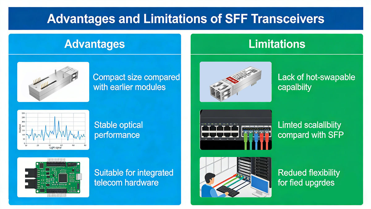
Advantages
SFF transceivers provided several practical benefits when they were first introduced, particularly for networking hardware that required compact optical integration.
Some of the main advantages include:
- Compact physical size
The small form factor allows networking devices to integrate more optical interfaces within limited space.
- Stable integrated design
Because the module is mounted directly on the circuit board, the optical interface becomes a permanent part of the hardware, which can improve mechanical stability.
- Efficient use of internal device space
Board-mounted optics eliminate the need for pluggable cages or external module slots.
- Suitable for fixed optical interfaces
Many telecom and industrial devices are designed with predetermined optical configurations, making integrated modules a practical solution.
The table below summarizes the core advantages of SFF optical modules.
| Advantage |
Description |
Impact |
| Compact Form Factor |
Smaller footprint than earlier optics |
Higher port density |
| Integrated Hardware Design |
Board-mounted installation |
Improved structural stability |
| Simplified Mechanical Structure |
No external module cage required |
Efficient hardware layout |
| Reliable Optical Performance |
Designed for fixed deployment |
Long-term system stability |
These characteristics made SFF transceivers particularly useful in telecom transport equipment and embedded networking platforms where reliability and compact design were key priorities.
Limitations
Despite their advantages, SFF transceivers also have several limitations compared with modern pluggable optical modules. These limitations are primarily related to flexibility, maintenance, and scalability.
Key limitations include:
- Lack of hot-swappable capability
Because SFF modules are soldered or mounted directly on the circuit board, they cannot be replaced without opening the device or performing hardware servicing.
- Limited upgrade flexibility
Changing transmission distance, wavelength, or optical standard typically requires replacing the entire hardware unit rather than simply swapping modules.
- Reduced scalability for evolving networks
Modern networks often require frequent upgrades to support higher bandwidth or new optical technologies.
The table below summarizes these constraints.
| Limitation |
Description |
Operational Impact |
| Non-Pluggable Design |
Module integrated into hardware |
Difficult field replacement |
| Fixed Optical Configuration |
Limited ability to change optics |
Reduced deployment flexibility |
| Maintenance Complexity |
Hardware access required for repair |
Longer service procedures |
| Lower Scalability |
Harder to upgrade optical interfaces |
Less adaptable to network growth |
As networking technology advanced, these limitations encouraged the industry to adopt pluggable optical form factors such as SFP and QSFP. These newer designs offer greater flexibility, allowing network operators to modify optical configurations without replacing the entire device.
Nevertheless, SFF transceivers continue to support many legacy systems where the original hardware architecture relies on integrated optical interfaces and long-term operational stability.
⏳ Considerations When Using SFF Optical Modules
When deploying or maintaining systems that use SFF optical modules, several technical factors must be evaluated to ensure stable network operation. Because SFF transceivers are typically integrated into hardware platforms rather than designed for frequent replacement, compatibility, fiber planning, and thermal management become especially important.
Carefully reviewing these considerations helps network operators maintain reliable fiber connections and avoid performance issues in systems that rely on SFF optical interfaces.
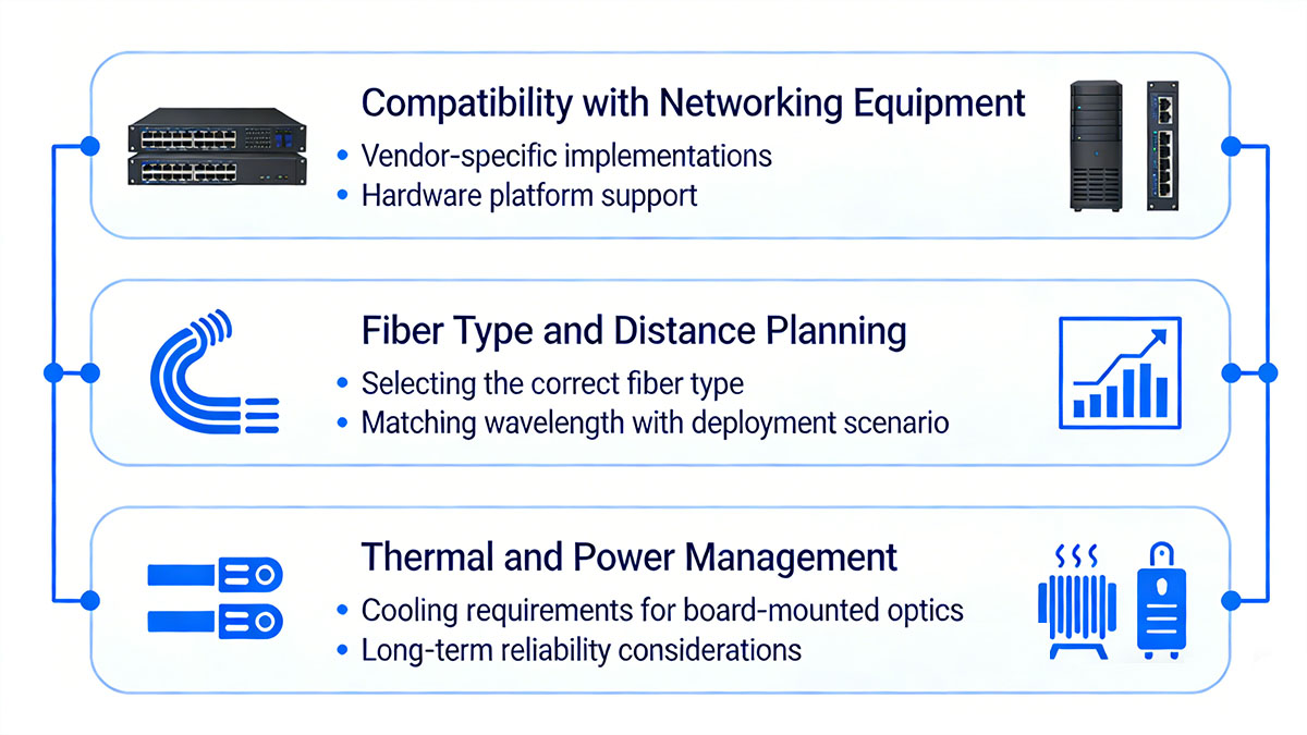
Compatibility with Networking Equipment
The first consideration when working with SFF optical modules is ensuring compatibility with the networking equipment in which they are installed. Since SFF modules are usually board-mounted, they are often designed specifically for a particular hardware platform.
Key compatibility factors include:
- Hardware interface design – the module must match the device’s electrical interface and pin configuration
- Supported network standards – the fiber transceivers must support the same Ethernet or SONET/SDH protocol used by the equipment
- Optical parameters – wavelength, power levels, and sensitivity must align with the system design
- Connector compatibility – the module connector must match the existing fiber infrastructure
The following table summarizes typical compatibility checks.
| Compatibility Factor |
What to Verify |
Impact on Operation |
| Electrical Interface |
Pin layout and signal type |
Ensures proper device communication |
| Network Standard |
Ethernet or SONET/SDH support |
Prevents protocol mismatch |
| Optical Specifications |
Wavelength and power levels |
Maintains stable signal transmission |
| Fiber Connector Type |
LC, SC, or other connectors |
Ensures physical connectivity |
Because these modules are integrated into device hardware, compatibility verification is typically performed during system design or equipment maintenance.
Fiber Type and Distance Planning
Selecting the correct fiber type and link distance is another important consideration when using SFF optical modules. Optical performance depends heavily on matching the module wavelength with the appropriate fiber infrastructure.
Typical planning considerations include:
- Fiber type selection
Multimode fiber is typically used for shorter links, while single-mode fiber supports longer transmission distances.
- Transmission distance requirements
The optical module must support the required link length without excessive signal attenuation.
- Wavelength compatibility
Different wavelengths are optimized for specific fiber types and transmission ranges.
The relationship between fiber type, wavelength, and distance can be summarized as follows.
Proper planning helps prevent signal loss, link instability, and performance degradation in fiber optic communication systems.
Thermal and Power Management
Thermal and power considerations are also important when designing or maintaining equipment that uses SFF optical modules. Because these modules are mounted directly onto the circuit board, they rely on the device’s overall cooling design for heat dissipation.
Key factors to consider include:
- Power consumption
Optical modules draw electrical power from the host device, and total system power budgets must account for multiple transceivers.
- Heat dissipation
Laser diodes and signal processing circuits generate heat during operation, which must be properly managed to maintain stable performance.
- Operating temperature range
Equipment used in industrial or telecom environments may experience wider temperature fluctuations.
The table below summarizes common thermal considerations.
| Parameter |
Typical Range |
Importance |
| Power Consumption |
0.5W–1.5W |
Affects system power budget |
| Operating Temperature |
0°C to 70°C |
Ensures stable operation |
| Thermal Dissipation |
Device cooling dependent |
Prevents overheating |
Adequate cooling design, airflow management, and power planning help ensure long-term reliability for networking equipment that incorporates SFF optical modules.
⏳ FAQs About SFF Transceivers
What does SFF mean in optical transceivers?
SFF stands for Small Form Factor, referring to a compact optical transceiver design used in fiber optic networking equipment. SFF modules were developed to reduce the physical size of optical interfaces compared with earlier solutions while maintaining reliable data transmission.
Are SFF transceivers hot-swappable?
No. SFF transceivers are typically board-mounted optical modules integrated directly into networking hardware. Unlike pluggable modules such as SFP, they cannot be inserted or removed while the device is running.
What data rates do SFF transceivers support?
SFF transceivers commonly support 100Mbps Fast Ethernet, 1Gbps Gigabit Ethernet, and certain SONET/SDH rates such as OC-3 and OC-12. The supported data rate depends on the specific module design and network standard.
What connectors are commonly used with SFF optical modules?
Most SFF optical modules use LC or SC fiber connectors for duplex fiber links. The connector type depends on the hardware design and the fiber infrastructure used in the network.
Are SFF transceivers still used today?
SFF transceivers are mainly used in legacy networking equipment, telecom transport systems, and specialized industrial hardware where optical interfaces are integrated into the device and long hardware lifecycles are common.
What is the difference between SFF and SFP transceivers?
The main difference is the installation method. SFF modules are board-mounted and fixed within the device, while SFP modules are hot-pluggable optical transceivers that can be easily inserted or replaced without opening the equipment.
⏳ Conclusion
SFF transceivers played an important role in the evolution of fiber optic networking by introducing a more compact optical interface compared with earlier module designs. Their small form factor allowed equipment manufacturers to integrate higher port density into telecom systems, enterprise switches, and specialized networking hardware while maintaining reliable optical performance.
Although modern networking environments widely use hot-pluggable modules such as SFP and higher-speed form factors, SFF optical modules remain relevant in many legacy platforms and long-lifecycle systems. Understanding their structure, technical characteristics, standards, and typical applications helps network engineers maintain existing infrastructure and better evaluate compatibility when working with older networking equipment.
For organizations maintaining fiber networks or supporting legacy optical systems, selecting reliable optical components remains an important part of ensuring long-term network stability. If you want to explore more information about optical transceivers and compatible fiber solutions, you can visit the LINK-PP Official Store to learn about available optical networking products and technical resources.


