
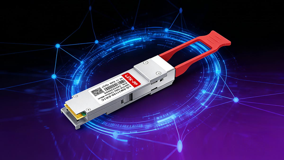
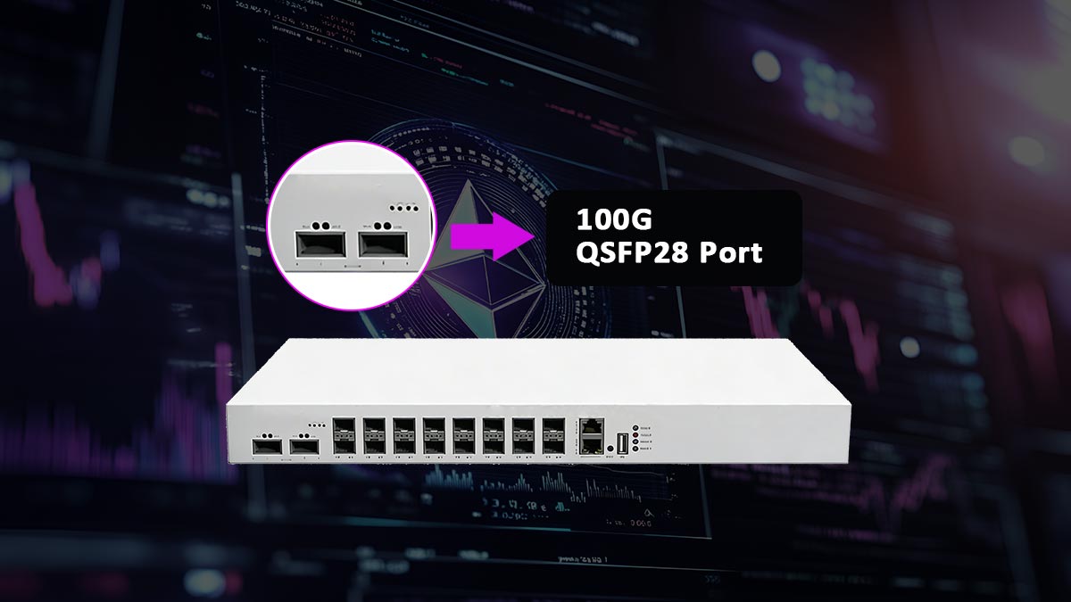
As data centers, cloud platforms, and telecom networks continue to scale, 100G connectivity has become a foundational requirement rather than an upgrade option. Among the various high-speed optical form factors available today, 100G QSFP28 Transceivers have emerged as the industry standard for delivering reliable, cost-effective 100-gigabit Ethernet links across a wide range of deployment scenarios.
QSFP28 transceivers combine a compact form factor with high port density, supporting applications from short-reach data center interconnects to long-haul metro and telecom networks. However, with multiple module types—such as SR4, LR4, CWDM4, and ZR4—each optimized for different distances, fiber types, and network architectures, selecting the right 100G QSFP28 transceiver can be challenging.
Misunderstanding specifications, overlooking compatibility requirements, or choosing an inappropriate reach class can lead to performance issues, unnecessary costs, or deployment delays. This makes a structured, engineering-focused understanding of how 100G QSFP28 transceivers work, how they differ, and how to choose the right one essential for network engineers, system integrators, and procurement teams.
In this guide, we provide a comprehensive, practical overview of 100G QSFP28 modules, covering their working principles, module types, key specifications, typical applications, and a step-by-step selection framework to help you make confident, informed decisions for your network.
? What Is 100G QSFP28?
100G QSFP28 is a hot-pluggable optical transceiver form factor designed to deliver 100-gigabit Ethernet connectivity using four parallel 25-gigabit lanes.
It is widely used in data centers, enterprise core networks, and telecom infrastructure due to its high port density, standardized interface, and broad ecosystem support.
QSFP28 stands for Quad Small Form-factor Pluggable 28, indicating four electrical lanes, each capable of operating up to 25 Gbps, aggregated to achieve a total throughput of 100 Gbps.
QSFP28 Form Factor and 4×25G Lane Architecture
From a hardware and signaling perspective, 100G QSFP28 is built on a 4×25G lane architecture, a design approach clearly described by Starview Technologies.
Key architectural characteristics include:
-
Four electrical lanes, each operating at 25 Gbps
-
Aggregate bandwidth of 100 Gbps (4 × 25G)
-
Support for parallel optics (SR4, PSM4) and wavelength-multiplexed optics (LR4, CWDM4, ER4, ZR4)
-
Compact QSFP form factor enabling high-density switch designs
Depending on the optical module type, these four lanes may be transmitted as:
-
Four parallel optical channels over multi-mode or single-mode fiber, or
-
Four wavelengths multiplexed onto a single pair of single-mode fibers
This modular lane-based architecture is what allows QSFP28 to support a wide range of distances and deployment scenarios while maintaining a common electrical interface.
When and Why Networks Use QSFP28 vs Older Form Factors
Networks adopt QSFP28 primarily to address bandwidth scaling and port density limitations found in earlier transceiver generations.
Compared with older form factors:
-
Versus SFP+ (10G)
QSFP28 delivers ten times the bandwidth in a single module, significantly reducing the number of ports, cables, and power consumption required for high-capacity links.
-
Versus QSFP+ (40G)
QSFP28 offers higher bandwidth within the same physical footprint, enabling seamless upgrades from 40G to 100G without redesigning switch hardware.
-
Versus CFP-based 100G modules
QSFP28 provides a much smaller form factor, lower power consumption, and better suitability for high-density data center environments.
As a result, QSFP28 has become the de facto standard for 100G Ethernet, balancing performance, scalability, and operational efficiency across modern network architectures.
100G QSFP28 at a Glance
| Parameter |
Description |
| Form Factor |
QSFP28 (Quad Small Form-factor Pluggable 28) |
| Total Data Rate |
100 Gbps |
| Lane Architecture |
4 × 25 Gbps (4×25G) |
| Electrical Interface |
4-lane electrical interface compliant with IEEE 802.3 |
| Modulation Type |
NRZ (most 100G QSFP28 variants) |
| Fiber Type |
MMF or SMF (depends on module type) |
| Typical Wavelengths |
850 nm (SR4), 1310 nm (LR4/PSM4), CWDM range |
| Transmission Distance |
From 100 m to 80 km (module-dependent) |
| Connector Type |
MPO-12 / MPO-8 or Duplex LC |
| Hot-Pluggable |
Yes |
| Power Consumption |
Typically 2.5 W – 5 W (varies by optics) |
| Standards Compliance |
IEEE 802.3bm / 802.3ba, QSFP28 MSA |
| Common Applications |
Data centers, enterprise core, telecom networks |
? How 100G QSFP28 Transceivers Work
A 100G QSFP28 transceiver splits 100G data into four 25 Gbps lanes, converts electrical signals into optical signals for fiber transmission, and reconverts received light into electrical data using NRZ modulation for efficient, high-density network connectivity.
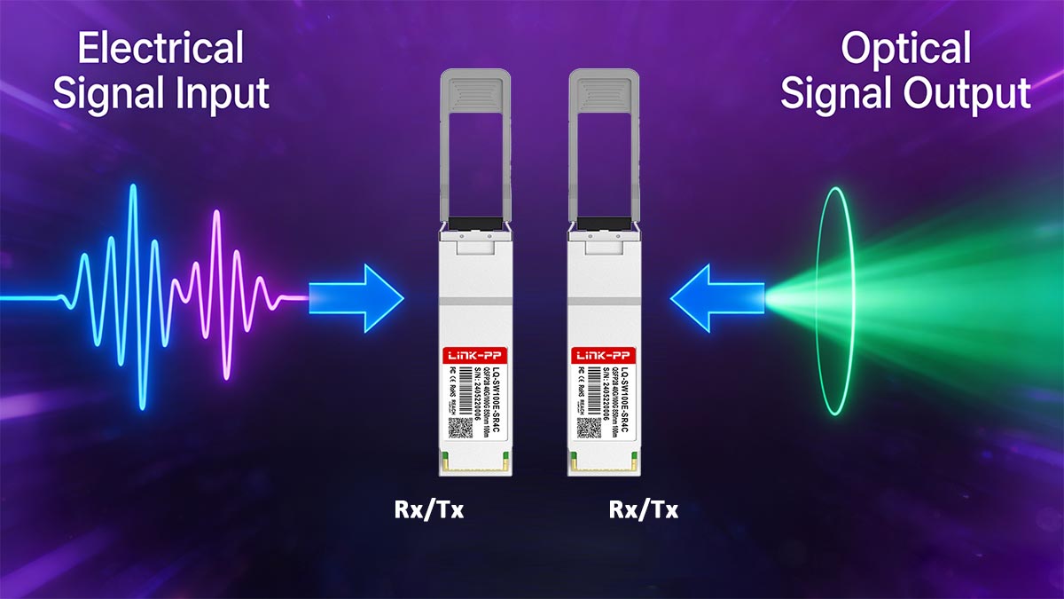
① Electrical-to-Optical Signal Conversion (4×25G Lanes)
On the transmit (TX) side, the QSFP28 module interfaces with the host switch ASIC through four independent 25 Gbps electrical lanes.
TX signal flow:
-
The switch ASIC outputs 4 × 25G NRZ electrical signals
-
Each lane undergoes equalization and signal conditioning
-
Signals are driven into laser drivers or optical modulators
-
Electrical signals are converted into optical pulses for transmission
This multi-lane approach enables 100G throughput without increasing module size, distinguishing QSFP28 from earlier 10G-based QSFP+ designs.
② Optical Transmission Architectures in QSFP28
QSFP28 supports multiple optical implementations to balance reach, fiber usage, and cost.
Parallel Optics (SR4 / PSM4)
Best suited for:
Intra-data-center links requiring low latency and simple optical design.
Wavelength Division Multiplexing (LR4 / CWDM4)
Best suited for:
Data center interconnect (DCI) and metro-scale deployments where fiber efficiency matters.
③ Optical-to-Electrical Conversion (RX Direction)
On the receive (RX) side, the process is reversed:
-
Incoming optical signals are captured by photodiodes
-
Signals are separated by lane or wavelength
-
Optical signals are converted back into electrical form
-
The module outputs 4 × 25G electrical lanes to the host
Advanced signal conditioning and error correction maintain integrity across longer distances.
④ Why QSFP28 Enables High Density and Efficiency
QSFP28 achieves its efficiency through:
-
4×25G lane-based architecture
-
NRZ modulation with strong noise margins
-
Optimized power envelopes for 100G platforms
-
Backward-compatible QSFP cages
This allows network designers to scale to 100G without redesigning hardware, making QSFP28 the dominant 100G form factor.
⑤ PAM4 Basics and Link Budget Implications
Although most 100G QSFP28 modules use NRZ, PAM4 is relevant for comparison with higher-speed optics.
PAM4 vs NRZ (Key Differences)
Implication:
QSFP28 (NRZ) offers simpler, more predictable link budgets—especially in legacy or mixed-fiber environments.
⑥ DDM Monitoring and Hot-Plug Operation
DDM (Digital Diagnostic Monitoring)
QSFP28 modules support DDM/DOM via I²C, reporting:
-
Temperature
-
Supply voltage
-
Laser bias current
-
TX/RX optical power
This enables proactive fault detection and link health validation.
Hot-Plug Capability
QSFP28 transceivers are fully hot-pluggable, supported by:
Best practice:
Verify platform compatibility and allow initialization time after insertion.
A 100G QSFP28 transceiver works by distributing data across four 25G lanes, converting electrical signals to optical signals using either parallel optics or wavelength multiplexing, and delivering efficient, high-density 100G connectivity—supported by robust NRZ modulation, real-time monitoring, and hot-plug operation.
? Types of 100G QSFP28 Modules (SR4, LR4, CWDM4, PSM4, BiDi, ER4, ZR4, eZR4+)
100G QSFP28 transceivers are available in multiple optical variants to address different reach requirements, fiber infrastructures, and cost models.
The main differences lie in how the four 25G lanes are transmitted—either across multiple fibers, multiple wavelengths, or bidirectionally.
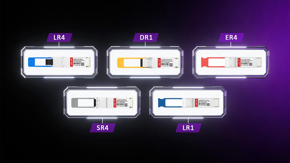
4-Lambda QSFP28 Modules (SR4 / LR4 / ER4 / ZR4)
4-lambda QSFP28 modules transmit four parallel 25G signals, either as parallel fibers (SR4) or multiplexed wavelengths (LR4-class optics). This category covers the widest range of distances.
4-Lambda Wavelength & Distance Overview
| Module Type |
Fiber Type |
Wavelengths |
Connector |
Typical Reach |
Common Use Case |
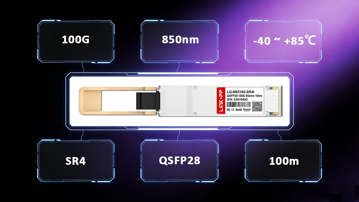
| 100G SR4 |
MMF |
850 nm (×4) |
MPO-12 |
70–100 m |
Intra-DC, ToR–EoR |
| 100G LR4 |
SMF |
1295–1310 nm (4λ) |
LC duplex |
10 km |
DC interconnect, enterprise core |
| 100G ER4 |
SMF |
1295–1310 nm (4λ) |
LC duplex |
30–40 km |
Metro, aggregation |
| 100G ZR4 |
SMF |
1295–1310 nm (4λ) |
LC duplex |
80 km |
Long-haul DCI |
| 100G eZR4+ |
SMF |
Extended 4λ CWDM |
LC duplex |
80–100 km |
High-budget DCI |
Key characteristics:
-
True 4×25G lane architecture
-
Excellent standards interoperability (IEEE 802.3)
-
Higher optical complexity and cost at longer reaches
-
Preferred for mission-critical and long-distance links
Single-Lambda 100G QSFP28 Modules (DR1 / FR1 / LR1)
Single-lambda QSFP28 modules transmit 100G over a single wavelength, typically using PAM4 modulation instead of NRZ.
| Module Type |
Fiber |
Wavelength |
Reach |
Typical Power |
| 100G DR1 |
SMF |
~1310 nm |
500 m |
Low |
| 100G FR1 |
SMF |
~1310 nm |
2 km |
Medium |
| 100G LR1 |
SMF |
~1310 nm |
10 km |
Higher |
Advantages:
-
Simplified optical design
-
Lower fiber count
-
Potentially lower cost at scale
-
Optimized for next-generation leaf-spine architectures
Trade-offs:
These modules are increasingly used in hyperscale data centers, but are less tolerant of legacy fiber environments.
CWDM4 / PSM4 / BiDi — Cost vs Complexity Trade-Offs
This category focuses on reducing cost or fiber usage compared to traditional LR4 optics.
CWDM4
Best for:
Cost-optimized data center interconnects where 10 km reach is unnecessary.
PSM4
-
4 parallel fibers on SMF
-
MPO connector
-
Reach up to 500 m–2 km
Best for:
Data centers with existing MPO cabling and short-reach SMF links.
BiDi (Bi-Directional)
-
Two wavelengths per fiber
-
100G transmitted over one duplex MMF or SMF pair
-
Often backward-compatible with legacy MMF
Best for:
Fiber-constrained environments where upgrading cabling is impractical.
Practical Selection Summary
-
Maximum reach & standards compliance: LR4 / ER4 / ZR4
-
Lowest latency & simple optics: SR4 / PSM4
-
Cost-optimized DCI: CWDM4
-
Fiber-limited upgrades: BiDi
-
Hyperscale & next-gen designs: DR1 / FR1 / LR1
Each QSFP28 type reflects a deliberate trade-off between distance, power consumption, fiber efficiency, and cost, making correct selection critical for long-term network performance.
? 100G QSFP28 Specifications You Should Know
When designing or deploying 100G links, understanding QSFP28 specifications is essential for ensuring compatibility, performance, and long-term reliability.
Among all parameters, engineers most frequently evaluate wavelength and reach, power and thermal limits, and optical link budget, as these factors directly determine whether a QSFP28 100G Modules will operate stably in a given network environment.
This section focuses on the core engineering specifications that matter in real-world deployments—helping network designers avoid common pitfalls such as fiber mismatch, insufficient power margins, or thermal constraints in high-density switch platforms.
Wavelength, Reach, Fiber Type, and Connector
The optical interface of a 100G QSFP28 transceiver determines maximum transmission distance, fiber compatibility, and connector selection.
Key parameters to verify
- Wavelength
-
850 nm (SR4, MMF)
-
~1310 nm (LR4 / CWDM4 / DR1 / FR1 / LR1, SMF)
-
CWDM wavelength set (CWDM4, ZR4-class)
-
Transmission reach
-
Fiber type
-
MMF (OM3 / OM4 / OM5): SR4, BiDi
-
SMF (G.652 / G.655): LR4, CWDM4, ER4, ZR4, DR1
-
Connector type
-
MPO-12 / MPO-8: SR4, PSM4
-
Duplex LC: LR4, CWDM4, ER4, ZR4, single-lambda modules
Incorrect matching of wavelength and fiber type is a primary cause of link instability and non-link conditions.
Power Consumption and Thermal Considerations
Power and thermal characteristics directly affect port density and long-term reliability.
Typical power envelopes
Thermal design considerations
-
Ensure sufficient airflow across QSFP cage
-
Verify platform firmware power limits
-
Avoid placing high-power optics in thermally constrained ports
Modules operating near maximum temperature thresholds experience accelerated aging and higher failure rates.
Optical Power, Receiver Sensitivity, and Link Budget
Link budget defines whether a QSFP28 100G optical link will operate reliably under real-world conditions.
Core optical parameters
-
Transmit optical power (Tx):
Determines how far the signal can travel before attenuation causes errors
-
Receiver sensitivity (Rx):
Minimum optical power required for acceptable BER
-
Optical return loss (ORL):
Important for long-reach SMF deployments
Typical link budget ranges
-
SR4: ~1.9–2.3 dB
-
CWDM4 / LR4: ~6–8 dB
-
ER4: ~18–20 dB
-
ZR4: 28 dB+
Practical link budget calculation
Link budget = Tx output power − Rx sensitivity − total system loss
(system loss includes fiber attenuation, connector loss, splices, and aging margin)
Engineering note:
Always reserve 2–3 dB system margin to account for connector contamination, fiber aging, and temperature variation.
100G QSFP28 Engineering Spec Checklist
Correct selection of wavelength, fiber type, power envelope, and link budget ensures stable 100G QSFP28 operation.
Ignoring any of these parameters significantly increases deployment risk—especially in long-reach or high-density environments.
| Category |
Key Parameters to Verify |
Engineering Purpose |
| Wavelength |
850 nm / ~1310 nm / CWDM |
Match optics to fiber type and reach |
| Transmission Reach |
100 m – 80 km+ |
Ensure distance meets network design |
| Fiber Type |
MMF (OM3/OM4/OM5) / SMF (G.652) |
Prevent fiber–wavelength mismatch |
| Connector Type |
MPO-12 / MPO-8 / LC duplex |
Ensure physical compatibility |
| Power Consumption |
2.5 W – 6 W |
Stay within switch power limits |
| Thermal Requirements |
Adequate airflow, platform cooling |
Prevent overheating and throttling |
| Tx Optical Power |
Module-specific (dBm) |
Support required link distance |
| Rx Sensitivity |
Module-specific (dBm) |
Ensure reliable signal detection |
| Link Budget |
2 dB – 28 dB+ |
Validate total system loss margin |
| System Margin |
≥ 2–3 dB |
Account for aging and contamination |
| Modulation |
NRZ / PAM4 |
Assess SNR and FEC requirements |
| DDM Support |
Yes / Required |
Enable real-time monitoring |
| Hot-Plug Capability |
Supported |
Ensure operational flexibility |
? How to Choose the Right 100G QSFP28 Transceiver
Choosing the right QSFP28 100G transceiver is a structured engineering decision—not just a matter of speed or distance.
A reliable selection process should move from platform capability, to optical feasibility, then to compatibility validation, and finally to procurement and lifecycle considerations.
The following decision flow reflects how experienced network engineers and architects evaluate QSFP28 optics in production networks.
Match Port and Switch Capability
Start by validating what the switch or router can actually support.
Key checks
-
Port type: QSFP28 (not QSFP+)
-
Supported optics classes: SR4, LR4, CWDM4, ER4, etc.
-
Maximum per-port power budget
-
FEC requirements (mandatory for PAM4-based modules)
Even if a module is electrically compatible, firmware or hardware limits may:
Always verify vendor platform documentation before selecting the transceiver.
Calculate Link Budget and Choose the Right Reach Class
Link budget analysis ensures the optical signal remains above the receiver sensitivity threshold after all losses.
Step-by-step approach
-
Determine fiber type and distance
-
Identify connector and splice loss
-
Add aging and safety margin (≥ 2–3 dB)
-
Select a QSFP28 100G reach class with sufficient budget
Practical guidance
-
Short links (<100 m): SR4
-
Medium SMF links (≤2 km): CWDM4 / DR1
-
Long links (10 km+): LR4 / ER4 / ZR4
Over-specifying reach increases cost and power consumption, while under-specifying reach risks unstable links.
Compatibility and Vendor Lock Checks (EEPROM, Vendor Coding)
Many network platforms enforce optics authentication via EEPROM coding.
What to verify
-
Vendor lock policies on the switch
-
EEPROM compatibility (vendor ID, part number)
-
Ability to support third-party or MSA-compliant optics
High-quality QSFP28 third-party modules can deliver:
…but only when correctly coded and validated for the target platform.
Procurement Checklist (Price, Lead Time, QA & Warranty)
Final selection should consider total cost of ownership, not just unit price.
Procurement factors
-
Price band: OEM vs third-party
-
Lead time: stock availability vs build-to-order
-
Quality assurance: testing, burn-in, traceability
-
Warranty & support: replacement policy, lifecycle coverage
Engineering insight
Consistent QA processes and clear warranty terms are especially important for:
A successful 100Gb QSFP28 selection aligns:
Following this decision flow reduces deployment risk, optimizes cost, and ensures long-term network stability.
? Common 100G QSFP28 Deployment Issues & Troubleshooting
Despite being a mature and widely deployed standard, 100G QSFP28 links can still fail due to configuration mismatches, optical constraints, or platform restrictions.
Can QSFP28 Run at Lower Speeds?
Short answer: It depends on the switch platform and breakout configuration.
Typical scenarios
-
100G → 4×25G breakout:
Supported on most QSFP28 ports using breakout cables (QSFP28 to 4×SFP28)
-
100G → 40G (QSFP+ mode):
Not universally supported
Some platforms allow limited backward compatibility, others do not
-
100G → 10G:
Generally not supported directly due to electrical lane differences
QSFP28 ports are electrically optimized for 4×25G lanes.
Lower-speed operation requires explicit platform support and correct port configuration.
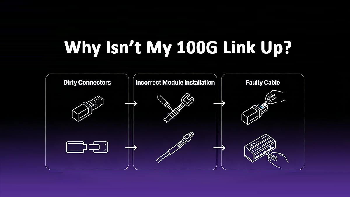
Why Isn’t My 100G Link Up?
Most 100G link failures can be traced to a small set of root causes.
Common causes to check
1️⃣ Wavelength mismatch
2️⃣ Fiber polarity or lane mapping errors
3️⃣ Insufficient SNR or link budget
-
Excessive fiber attenuation
-
Dirty or damaged connectors
-
Insufficient system margin
4️⃣ FEC configuration mismatch
Engineering checklist
-
Verify wavelength and fiber type
-
Inspect and clean connectors
-
Confirm link budget calculations
-
Validate FEC and port configuration
Third-Party Module Compatibility and Firmware Issues
Third-party QSFP28 modules are widely used, but compatibility depends on platform policies.
Common compatibility challenges
-
Vendor lock enforcement via EEPROM
-
Firmware rejecting unrecognized optics
-
Disabled DDM reporting
-
Port shutdown due to power class limits
Best practices
-
Use platform-qualified or correctly coded modules
-
Match firmware version with optics support matrix
-
Validate DDM functionality after installation
-
Avoid mixing unsupported optics in critical links
Well-tested third-party QSFP28 modules can deliver OEM-equivalent performance—provided EEPROM coding and firmware compatibility are properly managed.
Most 100G QSFP28 issues are not caused by defective optics, but by configuration mismatches, fiber errors, or platform restrictions.
A systematic troubleshooting approach dramatically reduces downtime and deployment risk.
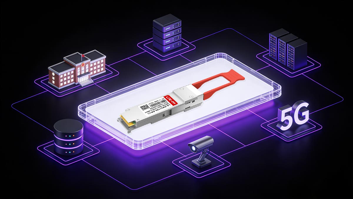
? Typical Applications of 100G QSFP28 Transceiver
100G QSFP28 transceivers are widely deployed across modern network architectures due to their high bandwidth density, predictable performance, and mature ecosystem.
Their flexibility in reach and optical design makes them suitable for everything from short-reach data center links to long-haul interconnects.
Data Centers and Cloud Infrastructure
In hyperscale and enterprise data centers, QSFP28 is the workhorse interface for 100G leaf–spine architectures.
Typical use cases:
Common optics:
-
QSFP28 SR4 100G for short intra-rack links
-
CWDM4 / DR1 for cost-optimized inter-row connections
-
100G QSFP28 LR4 for extended data hall or campus-scale deployments
Why QSFP28 fits:
High port density, low power consumption, and broad switch compatibility enable scalable 100G designs without major infrastructure changes.
Enterprise and Campus Core Networks
Enterprises and large campuses increasingly rely on 100G QSFP28 to support core and aggregation layer upgrades.
Typical use cases:
-
Core switch interconnects
-
Building-to-building fiber links
-
High-performance computing clusters
Common optics:
Why QSFP28 fits:
Reliable NRZ modulation and predictable link budgets make QSFP28 suitable for mixed-vendor and legacy fiber environments.
Telecom, DCI, and Service Provider Networks
Telecom operators and service providers use QSFP28 in aggregation, access, and interconnect layers.
Typical use cases:
-
Data Center Interconnect (DCI)
-
Metro aggregation networks
-
FTTx and 5G fronthaul/backhaul
Common optics:
Why QSFP28 fits:
Support for long reach, strong link budgets, and mature standards compliance make QSFP28 a trusted choice for carrier-grade networks.
Across data centers, enterprises, and telecom networks, 100G QSFP28 transceivers deliver a balance of:
This versatility is a key reason QSFP28 remains the dominant 100G optical interface in production networks worldwide.
?Summary: QSFP28 100G Module Solutions
As networks evolve toward ever-higher bandwidth and more demanding performance requirements, choosing the right 100G QSFP28 transceiver means balancing compatibility, optical reach, power efficiency, and long-term reliability. A proper selection process ensures your 100G links perform reliably across data center aggregation, enterprise backbone, telecom aggregation, and long-haul interconnect environments—while minimizing deployment risk and lifecycle costs.
To recap, in this guide you learned how 100G QSFP28 works, the differences between common module types (SR4, LR4, CWDM4, ER4, ZR4, single-lambda variants), key specifications to validate (wavelength, reach, link budget, power), how to troubleshoot common deployment issues, and practical criteria for selecting the right module for your topology and fiber plant.
LINK-PP 100G QSFP28 Transceiver Solutions
For engineers and procurement teams looking to deploy or upgrade to 100G networks with confidence, LINK-PP offers a comprehensive portfolio of 100G optical transceivers that support both QSFP28 and next-generation form factors like SFP-DD, designed for reliability and broad compatibility.
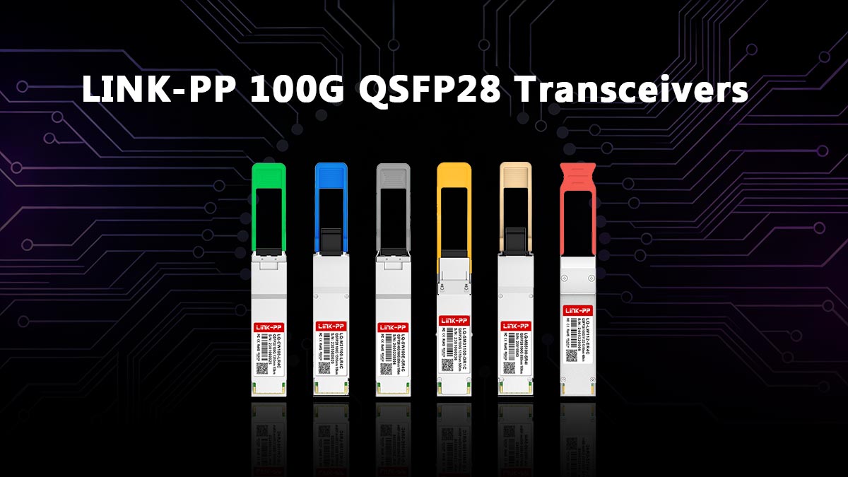
LINK-PP 100G QSFP28 modules are engineered for:
-
High-density 100G Ethernet connectivity in data centers and enterprise cores
-
Single-mode and multi-mode fiber support with multiple optical formats (LR4, CWDM4, ER4, ZR4)
-
Wide compatibility with major switching platforms from Cisco, Arista, Dell, Juniper, and other MSA-compliant systems
-
Real-time Digital Diagnostic Monitoring (DDM/DOM) and hot-pluggable operation for efficient maintenance and monitoring
You can explore the full range of LINK-PP 100G QSFP28 and SFP-DD transceivers—covering various distances, wavelengths, and industry standards—at the official product page.
Make Your Choice with Confidence
Selecting the right 100G QSFP28 transceiver is a critical step in future-proofing your network. To ensure optimal performance and long-term value:
-
Start with platform compatibility and optical requirements
-
Validate link budget and environmental constraints
-
Confirm vendor coding and firmware support
-
Factor in quality assurance, lead time, and warranty terms
If your time is valuable and you need an expert partner to support deployment, testing, or volume supply of 100G QSFP28 optics, consider leveraging LINK-PP’s engineering support and broad product portfolio to accelerate your network project with confidence.
?Appendix A: Reach & Wavelength Quick Chart (100G QSFP28)
| Module Type |
Optical Architecture |
Wavelength(s) |
Fiber Type |
Connector |
Typical Reach |
Common Use Case |
| SR4 |
Parallel optics (4×25G) |
850 nm |
MMF (OM3/OM4) |
MPO-12 |
70 m (OM3) / 100 m (OM4) |
Intra-rack / row, data centers |
| PSM4 |
Parallel optics (4×25G) |
1310 nm ×4 |
SMF |
MPO-12 |
500 m–2 km |
Campus / DC short SMF links |
| CWDM4 |
WDM (4×25G) |
~1271–1331 nm |
SMF |
Duplex LC |
2 km |
Cost-optimized DC interconnect |
| LR4 |
WDM (4×25G) |
~1295–1310 nm |
SMF |
Duplex LC |
10 km |
DC interconnect, metro edge |
| ER4 |
WDM (4×25G) |
~1295–1310 nm |
SMF |
Duplex LC |
40 km |
Metro / regional networks |
| ZR4 |
WDM (4×25G) |
~1295–1310 nm |
SMF |
Duplex LC |
80 km |
Long-haul / DCI |
| eZR4+ |
Enhanced WDM |
~1295–1310 nm |
SMF |
Duplex LC |
80–100 km* |
Extended-reach DCI |
| BiDi |
Bi-directional (2λ) |
~850/900 nm or 1270/1330 nm |
MMF or SMF |
Duplex LC |
100–500 m |
Fiber-limited environments |
| DR1 / FR1 / LR1 |
Single-lambda (100G PAM4) |
1310 nm |
SMF |
Duplex LC |
500 m / 2 km / 10 km |
Next-gen 100G, lower power |
*Actual reach depends on link budget, FEC, and fiber quality.
?Appendix B: Glossary of Key Terms
▶ QSFP28
Quad Small Form-factor Pluggable 28. A compact optical module supporting up to 4 × 25 Gbps lanes for 100G Ethernet.
▶ NRZ (Non-Return-to-Zero)
A modulation format encoding 1 bit per symbol using two signal levels. Provides better noise tolerance and simpler link budgets than PAM4.
▶ PAM4 (Pulse Amplitude Modulation, 4-level)
Encodes 2 bits per symbol using four signal levels, doubling data rate at the cost of reduced noise margin and higher SNR requirements.
▶ SNR (Signal-to-Noise Ratio)
A measure of signal quality. Higher SNR improves BER performance; PAM4 systems require significantly higher SNR than NRZ.
▶ Link Budget
The total allowable optical loss in a link, calculated from transmitter power, receiver sensitivity, fiber attenuation, and connector/splice losses.
▶ FEC (Forward Error Correction)
A digital signal processing technique that detects and corrects bit errors, improving BER and extending effective reach—especially critical for PAM4 links.
▶ DDM / DOM (Digital Diagnostic Monitoring)
A feature allowing real-time monitoring of module temperature, voltage, laser bias current, and TX/RX optical power via I²C.
▶ WDM (Wavelength Division Multiplexing)
A technique that transmits multiple data channels on different wavelengths over a single fiber pair (e.g., LR4, CWDM4).
▶ Parallel Optics
An optical architecture using multiple fibers and lanes in parallel (e.g., SR4, PSM4) to achieve high aggregate bandwidth.
▶ Hot-Pluggable
The ability to insert or remove a transceiver module without powering down the host system.
▶ MPO Connector
A multi-fiber push-on connector commonly used for parallel optics modules like SR4 and PSM4.
▶ MSA (Multi-Source Agreement)
Industry standards that define form factors, electrical interfaces, and management specifications to ensure multi-vendor interoperability.


