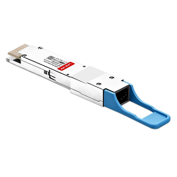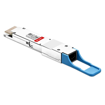
Are you struggling to upgrade your data center to 400G without replacing your existing 100G infrastructure? Integrating high-speed optics like the Arista QDD-400G-XDR4 transceiver offers a smart, cost-effective way to bridge this bandwidth gap seamlessly. By utilizing optical breakout capabilities, network engineers can easily scale throughput while maximizing the lifespan of legacy equipment.
How can a single 400G-XDR4 optical port communicate so effortlessly with four separate 100G-FR1 nodes? The secret lies in single-lambda PAM4 signaling, which aligns channel wavelengths and dramatically simplifies physical cabling across your racks. Mastering this interoperability allows you to build a flexible, future-proof network without the massive friction of a complete hardware overhaul.
✨ What is the Arista QDD-400G-XDR4 Transceiver?
Modern data centers demand high-density optics capable of scaling bandwidth without multiplying hardware footprint or power draw. The Arista QDD-400G-XDR4 optical module serves as a pivotal bridge between high-speed 400G switch fabrics and existing 100G infrastructure. Examining its internal optical engine and architectural specifications reveals why it has become an essential component in high-performance enterprise and cloud networks.

Core Specifications and Optical Features
The QDD-400G-XDR4 leverages the QSFP-DD (Quad Small Form-factor Pluggable Double Density) form factor, incorporating an eight-lane electrical interface that negotiates 50Gbps PAM4 per lane on the host side. On the optical side, the transceiver converts these electrical inputs into four parallel optical channels operating at 100Gbps each over separate fiber lanes, utilizing an MPO-12/APC connector interface over single-mode fiber.
Key technical characteristics defining this optical engine include:
- Operating Wavelength: Standardized at 1310nm single center wavelength across all four parallel lanes.
- Transmission Reach: Engineered for extended reach up to 2km, outperforming standard 500m 400GBASE-DR4 modules.
- Optical Connector Type: MPO-12/APC receptacle utilizing an 8-fiber active layout with angled physical contact to minimize back-reflection.
- Thermal and Power Profile: Typical power consumption under 10W, optimizing thermal management in dense switch layouts.
Single-Lambda 100G and PAM4 Signaling
Legacy 100G optics relied on four separate 25Gbps NRZ channels operating across multiple wavelengths on a single fiber pair. The QDD-400G-XDR4 adopts single-lambda 100G technology, where each of the four optical transmitters independently generates a full 100Gbps stream on a single wavelength over its dedicated fiber lane. Eliminating optical multiplexers drastically lowers component count, improves mean time between failures (MTBF), and reduces insertion loss across the optical path.
Achieving this 100Gbps single-lambda throughput requires Four-Level Pulse Amplitude Modulation (PAM4) combined with a Digital Signal Processor (DSP). Unlike traditional Non-Return-to-Zero (NRZ) signaling that transmits one bit per cycle using two voltage levels, PAM4 uses four distinct signal levels (00, 01, 10, 11) to encode two bits per symbol. The integrated DSP compensates for chromatic dispersion, signal distortion, and optical attenuation, maintaining low Bit Error Rates (BER) over the extended 2km reach of the QDD-400G-XDR4.
Physical Architecture and Real-World Deployment Scenarios
The physical architecture of the QDD-400G-XDR4 integrates an internal gearbox DSP that translates the 8x50Gbps PAM4 host electrical signal into 4x100Gbps PAM4 optical channels. This internal 8-to-4 electrical-to-optical conversion enables native 4x100G breakout capabilities without requiring external conversion hardware inside the switch chassis.
Network architects deploy this flexible architecture across several core infrastructure scenarios:
- High-Density Spine-to-Leaf Aggregation: Enables a 32-port 400G spine switch to directly connect to 128 individual 100G leaf switch ports, quadrupling switch port density.
- Gradual 400G Core Migration: Facilitates incremental core upgrades by attaching new 400G switches directly to active legacy 100G aggregation nodes.
- Cross-Building Campus Uplinks: Provides 2km transmission distance to link separate data center facilities or server halls without needing costly optical amplification.
- Structured Cabling Optimization: Simplifies patch panel runs by consolidating four discrete 100G links into a single MPO trunk cable.
✨ Understanding 100G-FR1 for QDD-400G-XDR4 Connections
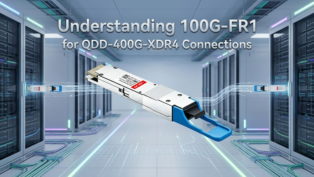
Connecting a high-density 400G switch port directly to distinct 100G endpoint nodes relies on precise optical compatibility across both ends of the link. The 100GBASE-FR1 specification plays a crucial role in these breakout architectures by defining the optical receiver and transmitter parameters required for single-lambda operation. Aligning these standards ensures seamless data transmission without introducing latency or optical power mismatches.
Key Features of 100GBASE-FR1 Optics
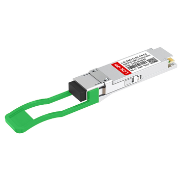
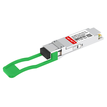
The 100GBASE-FR1 optical standard, formalized by the 100G Lambda MSA, defines a single-channel 100Gbps specification designed for medium-reach data center applications. By leveraging 53GBaud PAM4 modulation on a single optical wavelength, FR1 modules eliminate the need for multi-wavelength multiplexing found in older 100G optics. This streamlined architecture significantly reduces transceiver power consumption while maintaining lower latency and high transmission integrity.
Additionally, 100G-FR1 transceivers incorporate host-side Forward Error Correction (RS-FEC 544,514) to maintain acceptable Bit Error Rates (BER) over standard single-mode fiber links. The optical engine utilizes Electro-absorption Modulated Lasers (EML) to ensure stable signal propagation across variable temperature ranges. These unified electrical and optical profiles allow 100G-FR1 endpoints to cleanly decode incoming signals originating from a split QDD-400G-XDR4 host port.
Wavelength and Fiber Type Requirements
Physical layer compatibility between 400G breakout ports and distant 100G nodes depends strictly on matching optical wavelengths and media types. 100GBASE-FR1 optics operate at a center wavelength of 1310nm (specifically spanning the 1304.5nm to 1317.5nm range) over OS2 single-mode fiber (SMF). Because the QDD-400G-XDR4 emits four parallel channels on this exact 1310nm wavelength, the optical signals map directly across the fiber strands without spectral skew.
Deploying these optics requires standard SMF cabling paired with LC duplex connectors at the 100G-FR1 node and MPO-12/APC connectors at the 400G end. The Angled Physical Contact (APC) polish on the MPO interface is vital for preventing back-reflection (optical return loss) into the QDD-400G-XDR4 lasers, which could otherwise degrade the PAM4 signal quality. Consistent adherence to OS2 single-mode specifications ensures low attenuation rates (typically 0.35dB/km at 1310nm) across all channel paths.
Reach Differences: 2km FR1 vs 500m DR1
While 100GBASE-DR1 and 100GBASE-FR1 both utilize single-lambda 100G PAM4 modulation, their primary distinction lies in maximum transmission distance and optical attenuation allowance. Standard DR1 optics are strictly designed for short intra-rack links up to 500m, whereas FR1 extends link reach up to 2km across large data center campuses.
Evaluating these reach capabilities highlights why transmission distance directly dictates optical module selection for breakout topologies.
| Feature / Capability | 100GBASE-DR1 | 100GBASE-FR1 |
| Maximum Transmission Reach | Up to 500m | Up to 2km |
| Primary Deployment Scope | Intra-rack and adjacent-rack server connections | Cross-row, campus-wide, and inter-building uplinks |
| Optical Insertion Loss Budget | Limited (typically up to 3.0dB) | Extended (typically up to 4.0dB) |
| Patch Panel Tolerance | Low tolerance for multiple optical connectors | Higher tolerance for complex structured patch runs |
| Breakout Matching Partner | Pairs with standard 400G-DR4 optics | Pairs directly with QDD-400G-XDR4 optics |
Because 100G-FR1 offers an expanded loss budget and four times the physical distance of DR1, it matches the extended 2km reach specs of the QDD-400G-XDR4 without creating optical power bottlenecks. This distance alignment establishes a solid foundation for linking distant switch tiers without signal degradation.
Why 100G-FR1 Pairs Perfectly with 400G-XDR4
Building on this 2km distance capability, the QDD-400G-XDR4 transceiver is specifically engineered as an extended-reach 4x100G breakout module that mirrors 100G-FR1 optical specifications lane-for-lane. Standard 400G-DR4 modules are restricted to a 500m reach, making them unable to link with 100G-FR1 nodes located further across a facility. The XDR4 variant delivers the higher optical power budget required to cover spans up to 2km seamlessly.
Furthermore, both 100G-FR1 and individual lanes of the QDD-400G-XDR4 operate on identical signaling parameters, including 53 GBaud PAM4 rates, RS-FEC schemes, and 1310nm wavelengths. This complete physical and optical parity guarantees that each broken-out lane acts as a native 100GBASE-FR1 interface without requiring optical attenuators. As a result, network operators achieve a reliable, plug-and-play breakout solution for high-density 400G-to-100G deployments across the data center.
✨ How QDD-400G-XDR4 Breakout Connections Work
Breakout architectures allow network operators to maximize switch port density by dividing a single high-speed physical interface into multiple lower-speed logical links. Understanding the optical and electrical mechanics of this conversion is vital for establishing reliable connectivity between 400G core switches and 100G edge devices. Proper cabling choices, optical power budget calculations, and switch configurations ensure every broken-out channel operates without packet loss.
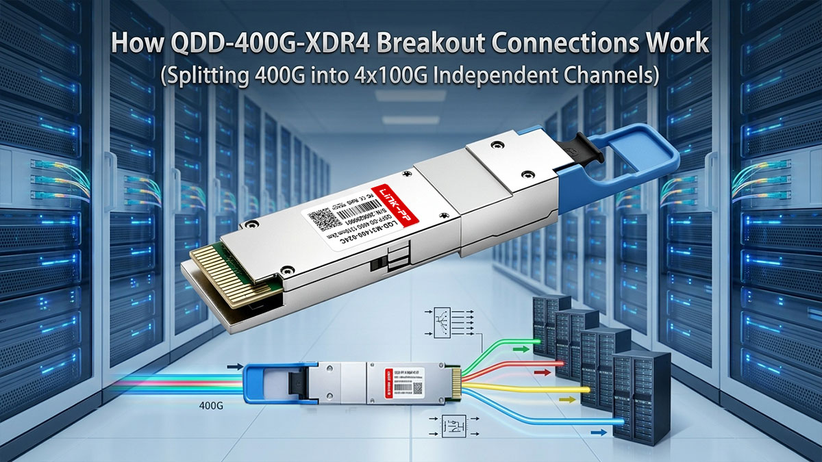
Splitting 400G into 4x100G Independent Channels
The internal gearbox of the QDD-400G-XDR4 optical transceiver converts an eight-lane 50Gbps PAM4 host electrical interface into four parallel 100Gbps optical channels. Each of these four optical transmitters fires at an independent 100Gbps PAM4 rate over a dedicated single-mode fiber pair, allowing the single physical port to act as four standalone interfaces.
From a logical standpoint, the host switch assigns each broken-out channel its own interface index and independent traffic statistics counters. While physical fiber optical signals are completely isolated to eliminate channel crosstalk, operators should note that all four lanes share common module hardware, such as the internal DSP and power circuitry.
Optical Cabling: MPO-12/APC to LC Breakout Patch Cables
Physical breakout connectivity relies on an MPO-12/APC female connector at the QDD-400G-XDR4 end, splitting into four distinct duplex LC connectors at the 100G-FR1 destination nodes. The MPO-12/APC interface uses eight active fiber strands (four transmit and four receive) with a standard 8-degree angled polish to minimize optical return loss and back-reflection.
Using standard flat-polished MPO/UPC connectors instead of angled MPO/APC connectors causes severe optical return loss that degrades PAM4 signal quality and disrupts communication. Proper channel alignment requires Type-B cross-over cable polarity, ensuring that the transmit (Tx) fiber from each QDD-400G-XDR4 optical lane connects cleanly to the receive (Rx) port of its corresponding 100G-FR1 transceiver.
Calculating Optical Power Budgets and Insertion Loss Margin
Establishing a robust optical link requires evaluating the total insertion loss margin between the QDD-400G-XDR4 transmitter and the 100G-FR1 receiver across the entire channel path. The maximum allowable insertion loss budget for a 2km 100GBASE-FR1 link is typically around 4.0dB, accounting for fiber attenuation at 1310nm (approximately 0.35dB/km) and connector loss.
Engineers must tally all signal loss sources — including MPO transitions, LC patch panel connections, and fiber splices — to prevent optical power from dropping below receiver sensitivity thresholds. Because the QDD-400G-XDR4 outputs higher optical launch power than standard 500m DR4 modules, it maintains adequate signal margin across complex structured cabling runs.
Configuring 4x100G Breakout Ports on Arista EOS
Operating the QDD-400G-XDR4 module in breakout mode requires explicit command-line configuration on the Arista EOS operating system to reassign switch port hardware resources. Network administrators execute the split 4x100 command under the physical interface context to map the single 400G port into four logical sub-interfaces.
Once the split command is applied, Arista EOS re-allocates internal SerDes lanes and generates four distinct sub-interfaces (such as Ethernet1/1/1 through Ethernet1/1/4). Under each newly generated sub-interface, administrators must execute speed forced 100gfull and enable Reed-Solomon FEC via fec rs (or fec auto) to finalize stable link status with connected 100G-FR1 nodes.
✨ Compatibility Rules for QDD-400G-XDR4 to 100G-FR1 Interoperability
Achieving stable physical and logical link states between high-density 400G hosts and 100G endpoints requires strict adherence to multi-layer alignment rules. Beyond basic physical connector coupling, network engineers must ensure precise synchronization across error correction modes, port parameters, fiber routing, and real-time optical power metrics. Following these compatibility guidelines eliminates subtle physical-layer faults and guarantees reliable packet processing across all broken-out channels.
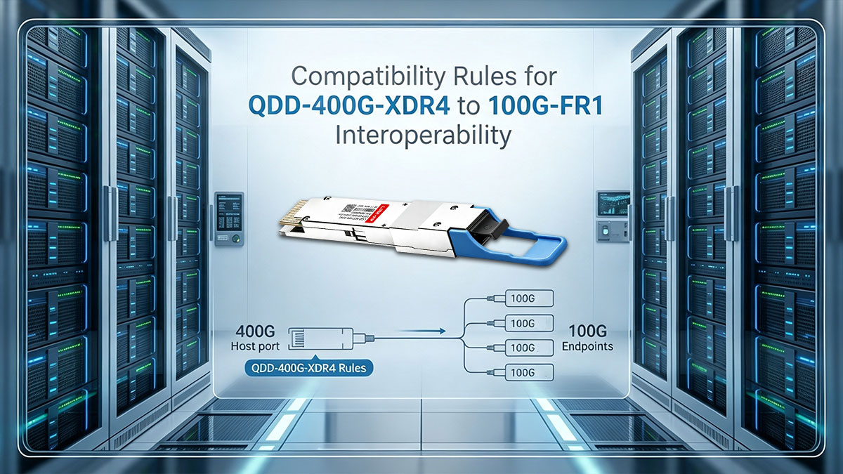
Matching RS-FEC Modes Across 400G and 100G Ends
Reed-Solomon Forward Error Correction (RS-FEC) is mandatory for 100G single-lambda PAM4 transmission to correct burst errors and maintain acceptable Bit Error Rates (BER). Both the broken-out channels of the QDD-400G-XDR4 and the remote 100G-FR1 optical modules must be configured to use matching RS(544,514) FEC modes, often designated as KP4 FEC.
If one end of the link defaults to Base-R (FC-FEC) or has FEC disabled entirely, the physical layer will fail to achieve alignment, leaving the port in an operational "down" state. Network administrators must explicitly verify that FEC settings on both switch interfaces match, as auto-negotiation for FEC across breakout topologies is frequently unsupported.
Port Speed Settings and Manual Breakout Setup
Auto-negotiation cannot reliably detect physical breakout topologies across mixed 400G and 100G optics. To establish link integrity, the 400G host switch port housing the QDD-400G-XDR4 module must be manually split using interface commands, followed by explicit speed forcing on each resulting sub-interface.
Similarly, the remote switch ports hosting the 100G-FR1 transceivers must be hardcoded to 100gfull rather than set to auto-sense modes. Eliminating speed and duplex auto-negotiation prevents mismatched link training sequences and ensures instant link bring-up upon fiber insertion.
Cable Polarity and Channel Mapping Guidelines
Proper fiber array mapping relies on standardized 8-fiber active MPO lane layouts and Type-B crossover polarity across the patch path. The QDD-400G-XDR4 transceiver routes its four 100G transmit (Tx) and four receive (Rx) signals over defined pin positions inside the MPO-12/APC receptacle, requiring a Type-B breakout assembly to invert transmit and receive fibers automatically before they reach each destination node.
Reversing cable polarity or confusing channel assignments results in dark fibers and link failures. Engineers should follow a systematic port-mapping layout during deployment:
- Connect MPO Tx Lane 1 to the Rx port of 100G-FR1 Node A.
- Connect MPO Tx Lane 2 to the Rx port of 100G-FR1 Node B.
- Connect MPO Tx Lane 3 to the Rx port of 100G-FR1 Node C.
- Connect MPO Tx Lane 4 to the Rx port of 100G-FR1 Node D.
Checking Link Health via DOM Metrics
Digital Optical Monitoring (DOM) provides real-time diagnostic visibility into the health and operating parameters of each optical channel. Monitoring these metrics allows network administrators to proactively identify physical layer degradation before complete link failure occurs.
Key DOM parameters to monitor on both the QDD-400G-XDR4 host port and connected 100G-FR1 nodes include:
- TX Optical Power: Ensures laser drivers are launching signals within normal operating ranges.
- RX Optical Power: Confirms received light falls between sensitivity thresholds and saturation limits.
- Operating Temperature: Detects thermal buildup that could cause laser wavelength drift.
- Laser Bias Current: Identifies transmitter component degradation over time.
✨ Troubleshooting Common QDD-400G-XDR4 Interop Issues
Deploying high-density optical breakouts occasionally introduces physical and configuration hurdles that prevent links from reaching an operational "up" state. Systematically isolating faults across physical cabling, optical power thresholds, and host software configurations ensures rapid link restoration. Following structured diagnostic workflows allows network administrators to maintain optimal throughput across all broken-out channels.

Resolving Partial Breakout Link Failures
A partial breakout failure occurs when one or two 100G channels remain operational while adjacent lanes on the same QDD-400G-XDR4 port fail to establish link. This symptom typically points to localized optical path issues or pin-specific physical damage rather than complete module failure.
To resolve single-lane drops across a broken-out port, engineers should execute the following targeted troubleshooting steps:
- Inspect specific MPO ferrule pin positions for dust or oil contamination using a fiber scope.
- Clean affected MPO-12/APC connector ends using dedicated dry-cloth cassette cleaners.
- Test individual LC duplex patch cords connected to offline 100G-FR1 nodes.
- Swap the suspect breakout leg to a known-good 100G-FR1 port to isolate transceiver hardware faults.
Fixing RX Optical Power Overload and Loss Issues
Optical power anomalies happen when received light falls outside the specified receiver sensitivity range, resulting in high Bit Error Rates (BER) or total loss of signal. Excessive attenuation causes Rx optical loss, whereas short patch runs paired with high-power transmitters can cause optical overload.
Diagnosing and correcting power level imbalances requires a systematic measurement approach:
- Verify current Rx optical power levels via Digital Optical Monitoring (show interfaces phy detail in Arista EOS).
- Clean all intermediate LC and MPO patch panel adapter bulkheads to reduce insertion loss.
- Install in-line optical attenuators (typically 2dB to 5dB) if Rx power exceeds the maximum input threshold.
- Replace damaged single-mode patch cables showing excessive bend radius stress or micro-bends.
Correcting Mismatched FEC Configurations
Forward Error Correction mismatches represent one of the most frequent software configuration errors in single-lambda 100G PAM4 deployments. When the host port of a QDD-400G-XDR4 channel and a remote 100G-FR1 node operate with conflicting FEC algorithms, physical alignment fails or results in high FEC uncorrectable error rates.
Administrators can align FEC parameters and restore link state by applying these CLI corrective actions:
- Check current FEC status on both switch ends using show interfaces EthernetX/Y/Z status.
- Explicitly configure Reed-Solomon FEC (fec mode rs or fec rs) on all sub-interfaces rather than non-standard modes.
- Disable auto-negotiation on 100G-FR1 endpoints to enforce static FEC mode selection.
- Verify that host SerDes settings match the mandatory IEEE 802.3 RS(544,514) / KP4 FEC framing standard.
✨ Network Design Based on QDD-400G-XDR4 Optical Transceiver
Modern network architectures leverage breakout optics to scale capacity without incurring massive hardware replacement costs. Strategic deployment of the QDD-400G-XDR4 optical module enables architects to transition core and distribution layers to 400G while preserving operational stability across existing infrastructure. Integrating these flexible optical links simplifies cabling layouts, increases switch port efficiency, and streamlines migration roadmaps across diverse enterprise environments.
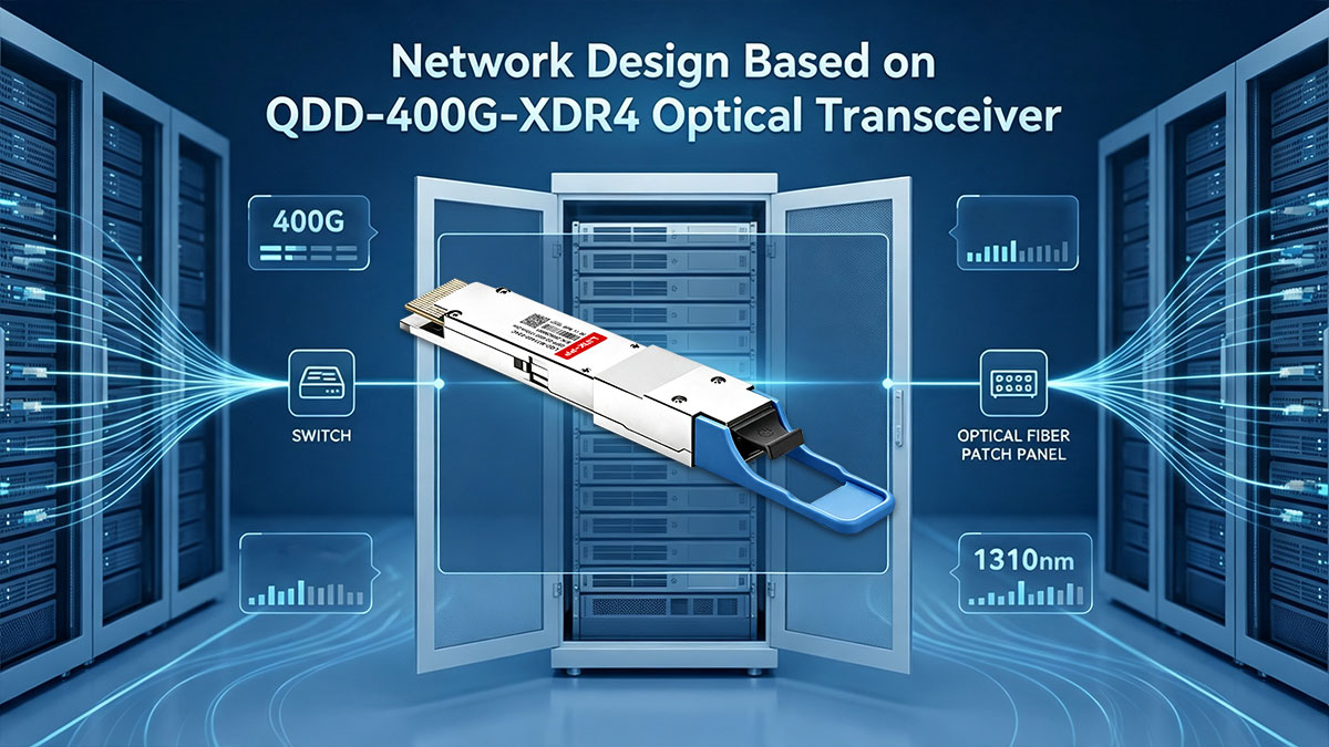
Upgrading 100G Spine-Leaf Architecture to 400G
Upgrading a traditional spine-leaf fabric to 400G often presents a challenge when leaf switches still rely on 100G uplinks. Deploying the QDD-400G-XDR4 on high-density 400G spine switches allows each spine port to fan out to four separate 100G leaf switches using 100G-FR1 optics.
This breakout topology quadruples the effective port density of the spine layer without requiring a simultaneous hardware refresh of every leaf switch. Network operators achieve an incremental, pay-as-you-grow upgrade strategy while optimizing overall rack space and power distribution.
Connecting 400G Core Switches with Legacy 100G Aggregation Nodes
Interfacing next-generation 400G core switches with legacy 100G aggregation layer switches requires a reliable, direct optical transition. The QDD-400G-XDR4 module bridges this generational gap by presenting four independent 100G interfaces to legacy aggregation nodes without requiring intermediate optical transponders.
Because each channel operates as a native 100GBASE-FR1 link, legacy switches receive clean, standardized single-lambda 100G signals. This direct interconnectivity reduces latency, eliminates extra conversion hardware, and protects historical investments in existing aggregation platforms.
Building High-Speed Inter-Rack and Cross-Building Uplinks
Data center facilities often require uplinks that extend beyond the standard 500-meter reach of intra-rack DR4 optics. Offering a transmission distance up to 2km, the QDD-400G-XDR4 transceiver provides the extended reach necessary for campus-wide links and inter-rack connections across separate halls.
By utilizing structured single-mode fiber trunking with MPO-to-LC breakouts, operators can run consolidated high-capacity links between distant buildings. The combination of extended 2km reach and high optical power budgets ensures resilient signal delivery across complex patch panel routes.
✨ Evaluating Compatible Alternatives to Arista QDD-400G-XDR4
High-density optical deployments often encounter budget constraints when relying strictly on OEM-branded hardware. Evaluating third-party QDD-400G-XDR4 compatible optical modules offers network managers a cost-effective strategy to expand bandwidth without compromising link performance. Choosing high-quality, MSA-compliant alternatives ensures reliable integration into existing 400G-to-100G breakout infrastructures.
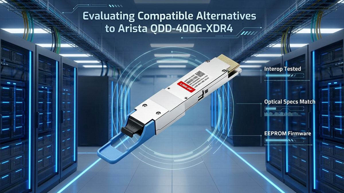
Lowering Optics Costs Without Sacrificing Performance
Optical transceivers represent a substantial share of total budget allocations during high-density 400G network upgrades. Choosing reliable third-party alternatives to the Arista QDD-400G-XDR4 allows organizations to drastically lower per-port expenses while retaining matching optical power budgets and 2km transmission capabilities.
These cost savings are achieved without degrading signal integrity, as compatible optics utilize high-grade 1310nm optical components paired with advanced PAM4 signal processors. Redirecting saved capital enables engineering teams to deploy additional backup links or expand overall rack density.
Ensuring Signal Integrity and High-Standard Testing
Establishing stable physical layer links across 400G breakout topologies requires strict hardware quality control and performance compliance. Quality compatible modules engineered as alternatives to the QDD-400G-XDR4 strictly follow IEEE and MSA standards to guarantee matching optical power levels and receiver sensitivity.
To ensure consistent performance and prevent packet drops over 2km fiber spans, reliable optical transceiver suppliers put every module through practical factory testing before shipment:
- Optical Spectrum Test: Verifies that the 1310nm laser stays within its required central wavelength.
- Eye Pattern Test: Measures signal clarity to ensure clean PAM4 waveforms with low jitter.
- Bit Error Rate Test (BERT): Tests full line-rate traffic to confirm data passes through without frame errors.
- Temperature Test: Evaluates performance under fluctuating thermal conditions to prevent optical drift in real-world switch environments.
Seamless EEPROM Coding and DOM Diagnostics Support
Hardware recognition on Arista switch platforms depends on precise memory map programming within the module. Fully compatible QDD-400G-XDR4 alternatives rely on proper EEPROM coding, preventing host switches from triggering "unsupported transceiver" warnings or disabling interface ports.
Accurate EEPROM coding also enables native Digital Optical Monitoring (DOM) support within Arista EOS environments. Network engineers can view complete real-time diagnostic telemetry — including per-lane Tx optical output power, Rx optical input power, laser bias current, module supply voltage, and operating temperature — with the same visibility provided by OEM optics.
High-Reliability Deployment with QDD-400G-XDR4 Compatible Module
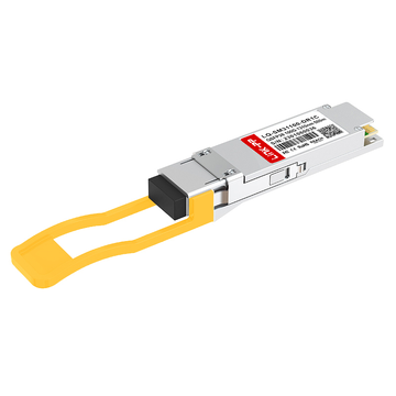
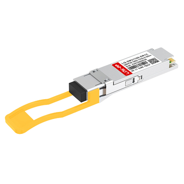
For network operators seeking a proven third-party alternative to the Arista QDD-400G-XDR4, the LINK-PP LQD-M31400-024C 400GBASE-XDR4 module provides an enterprise-grade, MSA-compliant option. Engineered to mirror the electro-optical performance of the OEM transceiver, it ensures seamless interoperability when breaking out into remote 100G-FR1 endpoints over single-mode fiber.
LINK-PP subjects each module to strict host-platform validation to guarantee long-term link stability in high-density switch environments. Key technical features and deployment advantages of the LINK-PP LQD-M31400-024C optical module include:
- Full IEEE & MSA Standard Compliance: Fully adheres to 100G Lambda MSA specifications and IEEE 802.3cu protocols for reliable 4x100G breakout framing.
- Matched 2km Optical Reach: Utilizes four parallel 1310nm PAM4 lanes over an MPO-12/APC SMF interface to deliver strong link margins across extended campus runs.
- Native Arista EOS Recognition: Pre-programmed CMIS-compliant EEPROM firmware prevents "unsupported transceiver" port security alarms while enabling full DOM telemetry visibility.
- Optimized Power Consumption: Features an efficient DSP thermal design (typically under 10W) to maintain low operating temperatures inside crowded switch chassis layouts.
✨ Conclusion: Key Takeaways for Deploying QDD-400G-XDR4 Interoperability
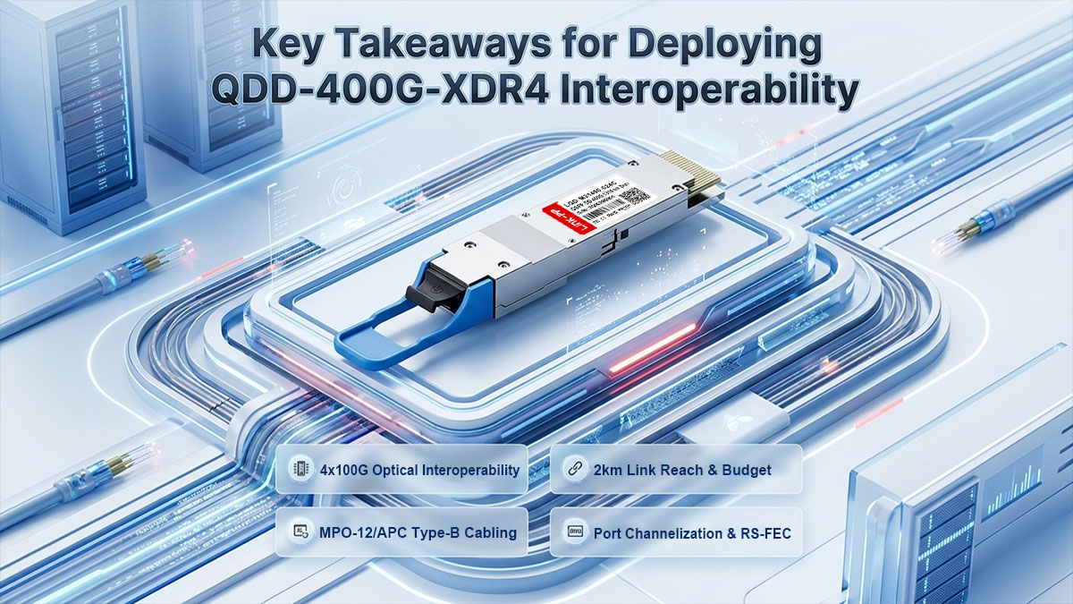
Integrating 400G switch fabrics with legacy 100G endpoints offers a practical, high-density architecture for expanding modern data center bandwidth. Deploying the QDD-400G-XDR4 transceiver enables seamless 4x100G breakouts to remote 100G-FR1 nodes, extending link distances up to 2km while protecting existing hardware investments. Achieving stable link alignment across this topology requires strict adherence to physical layer standards, including MPO-12/APC Type-B crossover cabling, explicit Arista EOS port channelization, and matching RS(544,514) FEC configurations.
Choosing high-quality, MSA-compliant optical modules allows engineering teams to scale network density while keeping optics budgets manageable. Fully tested third-party alternatives deliver complete EEPROM firmware recognition and real-time DOM diagnostic visibility, ensuring the same operational stability as OEM hardware. Whether you are upgrading spine-leaf architectures or establishing cross-building uplinks, you can find fully tested QDD-400G-XDR4 compatible optics and matching 100G-FR1 breakout modules directly through the LINK-PP Official Store.