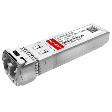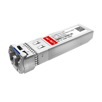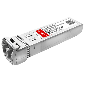
10Gtek AXS85 192 M3 optical transceiver is widely deployed in enterprise and data center networks requiring high-speed optical connectivity. As bandwidth demands continue to grow, maintaining stable optical links and ensuring interoperability between modules and host devices has become a critical part of modern network design and operation.
This makes optical compatibility validation an essential step in deployment planning. Even if a transceiver matches required specifications, issues such as vendor coding, firmware restrictions, or fiber mismatches can still impact performance. Proper validation ensures stable link establishment, reduces downtime risk, and supports consistent operation across mixed vendor environments.
This article outlines the core elements needed to validate optical compatibility for the 10Gtek AXS85 192 M3:
- specifications and supported standards
- compatibility across switches and routers
- validation testing and diagnostic tools
- common issues and troubleshooting
- best practices for deployment
Together, these sections provide a practical framework for understanding and verifying optical behavior in real network environments.
🔯 Understanding the 10Gtek AXS85 192 M3
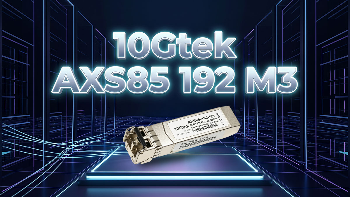
The 10Gtek AXS85 192 M3 is a 10GBASE-SR SFP+ optical transceiver designed for short-reach multimode fiber links in high-speed Ethernet networks. It operates at a fixed 850nm wavelength and supports up to 10Gbps data transmission over distances of up to 300 meters on OM3 multimode fiber, making it a standard solution for short-range data center and enterprise optical connectivity.
This module is specifically aligned with IEEE 802.3ae 10GBASE-SR standards and is optimized for duplex LC interface deployment. Its primary role is to provide stable short-distance optical transmission between switches, routers, and servers in high-density networking environments where low latency and predictable optical performance are required.
Key Technical Specifications
The 10Gtek AXS85 192 M3 is defined by a set of fixed optical and electrical parameters that directly determine compatibility and performance. These specifications are essential for validating whether the module can operate correctly within a given network environment.
The core technical parameters are:
- Form factor: SFP+ hot-pluggable optical transceiver
- Interface type: Duplex LC connector
- Operating wavelength: 850nm VCSEL-based transmission
- Transmission distance: up to 300m over OM3 multimode fiber
- Data rate capability: up to 10.3Gbps (10GBASE-SR compliant)
To clarify how these specifications translate into real deployment conditions, the key parameters are summarized below:
| Parameter | Specification |
|---|---|
| Standard | 10GBASE-SR (IEEE 802.3ae) |
| Wavelength | 850nm |
| Data Rate | up to 10.3Gbps |
| Reach | up to 300m (OM3 MMF) |
| Connector | Duplex LC |
| Fiber Type | OM3 / OM4 multimode fiber |
These parameters define the optical budget, fiber compatibility, and link distance limits, which must all align with the connected switch or network device for stable operation.
Typical Deployment Scenarios
The 10GBASE-SR architecture of the 10Gtek AXS85 192 M3 makes it suitable for short-range, high-density networking environments where multimode fiber is already deployed. Its usage is generally centered around intra-site connectivity rather than long-haul transmission.
Common deployment scenarios include:
- Enterprise campus networks connecting multiple buildings or floors
- Data center interconnects between racks or top-of-rack switches
- Aggregation and access layer links in hierarchical network architectures
- Network upgrade projects transitioning from 1G to 10G infrastructure
In these environments, the 850nm multimode design allows cost-efficient fiber deployment while maintaining high throughput across limited distances. It is especially effective where existing OM3/OM4 fiber infrastructure is available.
Why Compatibility Matters for This Module
Even though the 10Gtek AXS85 192 M3 follows the 10GBASE-SR standard, optical compatibility still plays a decisive role in whether the module will function correctly in a given system. Compatibility is not only about speed and wavelength, but also about how the host device interprets and supports the transceiver.
The importance of compatibility can be summarized through several key operational impacts:
- Link stability depends on correct recognition of the 850nm SR optical profile by the host system
- Network performance is affected when fiber type (OM3/OM4) or link budget is not properly matched
- Vendor interoperability may influence whether the module is accepted without warnings or restrictions
- Long-term maintenance is simplified when the module operates consistently across firmware and hardware updates
When these factors are properly aligned, the module can deliver stable 10Gbps short-range optical connectivity with predictable behavior across enterprise and data center environments.
🔯 What Optical Compatibility Means in Networking
Optical compatibility in networking refers to the ability of an optical transceiver such as the 10Gtek AXS85 192 M3 (10GBASE-SR 850nm 300m SFP+) to function correctly within a host system and fiber infrastructure without triggering errors, link failures, or performance degradation. It is not only determined by optical parameters like wavelength and distance, but also by how the module is recognized, powered, and validated by the networking device.
Physical Compatibility
Physical compatibility defines whether the 10Gtek AXS85 192 M3 can be properly installed into a network device and correctly connected to the optical fiber infrastructure. Even when optical specifications match, physical mismatch will prevent proper operation.
The key elements include:
- Port and connector matching between SFP+ slot and duplex LC interface
- Form factor verification ensuring SFP+ compliance with host cage design
- Mechanical fit requirements including latch stability and insertion alignment
When these conditions are met, the module can be securely seated in the port and correctly aligned with fiber patch cables, ensuring stable optical coupling and preventing insertion loss caused by poor mechanical alignment.
Physical compatibility is the foundation layer, and without it, no electrical or optical communication can be established.
Electrical Compatibility
Electrical compatibility ensures that the 10Gtek AXS85 192 M3 can properly communicate with the host device at the hardware and power interface level. This layer determines whether the switch or router can initialize the module successfully.
Key considerations include:
- Host device communication requirements through SFP+ electrical interface signaling
- EEPROM interaction used for module identification and parameter exchange
- Power consumption considerations within SFP+ power budget limits
If electrical compatibility is not satisfied, the module may not be detected correctly or may be rejected by the system, even if it is physically installed. Proper EEPROM communication is especially critical, as it enables the host system to read module identity, capability, and operational parameters.
Protocol Compatibility
Protocol compatibility ensures that the 10Gtek AXS85 192 M3 can operate correctly within the Ethernet communication standards expected by the network infrastructure. For this module, compliance with 10GBASE-SR standards is essential for stable link establishment.
Key aspects include:
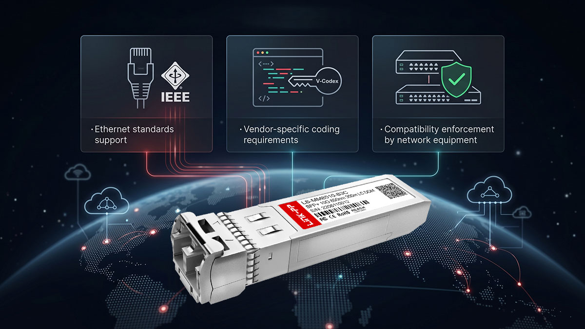
- Ethernet standards support based on IEEE 802.3ae 10GBASE-SR specification
- Link negotiation behavior between transceiver and switch interface logic
- Error handling mechanisms for maintaining link stability under signal variation
When protocol compatibility is properly aligned, the module can establish a stable 10Gbps link without negotiation failures or persistent error states. This layer ensures that both ends of the connection interpret and maintain the same communication rules.
Vendor Coding and Identification
Vendor coding and identification define how the 10Gtek AXS85 192 M3 is recognized by the host device firmware. Even if a module is fully standards-compliant, many networking platforms still rely on internal validation rules.
Key elements include:
- Role of EEPROM programming for storing module identity and capability data
- Vendor-specific coding requirements used by switch firmware for compatibility checks
- Compatibility enforcement by network equipment through acceptance or warning mechanisms
In many systems, incorrect or unrecognized coding may lead to warning messages or limited functionality, even when the optical link itself is technically functional. Proper identification ensures full system acceptance and enables full diagnostic visibility such as DOM monitoring.
When all four compatibility layers—physical, electrical, protocol, and vendor coding—are aligned, the 10Gtek AXS85 192 M3 can operate reliably within a 10GBASE-SR optical network environment with stable performance and predictable behavior.
🔯 Key Factors to Validate Before Deployment
Before deploying the 10Gtek AXS85 192 M3 in a live network, it is essential to validate several critical factors that directly influence optical compatibility and link stability. Proper validation ensures that the module will operate correctly within the intended switch platform, fiber infrastructure, and transmission distance requirements.
These checks are especially important in 10Gbps multimode environments, where even small mismatches in fiber type, power budget, or firmware support can lead to unstable links or complete link failure.
Switch and Router Compatibility
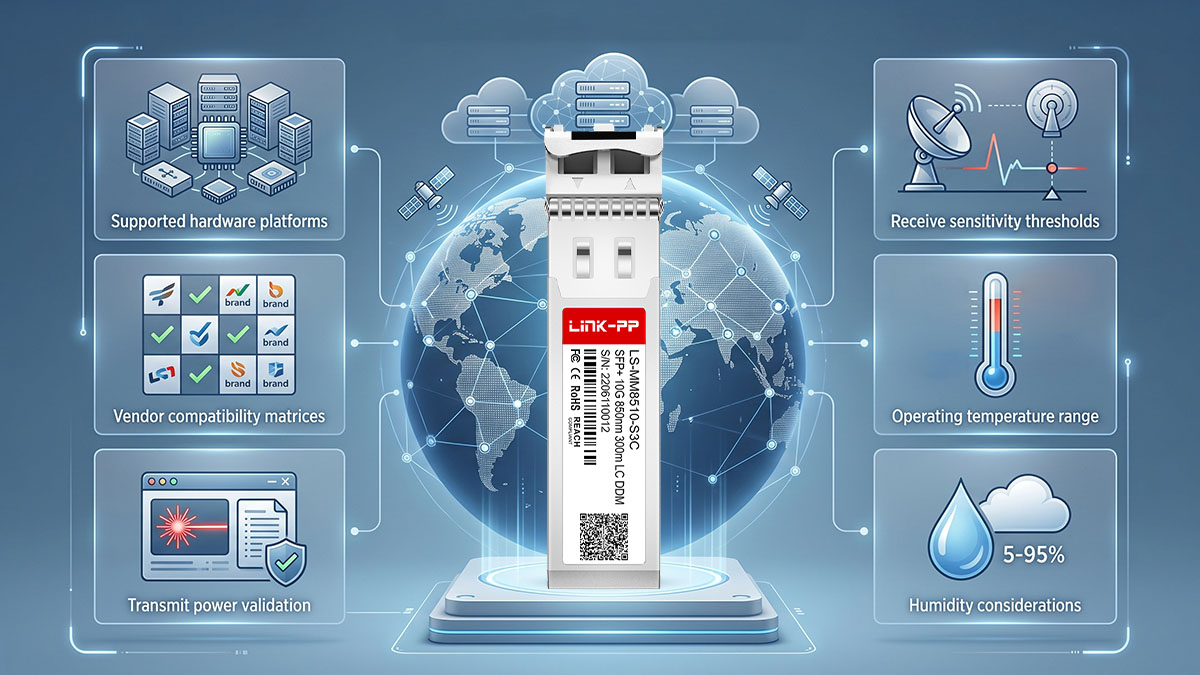
Switch and router compatibility defines whether the host device can correctly recognize and operate the 10Gtek AXS85 192 M3 module. Even when the module fully complies with the 10GBASE-SR standard, platform-level restrictions may still affect functionality.
Key validation points include:
- Verified support for SFP+ 10GBASE-SR modules on the target device
- Firmware version compatibility with third-party or non-vendor-coded optics
- Inclusion of the module type in the device’s compatibility or support matrix
- Proper detection of module parameters via system diagnostics
If the host device does not fully support the module, issues such as “unsupported transceiver” warnings or disabled ports may occur, even when physical and optical conditions are correct.
Fiber Infrastructure Verification
Fiber infrastructure plays a direct role in determining whether the 10Gtek AXS85 192 M3 can achieve stable 10Gbps transmission over the intended distance. Since this module operates at 850nm over multimode fiber, correct fiber selection is critical.
Important checks include:
- Use of OM3 or OM4 multimode fiber for optimal performance
- Verification of duplex LC patch cord compatibility
- Ensuring fiber cleanliness to minimize insertion loss
- Confirming total link distance does not exceed 300m (OM3) limit
Improper fiber type or contamination can significantly reduce optical signal quality, leading to packet loss or intermittent connectivity even within supported distances.
Optical Power Requirements
Optical power validation ensures that the transmitted and received signal levels remain within the operational range of the 10Gtek AXS85 192 M3 module. This is a key factor in maintaining stable 10Gbps links over multimode fiber.
Key considerations include:
- Transmit power levels must align with 850nm VCSEL output specifications
- Receive sensitivity must be sufficient for the full link distance
- Total link loss must remain within the optical budget for 10GBASE-SR
- Avoidance of excessive attenuation due to poor connectors or splicing
When optical power is not properly balanced, the link may appear operational but experience high error rates or intermittent failures under load.
Environmental Conditions
Environmental conditions influence the long-term stability and reliability of the 10Gtek AXS85 192 M3 in real-world deployments. While the module is designed for enterprise environments, operating conditions still affect performance consistency.
Key environmental factors include:
- Operating temperature range within vendor-defined limits
- Adequate airflow and thermal management inside network equipment
- Protection against dust and physical contamination of fiber connectors
- Stable power conditions within the host device chassis
Excessive heat or poor ventilation can reduce optical efficiency over time, while contaminated connectors can introduce unexpected signal loss.
🔯 How to Validate Optical Compatibility Step by Step
Validating optical compatibility for the 10Gtek AXS85 192 M3 requires a structured process that ensures the module will operate correctly across the switch platform, fiber infrastructure, and optical budget. A step-by-step validation approach helps eliminate configuration risks before deployment and ensures stable 10Gbps link performance in production environments.
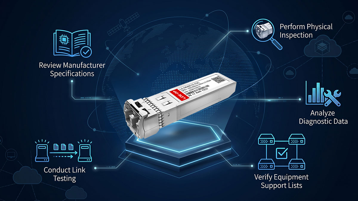
Each step focuses on a different layer of compatibility, from specification review to live link verification.
Review Manufacturer Specifications
The first step is to confirm that the 10Gtek AXS85 192 M3 matches the network’s technical requirements. This ensures baseline compatibility before any physical installation takes place.
Key actions include:
- Confirm 10GBASE-SR compliance for 10Gbps Ethernet operation
- Verify 850nm wavelength alignment with multimode fiber systems
- Check supported distance limit of up to 300m over OM3 fiber
- Ensure SFP+ form factor compatibility with host device ports
This step prevents mismatches between expected network design and actual module capabilities, especially in mixed-speed or multi-vendor environments.
Verify Equipment Support Lists
After confirming specifications, the next step is to validate whether the target switch or router officially supports the module or equivalent 10GBASE-SR optics.
Key checks include:
- Reviewing vendor compatibility or transceiver support matrices
- Confirming firmware version requirements for SFP+ modules
- Checking for any restrictions on third-party optical modules
- Ensuring platform supports DOM (Digital Optical Monitoring) features
This stage is critical because many network devices enforce strict optical validation rules, even for standards-compliant modules.
Perform Physical Inspection
Physical inspection ensures that the module and fiber infrastructure are correctly prepared for installation and operation.
Key validation points include:
- Confirm SFP+ slot and module alignment before insertion
- Inspect duplex LC connectors for dust or contamination
- Verify OM3/OM4 multimode fiber patch cords are in good condition
- Ensure proper cable routing to avoid bending or stress loss
Even minor physical issues can introduce insertion loss, signal degradation, or unstable link behavior once the module is active.
Conduct Link Testing
Link testing verifies whether the 10Gtek AXS85 192 M3 can successfully establish a stable 10Gbps optical connection under real operating conditions.
Key steps include:
- Insert module into SFP+ port and observe link status
- Confirm link up at 10Gbps speed on both ends of connection
- Perform connectivity tests such as ping or traffic forwarding
- Monitor for link flapping or intermittent disconnects
This step provides direct confirmation that physical, electrical, and protocol layers are functioning correctly together.
Analyze Diagnostic Data
The final step is to evaluate optical health using diagnostic tools such as DOM to ensure long-term stability and proper optical budget alignment.
Key metrics include:
- Transmit optical power levels at 850nm wavelength
- Receive signal strength across full link distance
- Module temperature and voltage stability
- Error counters and CRC statistics during traffic flow
Consistent and stable diagnostic readings indicate that the module is operating within its intended optical range and that the 300m OM3 link budget is properly maintained.
🔯 Common Compatibility Challenges and How to Resolve Them
Even when the 10Gtek AXS85 192 M3 is deployed in a standards-compliant environment, optical compatibility issues can still occur due to differences in switch firmware behavior, fiber conditions, or optical budget mismatches. Understanding these challenges and their root causes is essential for maintaining stable 10Gbps links in real-world networks.
Most issues fall into three categories: recognition problems, link establishment failures, and performance instability.
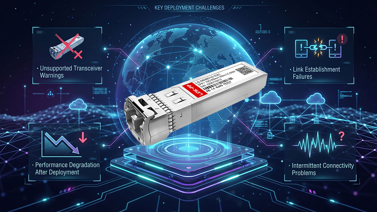
Unsupported Transceiver Warnings
An “unsupported transceiver” warning typically occurs when the host device does not fully recognize or approve the module at the firmware level, even if the module is technically compatible with 10GBASE-SR standards.
Common causes include:
- Strict vendor coding or EEPROM validation rules in switch firmware
- Lack of official inclusion in the device compatibility database
- Outdated network operating system or firmware version
- Platform restrictions on third-party optical modules
Resolution methods include:
- Updating switch firmware to the latest supported version
- Enabling broader transceiver compatibility settings (if supported)
- Verifying module identification data via system diagnostics
- Ensuring the device supports standard SFP+ 10GBASE-SR optics
In many cases, the optical link may still function, but system-level warnings can limit monitoring or administrative control.
Link Establishment Failures
Link establishment failures occur when the module is physically detected but fails to bring up a stable 10Gbps connection between endpoints.
Typical causes include:
- Mismatched fiber polarity in duplex LC connections
- Use of incorrect fiber type (e.g., OM2 instead of OM3/OM4)
- Exceeding the 300m transmission limit of 10GBASE-SR design
- Dirty or damaged fiber connectors introducing excessive loss
Resolution approaches include:
- Rechecking TX/RX polarity alignment on both ends
- Confirming OM3 or OM4 multimode fiber usage
- Reducing link distance or improving fiber quality
- Cleaning LC connectors and inspecting for physical damage
Once corrected, the link should stabilize and negotiate successfully at 10Gbps.
Intermittent Connectivity Problems
Intermittent connectivity is one of the most difficult issues to diagnose because the link may appear operational but experience random drops or instability under traffic load.
Common contributing factors include:
- Marginal optical power levels near receiver sensitivity limits
- Excessive insertion loss from patch panels or connectors
- Environmental interference such as heat or poor ventilation
- Aging or low-quality fiber infrastructure components
Resolution steps include:
- Measuring optical power using DOM or external optical power meters
- Replacing high-loss patch cables or connectors
- Improving rack airflow and thermal conditions
- Reducing total link complexity (fewer splices or connectors)
Stabilizing optical margin is key to eliminating intermittent behavior.
Performance Degradation After Deployment
Performance degradation occurs when the link remains up but experiences higher latency, packet loss, or increased error rates over time.
Typical causes include:
- Gradual optical signal degradation due to connector contamination
- Temperature drift affecting VCSEL output at 850nm wavelength
- Fiber bending or physical stress after installation
- Accumulated bit errors not immediately triggering link failure
Resolution methods include:
- Performing regular cleaning and inspection of LC connectors
- Monitoring DOM values for long-term trend changes
- Ensuring proper cable management and bend radius compliance
- Replacing degraded fiber segments in aging infrastructure
Long-term monitoring is especially important for maintaining stable 10Gbps performance in high-density environments.
🔯 Tools and Methods for Optical Compatibility Testing
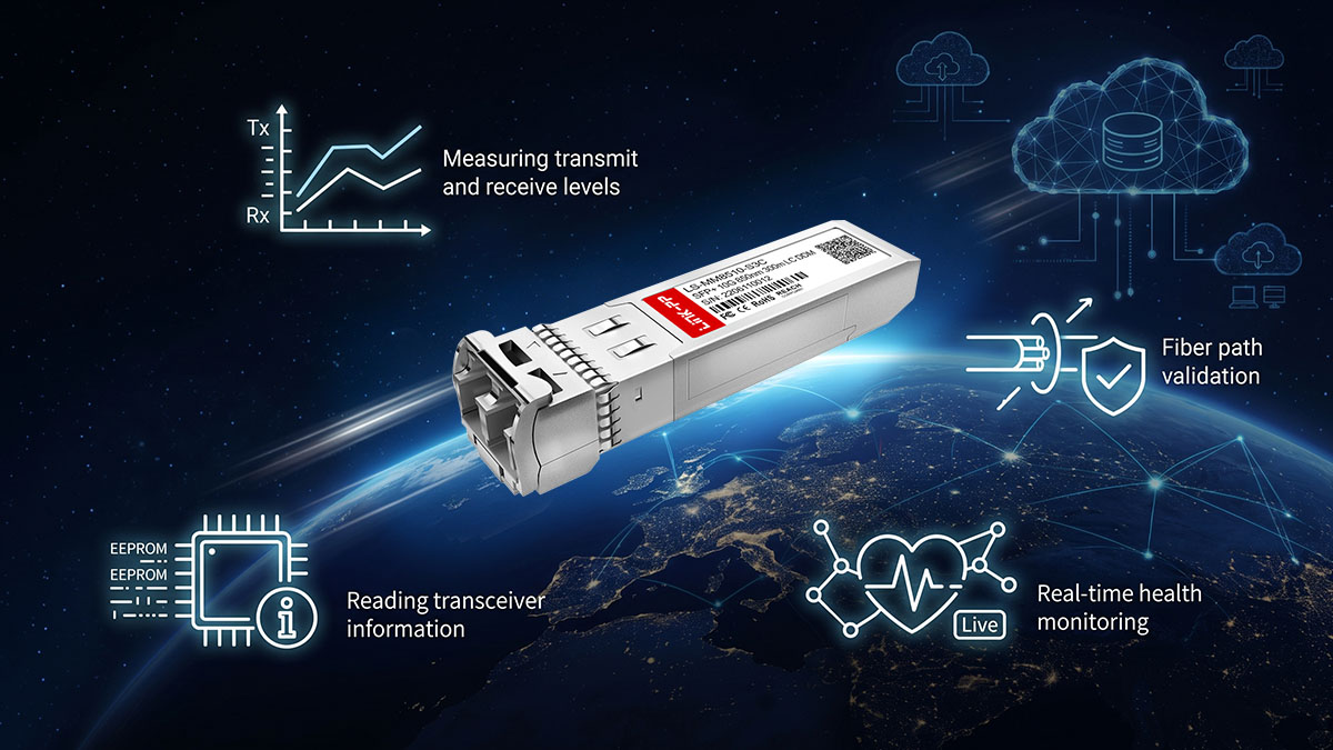
Testing optical compatibility for the 10Gtek AXS85 192 M3 requires both hardware instruments and built-in network diagnostics. These tools help verify whether the module is operating within its optical budget, correctly recognized by the host device, and stable under real traffic conditions.
Optical Power Meters
Optical power meters are used to measure the actual transmitted and received optical signal strength in a fiber link. This is one of the most direct ways to validate whether the 10Gtek AXS85 192 M3 is operating within its expected optical range.
Key usage points include:
- Measuring 850nm transmit power from the SFP+ module
- Checking receive power at the far end of the link
- Verifying total link loss against the 10GBASE-SR optical budget
- Identifying excessive attenuation caused by connectors or fiber defects
If power levels fall outside the acceptable range, the link may appear unstable or fail intermittently even if it initially comes up successfully.
Optical Time Domain Reflectometers (OTDR)
OTDR testing is used to analyze the entire fiber path and detect faults that are not visible through simple link checks. It is especially useful for longer multimode runs approaching the 300m limit of OM3 fiber.
Key functions include:
- Mapping fiber length and identifying total link distance
- Detecting splices, bends, or breaks along the fiber path
- Locating high-loss points in connectors or patch panels
- Verifying overall fiber quality before deploying 10Gbps links
For the 10Gtek AXS85 192 M3, OTDR results help confirm that the physical fiber infrastructure can support stable 10GBASE-SR transmission without hidden degradation points.
Network Diagnostic Commands
Most enterprise switches and routers provide built-in commands to verify optical module status and link behavior. These software-based tools are essential for real-time compatibility validation.
Typical checks include:
- Detecting whether the SFP+ module is recognized correctly
- Viewing interface status (up/down, speed negotiation results)
- Checking error counters such as CRC or frame drops
- Confirming 10Gbps link establishment on both ends
These diagnostics help quickly identify whether issues are related to optical hardware, configuration, or compatibility limitations.
Digital Optical Monitoring (DOM) Features
Digital Optical Monitoring (DOM) provides real-time performance data directly from the 10Gtek AXS85 192 M3 module. It is one of the most important tools for long-term compatibility validation.
Key monitored parameters include:
- Transmit and receive optical power at 850nm
- Module operating temperature
- Supply voltage stability inside the SFP+ module
- Bias current and laser performance indicators
DOM data allows network operators to detect early signs of degradation before a complete link failure occurs. For example, gradual power decline or rising temperature can indicate fiber contamination or environmental stress.
🔯 Comparing Compatibility Validation Approaches
Different optical compatibility validation approaches for the 10Gtek AXS85 192 M3 vary in depth, accuracy, and deployment stage applicability. Choosing the right method depends on whether the goal is pre-deployment assurance, real-time troubleshooting, or long-term operational stability. In practice, a combination of methods provides the most reliable validation outcome for 10Gbps multimode optical networks.
Laboratory Validation vs Production Validation
Laboratory validation is performed in a controlled environment before the 10Gtek AXS85 192 M3 is deployed in a live network, while production validation occurs after installation under real traffic conditions.
Key differences include:
- Laboratory testing focuses on controlled optical conditions and known-good hardware setups
- Production validation evaluates real-world variables such as traffic load and environmental factors
- Lab results provide repeatable baseline measurements, while production results reflect operational reality
- Troubleshooting is easier in lab environments due to reduced network complexity
A combined approach is typically preferred: laboratory validation confirms baseline compatibility, while production validation confirms real-world stability.
| Validation Type | Environment | Focus Area | Risk Level |
|---|---|---|---|
| Laboratory Validation | Controlled test setup | Specification compliance and baseline performance | Low |
| Production Validation | Live network environment | Real-world stability and interoperability | Higher |
This comparison highlights why lab testing alone is not sufficient for ensuring long-term optical reliability in 10GBASE-SR deployments.
Vendor Documentation vs Real-World Testing
Vendor documentation provides official specifications and compatibility guidance for the 10Gtek AXS85 192 M3, while real-world testing verifies how the module performs under actual network conditions.
Key distinctions include:
- Vendor documentation defines expected performance parameters such as 850nm wavelength and 300m reach
- Real-world testing validates how fiber quality, connectors, and switch behavior impact those specifications
- Official data ensures theoretical compatibility, while field testing confirms operational stability
- Documentation may not fully reflect firmware restrictions or platform-specific limitations
Key evaluation areas include:
- Confirming 10GBASE-SR support in vendor compatibility lists
- Testing module recognition across different switch models
- Verifying DOM readings under live traffic conditions
- Observing long-term stability beyond initial link establishment
When both sources align, confidence in deployment reliability increases significantly.
Reactive Troubleshooting vs Proactive Validation
Reactive troubleshooting occurs after compatibility problems appear in the network, while proactive validation is performed before deployment to prevent such issues.
Key differences include:
- Reactive troubleshooting addresses symptoms such as link failures or warnings after deployment
- Proactive validation identifies issues like fiber mismatch or firmware limitations in advance
- Reactive methods often involve downtime and service disruption
- Proactive methods reduce operational risk and improve deployment predictability
Key proactive validation practices include:
- Pre-checking fiber type compatibility (OM3/OM4 for 10GBASE-SR)
- Verifying switch firmware support for SFP+ modules
- Testing optical power margins before production rollout
- Simulating link conditions prior to full-scale deployment
Reactive approaches are still necessary for unexpected failures, but relying solely on them increases operational risk in high-speed optical environments.
🔯 Conclusion
The 10Gtek AXS85 192 M3 is a 10GBASE-SR 850nm 300m SFP+ optical transceiver that delivers reliable short-reach connectivity when optical compatibility is properly validated across hardware, fiber infrastructure, and system-level recognition. In real deployments, ensuring correct transceiver identification, OM3/OM4 fiber alignment, and 300m transmission compliance is essential to achieving stable 10Gbps performance in enterprise and data center networks.
To ensure consistent and reliable optical performance, the most important validation points can be summarized as follows:
- Always confirm 10GBASE-SR 850nm specification alignment with network requirements
- Use OM3 or OM4 multimode fiber to meet the 300m transmission design limit
- Verify SFP+ port recognition and firmware-level compatibility before deployment
- Monitor DOM parameters such as optical power, temperature, and voltage for stability
- Ensure physical fiber quality and connector cleanliness to prevent signal loss
These core practices help reduce compatibility risks and maintain predictable 10Gbps link behavior across different network environments.
Optical compatibility is not a single-step check but a multi-layer validation process that directly impacts long-term network reliability and performance consistency. By applying structured verification across physical, optical, and system levels, network operators can significantly reduce deployment risks and improve operational stability.
For professionals planning optical network expansion or upgrades, selecting well-matched and properly validated transceiver solutions is critical. More detailed optical connectivity solutions and compatible transceiver options can be explored through the LINK-PP Official Store.