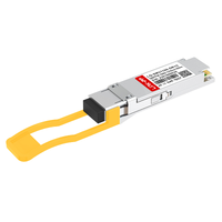
Are you struggling to scale your data center bandwidth to meet the demands of next-generation workloads without completely overhauling your physical fiber infrastructure? As high-density networks transition toward faster, more efficient architectures, the Mellanox MMS1V70-CM transceiver offers a streamlined pathway by delivering 100G throughput over a single optical wavelength. By leveraging this single-lambda standard, how can network operators bridge the gap between legacy hardware and the upcoming wave of high-speed deployments?
Have you ever wondered how your current 100G ports can seamlessly communicate with high-density 400G-DR4 switches? Traditional multi-lane optics often create a bottleneck during system upgrades, requiring complex and expensive cabling reconfigurations. By utilizing advanced optical signaling to enable clean, direct breakout configurations, this innovative module shows how easily legacy leaf-spine topologies can evolve into the 400G era.
➡️ What Is the MMS1V70-CM and Why It Matters for 400G-DR4 Evolution
The explosive growth of cloud computing and AI workloads requires a rapid shift toward ultra-high-density network architectures. The Mellanox MMS1V70-CM serves as a vital hardware catalyst in this transition, allowing legacy 100G infrastructure to interface directly with next-generation high-speed platforms. By consolidating optical signaling onto a single wavelength, this transceiver simplifies data center pathways and establishes a critical building block for scaling up to 400G networks.
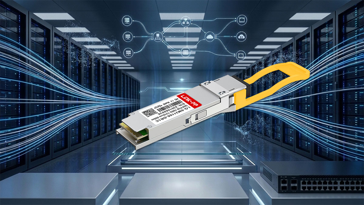
Demystifying the 100GBASE-DR1 Single-Lambda Optical Standard
Traditional 100G optical standards, such as 100G-SR4 or 100G-CWDM4, rely on multi-lane designs that transmit data over four separate optical fibers or wavelengths at 25Gbps per lane. In contrast, the 100GBASE-DR1 standard simplifies this process by consolidating the entire 100Gbps payload onto a single optical carrier (Single-Lambda) using advanced PAM4 (4-Level Pulse Amplitude Modulation) signaling.
By reducing the optical infrastructure to just one transmitter and one receiver, 100GBASE-DR1 drastically lowers hardware complexity and production costs. This streamlined physical layer design also yields significant power savings and reduces failure points, making it the preferred standard for modern, efficient optical transmission over single-mode fiber up to 500m.
Key Hardware Specifications of the Mellanox MMS1V70-CM Transceiver
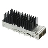
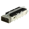
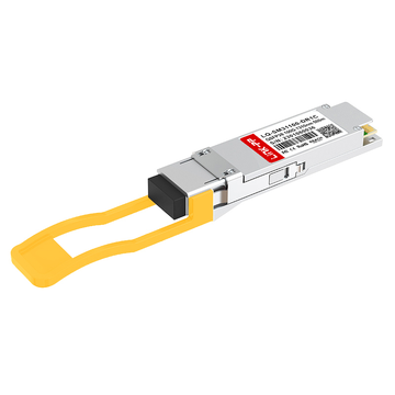
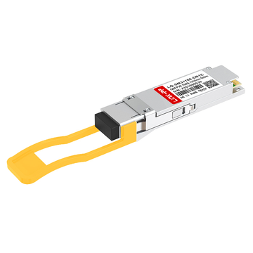
The Mellanox MMS1V70-CM is engineered inside a standard QSFP28 form factor, integrating an onboard Digital Signal Processor (DSP) to convert four lanes of 25Gbps NRZ electrical signals from the host switch into a single 100Gbps PAM4 optical channel. This compact transceiver architecture is optimized for low thermal dissipation, ensuring steady performance in high-density port environments.
The critical hardware parameters and operational baselines of this module are detailed in the table below.
| Parameter |
Specification Details |
| Form Factor |
QSFP28 |
| Optical Standard |
100GBASE-DR1 |
| Connector Type |
Duplex LC |
| Wavelength |
1310nm |
| Reach |
Up to 500m over SMF |
| Modulation |
53.125Gbaud PAM4 (Optical) / 4x 25Gbps NRZ (Electrical) |
| Power Consumption |
Max 4.0W |
How Single-Lambda 100G Technology Lays the Physical Foundation for 400G
Single-Lambda 100G technology represents a massive paradigm shift because it matches the exact per-lane optical speed of 400G architectures. A standard 400G-DR4 transceiver operates by grouping four independent 100G single-lambda streams together over a parallel fiber cable.
Because the MMS1V70-CM utilizes the exact same 100G PAM4 signaling scheme and 1310nm wavelength, it can communicate directly with one of those four channels. This alignment allows data centers to scale incrementally, matching optical lane rates across different generations of network hardware without needing active media converters.
Target Use Cases in Modern High-Density Spine-Leaf Architectures
In modern leaf-spine topologies, the MMS1V70-CM plays a versatile role by facilitating high-density interconnects between compute servers, storage arrays, and distribution switches. It serves as a cost-effective, low-power endpoint that prevents high-speed switches from being bottlenecked by legacy optical standards.
Specifically, network operators deploy this 100G-DR1 transceiver across several key functional areas within the physical layout:
- High-density leaf-to-server downlink connections to handle massive data bursts.
- Direct optical breakout applications linking 400G spine switches to 100G leaf switches.
- Inter-rack patching links over structured single-mode fiber panels up to 500m.
- Legacy switch integration to connect older 100G QSFP28 ports to next-generation fabric.
➡️ Understanding the Optical Specifications of MMS1V70-CM
Deploying high-speed single-lambda transceivers requires a clear understanding of their underlying physical and optical parameters. The Mellanox MMS1V70-CM is engineered with strict optical boundaries to maintain signal integrity over single-mode fiber infrastructure. Evaluating these specifications ensures optimal link performance, minimal bit error rates, and stable hardware operations in demanding data center environments.
Center Wavelength and Single-Mode Fiber Compatibility
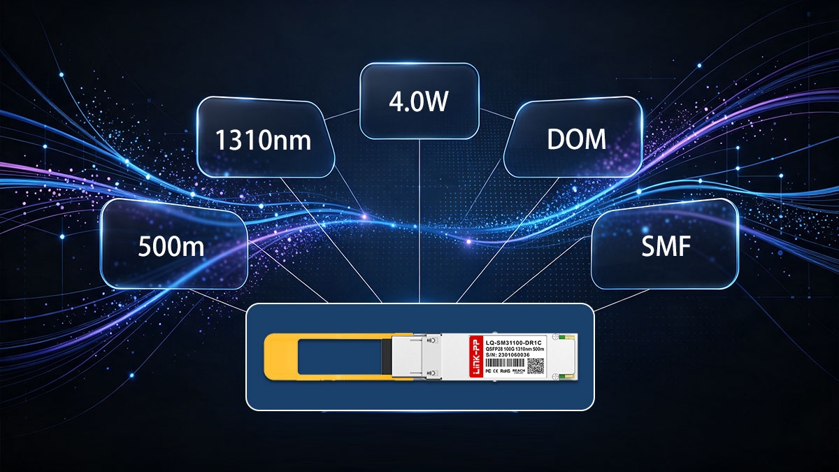
The MMS1V70-CM operates at a nominal center wavelength of 1310nm, which is the industry standard for short-reach single-mode fiber transmissions. This specific wavelength sits near the zero-dispersion point of standard OS2 single-mode fiber, effectively minimizing chromatic dispersion. By keeping pulse spreading to a minimum, the optical transceiver can cleanly transmit high-baud-rate PAM4 signals without losing wave shape over its designated reach.
Using standard OS2 single-mode fiber ensures full physical and optical compatibility across structured cabling systems. The 1310nm single-lambda design allows the module to integrate directly into existing single-mode fiber runs. This compatibility eliminates the need for expensive multi-mode to single-mode media conversion, facilitating a direct, low-loss physical layer connection.
Transmitter and Receiver Optical Power Budgets
To establish a reliable fiber link, the MMS1V70-CM maintains a precisely defined transmitter and receiver optical power budget. The optical transmitter launches a high-quality PAM4 signal within a specific average power range, ensuring the laser is strong enough to traverse the fiber path without overdriving the receiving optics. This strict power regulation is vital to prevent receiver overload, which can degrade signal processing and increase bit errors.
On the receiving end, the module features a highly sensitive optical receiver designed to detect weak, attenuated signals over distances up to 500m. The difference between the minimum transmitter launch power and the receiver sensitivity defines the allowable link budget, typically accommodating up to 3dB of loss. This budget must safely cover fiber attenuation and the cumulative insertion losses introduced by high-density patch panels and adapters.
Power Consumption Limits and Thermal Dissipation Standards
Operating within strict power limits, the Mellanox MMS1V70-CM is rated for a maximum power consumption of 4.0W. Keeping per-port power draw low is critical in high-density switches where dozens of QSFP28 slots run simultaneously. Minimizing power consumption directly translates to lower operational costs and eases the load on the facility’s power distribution units.
Thermal dissipation is managed through an optimized module casing designed to transfer heat away from the internal laser and DSP chipsets. The module operates reliably within a standard commercial temperature range of 0 to 70°C. Maintaining these thermal standards prevents thermal runaway and wavelength drift, protecting the transceiver from premature aging and unexpected link degradation.
Support for Digital Optical Monitoring in Real-Time Diagnostics
The MMS1V70-CM features built-in support for Digital Optical Monitoring (DOM), providing real-time access to critical operating parameters. Through a standard I²C interface compatible with the SFF-8636 management standard, network operators can query the transceiver’s internal diagnostics. This telemetry data is invaluable for proactively monitoring the health of the physical layer.
DOM continuously tracks vital operational metrics, including transceiver temperature, supply voltage, laser bias current, transmitted optical power, and received optical power. By establishing baselines and setting warning thresholds for these values, administrators can quickly isolate physical fiber faults, dirty connectors, or degrading lasers before a complete link-down event occurs.
➡️ How MMS1V70-CM Enables the Transition to 400G-DR4 Optics
Migrating high-density data center networks from legacy 100G configurations to modern 400G spine-leaf fabrics requires a highly strategic hardware approach. The Mellanox MMS1V70-CM serves as a vital bridge, enabling gradual and cost-effective upgrades without requiring a rip-and-replace overhaul of existing single-mode fiber systems. By aligning per-lane optical rates, this single-lambda transceiver ensures that enterprise fabrics can transition smoothly and incrementally toward a 400G-DR4 physical layer.
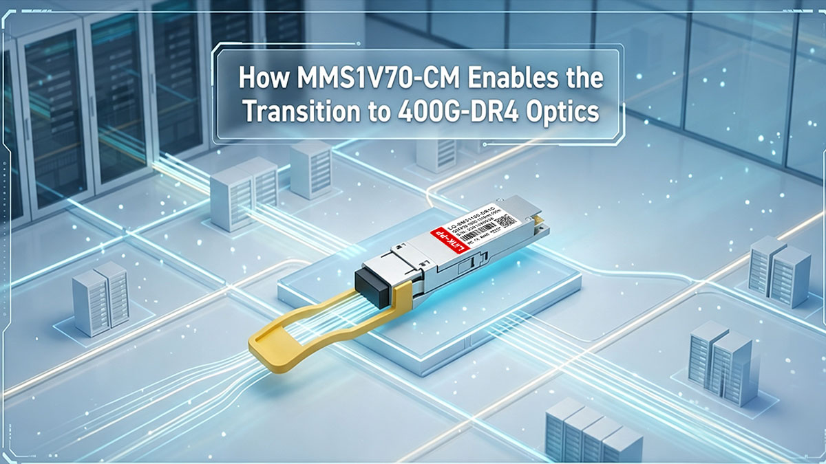
The Architectural Link Between 100G-DR1 and 400G-DR4
The fundamental design of 400G-DR4 optics is built upon a parallel transmission scheme that utilizes four independent 100G lanes, each operating on a single wavelength at 1310nm. Because the MMS1V70-CM uses the exact same 100GBASE-DR1 optical standard and PAM4 signaling, it shares an identical physical layer foundation with each lane of a 400G-DR4 transceiver. This optical symmetry enables a direct, native communication path between the two generations of hardware without needing active media converters.
This architectural alignment simplifies multi-generation networking by ensuring that optical lane rates are matched at 100Gbps per lambda. Instead of forcing an immediate, facility-wide upgrade of all endpoints, network architects can deploy 400G platforms in the core while keeping cost-sensitive edge servers and leaf switches running on reliable 100G QSFP28 modules. The seamless interoperability between these standards protects past hardware investments while clearing a clear path for future expansion.
Splitting 400G Ports into 4x 100G Channels Using MPO-to-LC Breakout Cabling
In high-density environments, a single 400G-DR4 port on a spine switch can be physically partitioned into four distinct 100G channels. This channelization is achieved using a passive MPO-12 to 4x Duplex LC single-mode breakout cable, which routes each of the four 100G PAM4 optical lanes to an individual LC connector. The Mellanox MMS1V70-CM connects directly to these split LC channels, establishing a clean point-to-point connection with the central 400G fabric.
This breakout topology provides massive density and cost benefits by maximizing the bandwidth utilization of high-radix 400G switches. Rather than dedicating entire 400G ports to single lower-speed connections, operators can aggregate traffic from four separate MMS1V70-CM leaf endpoints into a single QSFP-DD slot. This physical layer optimization dramatically reduces the number of active switch ports required at the spine, lowering the total cost of ownership.
Upgrading Your Spine-Leaf Topology without Replacing Existing Fiber Infrastructure
Deploying new structured cabling across a data center can be prohibitively expensive and logistically disruptive. The single-lambda design of the MMS1V70-CM mitigates this challenge by running high-speed 100G traffic over standard, pre-existing single-mode fiber runs. Because it matches the 1310nm wavelength profile used in next-generation 400G-DR4 optics, the transition to higher speeds requires no changes to the physical fiber distribution panels.
By maintaining single-mode compatibility, network operators can upgrade leaf switches to 100G single-lambda and spine platforms to 400G-DR4 while keeping the same optical distribution frames in place. This approach allows the physical infrastructure to remain untouched during the transition. Enterprises can scale their backplane capacity in a phased manner, matching capital expenditure to actual bandwidth demand.
Migrating from Legacy 4x 25G NRZ (QSFP28) to Next-Gen QSFP-DD
Legacy 100G transceivers, such as 100G-SR4 or 100G-LR4, rely on multi-lane signaling (4x 25G NRZ) that is physically incompatible with the single-lambda lanes of 400G switches. The MMS1V70-CM solves this incompatibility by packaging an advanced DSP inside a standard QSFP28 housing, allowing legacy switches to output 100G via a single PAM4 wavelength. This capability enables older hardware to communicate directly with next-generation QSFP-DD 400G-DR4 platforms.
By bridging the signaling gap, the module eliminates the need to retire perfectly functional legacy switches prematurely. It provides a highly reliable, low-power integration pathway that keeps multi-generation systems working in harmony. This smooth migration path helps data center managers transition their physical layer smoothly, ensuring that older legacy systems remain productive throughout the migration to 400G.
➡️ Optical Modulation Mechanics: PAM4 Signaling in MMS1V70-CM
Achieving 100Gbps transmission over a single optical wavelength requires a fundamental shift in how binary data is encoded. The Mellanox MMS1V70-CM transitions from legacy binary signaling to high-level multi-amplitude modulation to maximize spectral efficiency. This advanced modulation scheme enables the module to maintain excellent signal integrity while keeping physical channel requirements simple.
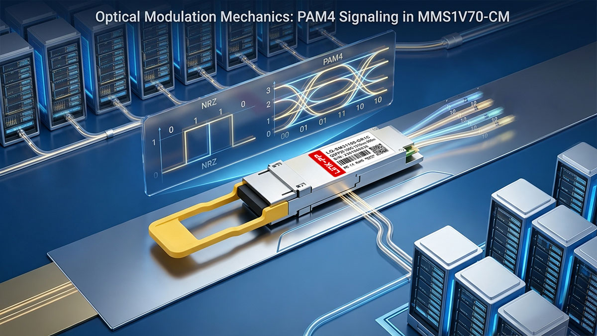
Transitioning from NRZ to PAM4: Why Baud Rate Matters
Traditional high-speed transceivers utilize Non-Return-to-Zero (NRZ) modulation, which represents data using two optical amplitude levels to transmit 1 bit per symbol. To achieve 100Gbps with NRZ, the physical components would need to operate at an extremely high electrical baud rate, creating severe signal degradation and thermal challenges. The MMS1V70-CM solves this bottleneck by employing 4-Level Pulse Amplitude Modulation (PAM4).
By utilizing four distinct voltage levels, PAM4 encodes 2 bits of data into each optical symbol, effectively doubling the transmission capacity at any given symbol rate. This allows the optical transceiver to deliver a full 100Gbps throughput while operating at a manageable baud rate of 53.125Gbaud. Reducing the physical modulation speed preserves signal quality, keeps power consumption low, and allows the use of more cost-effective optical components.
Signal Integrity and Eye Diagram Performance at 53Gbaud
Operating at a high speed of 53.125Gbaud requires strict signal integrity standards to ensure error-free data decoding at the receiving endpoint. Because PAM4 relies on four distinct signal levels, its corresponding eye diagram features three vertically stacked "eyes" rather than the single eye pattern found in legacy NRZ links. This smaller vertical opening means the optical receiver must be highly sensitive to distinguish between the four amplitude levels.
Maintaining a clean and wide eye diagram is critical for the MMS1V70-CM to prevent signal degradation over single-mode fiber runs. Any physical channel noise, jitter, or non-linearities can quickly close these narrow optical eyes, resulting in immediate packet loss. The module is engineered with high-linearity lasers and optimized optical drivers to preserve vertical eye margin and ensure stable, low-noise performance.
Handling Multipath Interference (MPI) in Single-Lambda Channels
Single-lambda networks operating over 1310nm SMF are particularly susceptible to Multipath Interference (MPI), which occurs when optical signals reflect off internal connector joints and recombine out of phase. In high-speed PAM4 links, even minor reflections can distort the optical amplitude, causing severe decoding errors at the receiver.
To mitigate these signal distortions and secure reliable link stability, network engineers rely on targeted physical and configuration rules:
- Using Angled Physical Contact (APC) connectors to direct back-reflections into the fiber cladding.
- Minimizing the number of mating interfaces across high-density single-mode fiber patching paths.
- Deploying low-reflection physical couplers that maintain a high return loss metric.
- Applying real-time adaptive DSP equalization inside the module to mathematically cancel out residual multipath reflections.
The Role of Digital Signal Processing (DSP) in Maintaining Link Stability
The onboard Digital Signal Processing (DSP) silicon inside the MMS1V70-CM acts as the primary brain of the optical transceiver, managing the complex translation between electrical and optical layers. This powerful processor continually analyzes incoming signals, correcting physical distortions caused by chromatic dispersion and noise.
To preserve an error-free transmission path, the DSP executes several critical signal-reconstruction processes:
- Performing high-speed Analog-to-Digital Conversion (ADC) to digitize the incoming optical wave shape.
- Applying Feed-Forward Equalization (FFE) to mitigate inter-symbol interference across the fiber link.
- Utilizing Decision Feedback Equalization (DFE) to dynamically clean up high-frequency noise.
- Re-timing electrical lanes to eliminate high-frequency phase jitter before transmitting data to the host ASIC.
➡️ Physical Layer Breakout & Cabling Integration for MMS1V70-CM
Integrating 100G single-lambda optics into modern parallel infrastructure requires a well-structured physical layer design. Successfully deploying the Mellanox MMS1V70-CM depends on aligning physical connectors, optical fibers, and patch pathways with the overarching 400G-DR4 cable design. This physical harmony guarantees reliable high-density connectivity while simplifying ongoing network scaling.
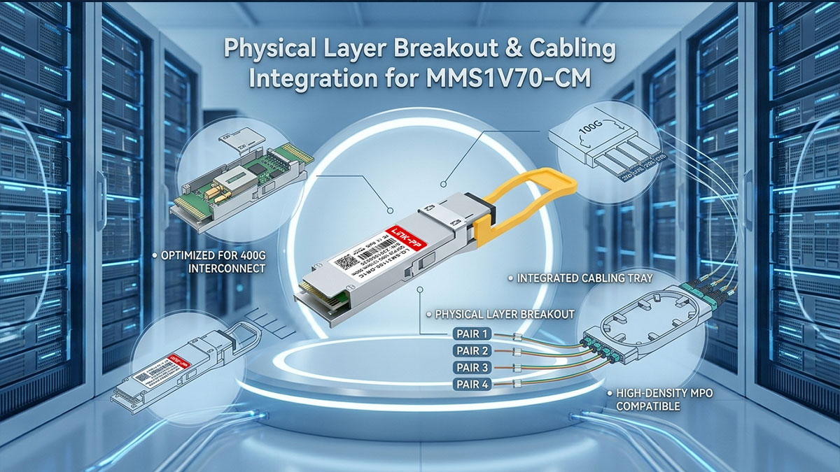
Connecting Duplex LC Transceivers to Parallel MPO Structured Cabling
The Mellanox MMS1V70-CM features a standard Duplex LC physical interface, which is designed for point-to-point single-mode fiber links. To integrate these modules into a high-density 400G-DR4 backbone, structured cabling systems use passive conversion modules or breakout cassettes. These passive systems transition the multi-fiber MPO-12 trunk lines coming from high-speed switches into individual, duplex LC distribution ports.
This deployment strategy enables neat cable management within network racks and avoids cluttered point-to-point connections. By patching the duplex LC ends of the MMS1V70-CM directly into a structured breakout cassette, physical-layer technicians can seamlessly route single channels of a 400G-DR4 port back to legacy 100G network switches.
Maximizing the 500-Meter Reach: 100GBASE-DR1 Limits over Single-Mode Fiber
The 100GBASE-DR1 optical specification defines a maximum operational reach of 500m when deployed over OS2 single-mode fiber. This distance limit is optimized for high-density intra-data center links, spanning the distance between server cabinets and core distribution frames. Running the MMS1V70-CM within this 500-meter physical boundary keeps fiber dispersion low, maintaining high signal quality without requiring active optical amplification.
Exceeding this 500-meter link limit increases the risk of optical signal degradation and timing issues on the high-speed PAM4 path. Ensuring that your fiber runs stay safely inside this distance envelope guarantees that the transceiver's laser signal arrives at the destination with enough clarity to be reconstructed by the receiving DSP.
Calculating Insertion Loss Budgets for Multi-Channel MPO-to-LC Breakouts
Implementing multi-channel MPO-to-LC breakout links introduces several mating interfaces, each contributing to cumulative insertion loss. Since the 100GBASE-DR1 standard has a tightly restricted optical power budget, calculating the exact decibel (dB) loss across every connector is essential. Every passive adapter, splice, and patch panel interface along the channel must be budgeted to prevent the optical signal from dropping below acceptable receiving levels.
A standard 400G-DR4 to MMS1V70-CM breakout path should ideally keep total insertion loss below 3.0dB to ensure steady performance. Using low-loss MPO connectors and ultra-precise LC patch panels helps maintain a strong optical power margin, protecting the network from intermittent packet drops or total link failure.
Implementing Structural Fiber End-Face Inspection Standards to Prevent Receiver Damage
High-density PAM4 signaling relies on highly focused optical lasers, making the integrity of the physical fiber end-faces a critical structural design standard. Even tiny dust particles on a connector end-face can cause localized power reflection and signal distortion under high power densities. Implementing structural end-face inspection during initial cabling deployment ensures optical pathways are completely clear of physical contaminants before light passes through.
Following structural inspection and testing standards, such as IEC 61300-3-35, is vital to avoid receiver overload and saturation issues on sensitive optical detectors. Rather than relying on reactive troubleshooting, establishing rigorous testing standards ensures stable signal transmission and meets essential eye-safety regulations across high-density fiber networks.
➡️ Aligning FEC Settings on the MMS1V70-CM for a Seamless 400G Upgrade
Configuring Forward Error Correction (FEC) is one of the most critical software steps when integrating single-lambda optics into a high-speed network fabric. The Mellanox MMS1V70-CM relies on host-side error correction to maintain robust data transmission across physical fiber runs. Aligning these logical settings between your 100G endpoints and 400G-DR4 ports is essential to prevent system mismatches and guarantee a seamless hardware upgrade.
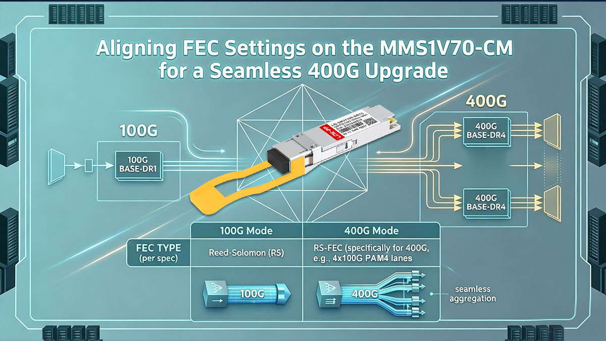
Understanding Host-Side KP4 FEC: Why Single-Lambda 100G Requires It
Because PAM4 signaling utilizes four amplitude levels instead of two, its smaller eye openings make the physical signal much more susceptible to background noise and minor reflections. To offset this physical vulnerability, the IEEE 802.3 standard mandates the use of host-side Reed-Solomon Forward Error Correction (specifically RS-FEC(544,514), commonly known as KP4 FEC). The MMS1V70-CM requires the host switch ASIC to append mathematical parity bits to the outgoing electrical data streams to recover corrupt packets at the receiving end.
Without KP4 FEC active on the switch port, a single-lambda 100G link cannot achieve stable physical layer operation. This error-correction mechanism operates under strict architectural guidelines to ensure optical transport stability:
- Requiring host ASIC processing to append and decode Reed-Solomon parity blocks.
- Operating strictly at the physical layer to correct random bit errors before they reach the MAC layer.
- Providing unified error tolerance that matches the per-lane FEC coding of 400G-DR4 ports.
- Eliminating the need for optical retransmissions by reconstructing damaged data packets in real time.
The 10⁻¹² BER Threshold: Keeping Packet Loss at Zero Across 100G and 400G Links
The ultimate goal of deploying KP4 FEC on the MMS1V70-CM is to achieve a highly reliable Post-FEC Bit Error Rate (BER) of 10⁻¹² or lower. While the raw, uncorrected signal (Pre-FEC BER) over the single-mode fiber may occasionally degrade to around 10⁻⁴ due to attenuation or noise, the FEC algorithm easily identifies and repairs these corrupted bits. This continuous mathematical cleanup drops the final packet loss metric to zero.
Maintaining this strict 10⁻¹² threshold is what makes breakout connections between 100G and 400G links completely reliable. Because both the 400G-DR4 switch ports and the MMS1V70-CM target this exact same error threshold, data flows seamlessly between different generations of hardware without performance degradation. This consistent error margin is vital for sustaining high-throughput, enterprise-grade cloud traffic.
Minimizing FEC Latency: Balancing Error Correction with Real-Time Performance
While Forward Error Correction is necessary for signal stability, the process of calculating and appending mathematical parity blocks inevitably introduces minor processing latency. In ultra-low-latency environments, such as InfiniBand fabrics, high-frequency trading networks, and high-performance computing (HPC) clusters, even a few nanoseconds of delay can impact application efficiency. Network architects must carefully evaluate this processing overhead when configuring the MMS1V70-CM.
To maintain an optimal balance, the onboard DSP and host switch work in tandem to process the KP4 FEC algorithm with maximum hardware efficiency. Although disabling FEC is not an option for single-lambda 100G optics due to signal integrity demands, utilizing high-performance switch ASICs ensures that the latency penalty remains minimal. This configuration keeps real-time packet processing fast while preserving complete error-correction protection across the link.
Troubleshooting Link-Down Events: Resolving FEC Mismatches on Legacy Hardware
When installing the MMS1V70-CM in legacy 100G switches, the most common installation obstacle is a complete failure to establish a physical link (Link-Down). Many older 100G QSFP28 platforms default to KR4 FEC (RS-FEC(528,514)) or turn off FEC entirely, which is completely incompatible with next-generation single-lambda standards. Resolving these software mismatches requires a systematic troubleshooting approach to force alignment across the network.
If your transceiver experiences a persistent Link-Down status during a 400G upgrade, follow these configuration procedures to restore port connectivity:
- Manually set the switch port FEC mode to KP4 FEC via the Command Line Interface (CLI).
- Deactivate auto-negotiation on the port to prevent the switch from defaulting to incompatible legacy FEC modes.
- Verify that the connected 400G-DR4 breakout port is actively configured for 100G channelized operation.
- Update the switch operating system firmware to ensure full command support for single-lambda optical transceivers.
➡️ Final Thoughts on the Role of MMS1V70-CM in the 400G-DR4 Era
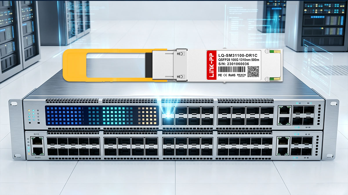
The Mellanox MMS1V70-CM is a critical architectural stepping stone into the high-density 400G-DR4 era. By matching the single-lambda PAM4 lanes of next-generation switches, this transceiver allows operators to scale their networks incrementally without high upgrade costs. It successfully bridges the gap between different hardware generations, ensuring legacy 100G systems remain highly productive.
If you are planning your own network migration, choosing reliable, fully compatible optical transceivers is key to preventing link-down issues and maintaining signal integrity. You can find a high-performance MMS1V70-CM 100GBASE-DR compatible module at the LINK-PP Official Store. Explore our optical transceivers today to find the perfect match for your data center upgrade.