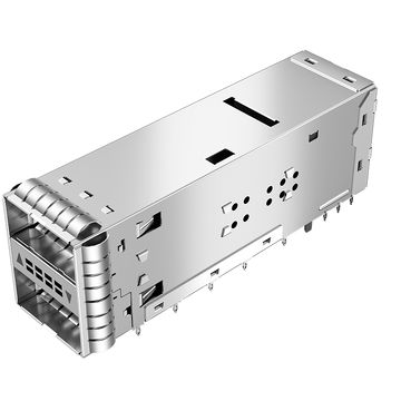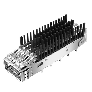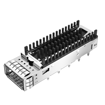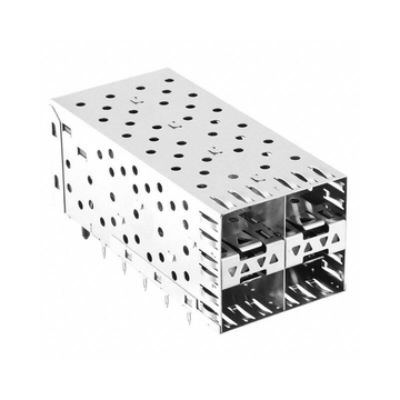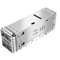
Con l'evoluzione delle piattaforme di rete verso la connettività ottica a 800G, la compatibilità elettromagnetica (EMC) e le interferenze elettromagnetiche (EMI) assumono un'importanza sempre maggiore a livello di sistema. Interfacce elettriche più veloci, porte ottiche più dense, transizioni di segnale più rapide e layout dello chassis più compatti possono rendere più difficile il controllo dell'energia elettromagnetica indesiderata. Di conseguenza, ogni componente che circonda l'interfaccia ad alta velocità può contribuire al comportamento EMC complessivo, inclusi i componenti che non elaborano o trasmettono attivamente segnali.
Un alloggiamento per fibra ottica è spesso considerato principalmente una struttura meccanica che sostiene e allinea un ricetrasmettitore ottico. Tuttavia, in una piattaforma 800G, le sue superfici conduttive, i contatti di messa a terra, le aperture e l'interfaccia con lo chassis possono influenzare l'efficacia della schermatura e i percorsi di corrente ad alta frequenza. Ciò solleva un'importante questione: perché un alloggiamento per fibra ottica apparentemente passivo può diventare un "custode nascosto" per la conformità alle normative FCC e CE?
Questo articolo esamina la relazione tra la progettazione del Cage Assembly 800G e le prestazioni EMC a livello di sistema, concentrandosi su:
- Come una gabbia passiva influenza la generazione, l'accoppiamento e i percorsi di dispersione delle interferenze elettromagnetiche.
- Perché la messa a terra, l'integrità dei contatti, le aperture e i materiali sono importanti a 800G
- Come la progettazione del gruppo gabbia interagisce con l'integrità del segnale e i requisiti termici
- Dove la gabbia si inserisce nella conformità FCC/CE e nella certificazione di sistema
- Come convalidare i progetti delle gabbie prima dei test EMC formali
La comprensione di questi fattori aiuta gli ingegneri a considerare l'assemblaggio della gabbia come parte integrante dell'architettura EMC complessiva, piuttosto che come un componente meccanico isolato, riducendo il rischio che dettagli strutturali apparentemente secondari si trasformino in importanti problemi di certificazione.
🧾 Cosa rende un gruppo gabbia da 800G un componente critico per la compatibilità elettromagnetica?
Un alloggiamento per cavi a 800G è critico dal punto di vista della compatibilità elettromagnetica (EMC) perché si trova direttamente attorno all'interfaccia del modulo elettrico e ottico ad alta velocità, collegandosi al contempo allo chassis dell'apparecchiatura. Sebbene l'alloggiamento non generi o elabori direttamente segnali dati, la sua struttura conduttiva, i contatti di messa a terra, le aperture e le interfacce meccaniche possono influenzare la schermatura elettromagnetica, i percorsi di ritorno della corrente e le emissioni irradiate. A 800G, questi effetti diventano sempre più significativi perché la maggiore velocità di segnalazione e la maggiore densità di porte lasciano meno margine per le imperfezioni EMC.
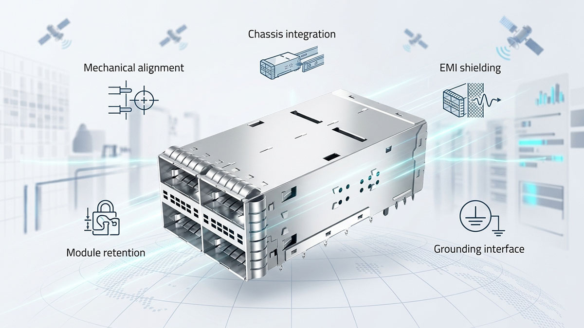
Il ruolo elettrico e meccanico di una gabbia in fibra
Una gabbia per fibre ottiche svolge una funzione che va oltre il semplice contenimento meccanico: definisce l'ambiente fisico e conduttivo che circonda un ricetrasmettitore ottico. In una piattaforma 800G ad alta densità, questo rende il gruppo gabbia un componente di interfaccia tra il ricetrasmettitore, il PCB, il pannello frontale e lo chassis.
Le sue funzioni principali in genere includono:
- Conservazione dei moduli: Mantiene il ricetrasmettitore ottico saldamente posizionato all'interno dell'apparecchiatura host.
- Allineamento meccanico: Mantiene la posizione corretta tra il modulo, il connettore, il circuito stampato e l'apertura del pannello frontale.
- Integrazione del telaio: Fornisce un'interfaccia meccanica definita tra l'area del ricetrasmettitore e l'involucro dell'apparecchiatura.
- Schermatura EMI: Contribuisce a contenere l'energia elettromagnetica ad alta frequenza intorno al modulo e alla zona del connettore.
- Interfaccia di messa a terra: Garantisce un contatto conduttivo tra la struttura della gabbia e il telaio o l'architettura di schermatura circostante.
Queste funzioni sono interconnesse, non indipendenti. Ad esempio, una gabbia che mantiene l'allineamento meccanico ma presenta uno scarso contatto conduttivo con il telaio potrebbe comunque consentire la fuoriuscita di energia RF indesiderata. Pertanto, l'assemblaggio della gabbia deve essere valutato come parte integrante dell'interfaccia meccanico-elettrica completa.
Perché passivo non significa neutro rispetto alla compatibilità elettromagnetica.
Un assemblaggio di gabbie passive non è neutrale dal punto di vista della compatibilità elettromagnetica (EMC) perché la sua struttura conduttiva può modificare i percorsi di corrente ad alta frequenza, la distribuzione del campo elettromagnetico e i percorsi di dispersione attorno all'interfaccia del ricetrasmettitore. La sua influenza deriva dal modo in cui interagisce con le strutture conduttive e non conduttive circostanti, non da alcuna funzione elettronica attiva.
Diverse caratteristiche della gabbia possono influenzare questo comportamento:
- Superfici conduttive: Fornire una barriera fisica in grado di contenere i campi elettromagnetici.
- Contatti di messa a terra: Creare percorsi conduttivi tra la gabbia e il telaio.
- Spazi meccanici: Possono diventare potenziali punti di dispersione di radiofrequenza quando la continuità della schermatura viene interrotta.
- Impedenza di contatto: Determina l'efficacia con cui le correnti ad alta frequenza possono attraversare le interfacce.
- Geometria della gabbia: Influisce sulla distribuzione del campo e sull'accoppiamento tra porte ad alta velocità adiacenti.
Ecco perché classificare semplicemente un componente come "passivo" può essere fuorviante durante un'analisi EMC. Una piccola modifica nella geometria della gabbia, nella placcatura, nella disposizione delle molle o nel contatto con il telaio può alterare l'ambiente elettromagnetico anche quando il ricetrasmettitore ottico e il PCB sottostanti rimangono invariati.
Perché 800G aumenta la pressione di progettazione EMC
Le piattaforme 800G impongono una maggiore pressione elettromagnetica (EMC) al Cage Assembly, poiché le interfacce elettriche ad alta velocità, la fitta disposizione delle porte e le rapide transizioni di segnale creano un ambiente elettromagnetico più esigente. La velocità di trasmissione aggregata nominale di 800 Gbps non è, di per sé, l'unico fattore determinante; anche il contenuto ad alta frequenza associato alle rapide transizioni elettriche e l'implementazione fisica dell'interfaccia sono importanti.
Le principali sfide includono:
- Segnalazione elettrica ad alta velocità: Le transizioni più rapide contengono più energia ad alta frequenza che può accoppiarsi con le strutture vicine.
- Maggiore densità di porte: La vicinanza tra gabbie e moduli aumenta la possibilità di accoppiamento elettromagnetico.
- Riduzione della distanza fisica: Le configurazioni dense del pannello frontale offrono meno spazio per le strutture di isolamento e schermatura.
- Conversione in modo comune: Percorsi di ritorno imperfetti possono convertire l'attività in modalità differenziale in correnti in modalità comune che hanno maggiori probabilità di irradiarsi.
- Vincoli termici: Aperture più ampie o strutture della gabbia modificate possono migliorare il flusso d'aria, ma possono anche influire sul contenimento elettromagnetico.
Di conseguenza, un assemblaggio di gabbie 800G deve essere considerato all'interno della più ampia architettura EMC. Le sue dimensioni meccaniche, le interfacce conduttive, la strategia di messa a terra e le strutture circostanti del PCB e dello chassis possono determinare collettivamente se l'interfaccia ad alta velocità rimane adeguatamente contenuta durante il funzionamento del sistema.
🧾 In che modo una gabbia passiva influenza le interferenze elettromagnetiche a 800 g?
Un assemblaggio di gabbie passive influenza le interferenze elettromagnetiche (EMI) a 800G principalmente controllando il modo in cui l'energia elettromagnetica ad alta frequenza viene contenuta, accoppiata e riflessa all'interno dell'apparecchiatura. Non genera né sopprime attivamente le interferenze, ma la sua struttura conduttiva e le sue interfacce possono mantenere o alterare il confine RF previsto. A 800G, la segnalazione elettrica ad alta velocità, il posizionamento denso dei moduli e le rapide transizioni di segnale rendono questi effetti più rilevanti per le prestazioni EMC complessive.
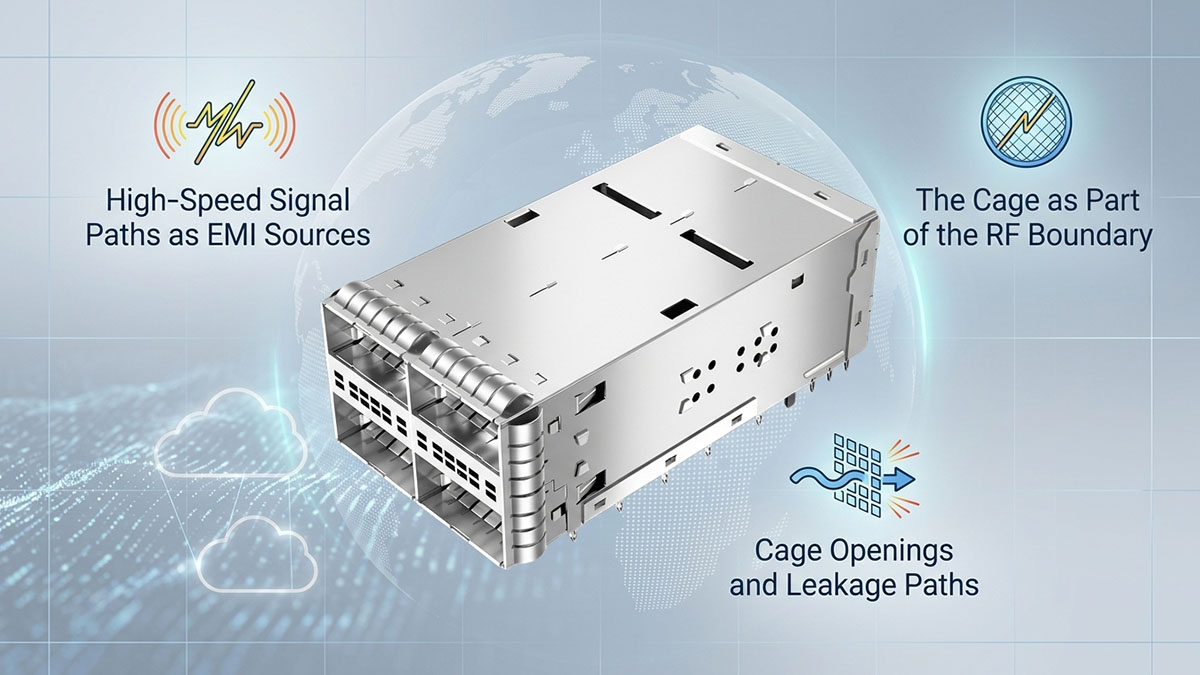
Percorsi di segnale ad alta velocità come sorgenti di interferenze elettromagnetiche.
I percorsi di segnale ad alta velocità attorno a un ricetrasmettitore ottico 800G possono diventare fonti significative di energia elettromagnetica, poiché le rapide transizioni elettriche contengono componenti ad alta frequenza sostanziali. Anche quando l'interfaccia utilizza la segnalazione differenziale, la simmetria imperfetta e le discontinuità possono produrre correnti di modo comune che si accoppiano alla gabbia, allo chassis, al PCB o alle strutture vicine.
Diversi meccanismi risultano particolarmente rilevanti:
- Transizioni di segnale rapide: Le rapide variazioni di tensione e corrente contengono componenti spettrali ad alta frequenza che possono accoppiarsi alle strutture circostanti.
- Discontinuità del percorso di ritorno: Un percorso di ritorno interrotto o mal controllato può aumentare la corrente di modo comune.
- Transizioni dei connettori: L'area tra il circuito stampato, il connettore elettrico e il modulo ottico può introdurre discontinuità di impedenza e del piano di riferimento.
- Accoppiamento porta-porta: Le interfacce 800G posizionate vicine possono trasferire energia elettromagnetica tra canali adiacenti.
- Accoppiamento del telaio: Correnti ad alta frequenza incontrollate possono raggiungere strutture metalliche di grandi dimensioni e contribuire alle emissioni irradiate.
L'assemblaggio della gabbia diventa importante perché circonda gran parte di questa regione di interfaccia. Una gabbia ben integrata può contribuire a stabilire un confine conduttivo controllato, mentre una messa a terra inadeguata o un contatto discontinuo possono fornire ulteriori percorsi per la fuoriuscita dell'energia elettromagnetica.
Aperture della gabbia e vie di fuga
Le aperture della gabbia e gli spazi meccanici possono influenzare le interferenze elettromagnetiche (EMI) perché interrompono un confine conduttivo altrimenti continuo. Alle alte frequenze, anche discontinuità relativamente piccole possono diventare percorsi di dispersione rilevanti, soprattutto quando più aperture si trovano in prossimità di interfacce elettriche ad alta velocità.
Il potenziale impatto delle interferenze elettromagnetiche dipende da diversi fattori strutturali:
- Dimensioni di apertura: Aperture più ampie possono offrire maggiori opportunità di dispersione elettromagnetica.
- Continuità delle interruzioni: Gli spazi continui tra la gabbia e il telaio possono indebolire la continuità della schermatura.
- Compatibilità tra modulo e gabbia: Uno scarso contatto meccanico può lasciare aperture indesiderate intorno al ricetrasmettitore inserito.
- Distanza tra le gabbie adiacenti: Aperture multiple e ravvicinate possono aumentare l'accoppiamento tra le porte adiacenti.
- Integrazione nel pannello frontale: La relazione tra la gabbia, la lunetta e il telaio determina se il confine di schermatura rimane continuo.
Questi effetti non devono essere valutati esclusivamente in base alle dimensioni meccaniche nominali. Le tolleranze di assemblaggio, l'inserimento dei moduli, la deformazione dei contatti a molla e le variazioni di produzione possono modificare il confine elettromagnetico effettivo. Pertanto, l'apertura della gabbia deve essere considerata insieme all'intera interfaccia tra ricetrasmettitore e chassis.
La gabbia come parte del confine RF
L'assemblaggio della gabbia deve essere considerato parte del perimetro RF dell'apparecchiatura poiché collega fisicamente la regione del modulo ad alta velocità con l'ambiente conduttivo del telaio. La sua efficacia dipende dal mantenimento della continuità elettrica attraverso la gabbia, il telaio, il pannello frontale e l'interfaccia del modulo, piuttosto che dal solo materiale della gabbia.
Il confine RF può essere compreso attraverso diverse interfacce connesse:
- Interfaccia tra gabbia e telaio: Determina l'efficacia con cui le correnti ad alta frequenza possono fluire nella struttura di schermatura del telaio.
- Interfaccia tra gabbia e PCB: Influisce sulla transizione tra la struttura di riferimento a livello di scheda e la gabbia metallica.
- Interfaccia tra gabbia e modulo: Determina se il ricetrasmettitore ottico inserito mantiene la continuità della schermatura.
- Interfaccia tra la gabbia e il pannello frontale: Contribuisce a controllare le dispersioni elettromagnetiche intorno all'apertura esterna dell'apparecchiatura.
- Interfaccia tra gabbie adiacenti: Diventa sempre più importante con l'aumentare della densità delle porte 800G.
Ecco perché un gruppo di celle di protezione non può essere valutato isolatamente durante l'analisi delle interferenze elettromagnetiche (EMI) a 800G. Le sue prestazioni effettive derivano dalla completa interazione meccanica ed elettrica tra il modulo ottico, il connettore, il PCB, lo chassis, il pannello frontale e il sistema di messa a terra. Una cella passiva, pertanto, agisce meno come una schermatura a sé stante e più come una sezione critica del percorso complessivo di contenimento delle radiofrequenze del sistema.
🧾 Perché la messa a terra e la qualità dei contatti sono più importanti per 800G
La messa a terra e la qualità dei contatti assumono maggiore importanza a 800G, poiché un assemblaggio di gabbie deve fornire un percorso conduttivo continuo a bassa impedenza per le correnti ad alta frequenza, mantenendo al contempo un'efficace schermatura EMI attorno alle interfacce ad alta velocità densamente impacchettate. Una gabbia può essere realizzata con un materiale conduttivo eccellente e comunque avere prestazioni scadenti se i suoi contatti del telaio, le molle di fissaggio, i punti di montaggio o le interfacce dei moduli introducono un'impedenza eccessiva o delle discontinuità. A 800G, questi dettagli di interfaccia apparentemente insignificanti possono diventare fattori determinanti per il comportamento EMC a livello di sistema.
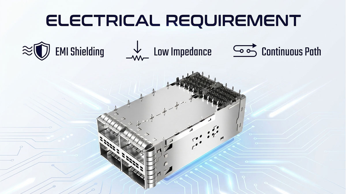
Massa del telaio vs. massa del segnale
In un sistema di rete ottica 800G, la massa del telaio e la massa del segnale svolgono funzioni correlate ma distinte. Il gruppo di schermatura (Cage Assembly) partecipa principalmente al dominio del telaio o della schermatura, mentre l'interfaccia elettrica ad alta velocità ha una propria struttura di ritorno del segnale controllata. Mantenere queste funzioni ben definite contribuisce a impedire che correnti ad alta frequenza indesiderate seguano percorsi imprevedibili all'interno dell'apparecchiatura.
Tale distinzione può essere analizzata attraverso diverse considerazioni:
- Massa del segnale: Fornisce il percorso di riferimento e di ritorno controllato associato alla segnalazione elettrica ad alta velocità.
- Telaio di base: Fornisce un riferimento conduttivo per la schermatura, le strutture di contenimento e le correnti elettromagnetiche indesiderate.
- Messa a terra della gabbia: Collega la struttura metallica a gabbia al telaio circostante o all'architettura di schermatura.
- Controllo del percorso di ritorno: Contribuisce a impedire che l'energia ad alta frequenza si propaghi attraverso strutture conduttive indesiderate.
- Continuità dell'interfaccia: Garantisce una transizione prevedibile tra la gabbia, il telaio e le superfici di schermatura circostanti.
L'obiettivo non è quello di rendere ogni struttura conduttiva parte dello stesso percorso di ritorno del segnale. Piuttosto, l'assemblaggio della gabbia dovrebbe integrarsi con l'architettura di messa a terra del telaio in modo controllato, in modo che le correnti di schermatura possano essere contenute senza compromettere l'integrità del segnale ad alta velocità.
Resistenza di contatto e comportamento ad alta frequenza
La sola resistenza di contatto non descrive completamente le prestazioni di messa a terra del gruppo gabbia a 800G, poiché il comportamento ad alta frequenza è influenzato anche dall'induttanza, dalla geometria dei contatti, dalla distribuzione della corrente e dalla continuità dell'interfaccia. Una connessione che appare elettricamente adeguata nelle misurazioni in corrente continua può comunque presentare un'impedenza significativa quando attraversata da corrente ad alta frequenza.
Le caratteristiche di contatto importanti includono:
- Area contatti: Interfacce conduttive più ampie e uniformi possono fornire un percorso di corrente più affidabile.
- Pressione di contatto: Una forza elastica adeguata contribuisce a mantenere un contatto elettrico stabile nonostante le variazioni meccaniche.
- Stato della superficie: L'ossidazione, la contaminazione o un trattamento superficiale inadeguato possono aumentare l'impedenza dell'interfaccia.
- Geometria di contatto: La forma fisica e la lunghezza del percorso conduttivo influenzano il suo comportamento induttivo ad alta frequenza.
- Stabilità meccanica: Vibrazioni, cicli termici e ripetuti inserimenti dei moduli possono influire sulla consistenza dei contatti a lungo termine.
Questa distinzione è particolarmente importante per i sistemi 800G perché le prestazioni EMC non possono essere previste unicamente in base a una bassa resistenza CC misurata. La questione rilevante è se l'assemblaggio della gabbia mantenga un percorso conduttivo efficace a bassa impedenza attraverso le frequenze associate all'ambiente elettromagnetico ad alta velocità del sistema.
Garantire la continuità di messa a terra attraverso la gabbia
Garantire la continuità di messa a terra dell'intero gruppo gabbia è essenziale, poiché la gabbia, il PCB, il pannello frontale, lo chassis e l'alloggiamento del modulo determinano collettivamente se il confine di schermatura previsto rimane elettricamente continuo. Qualsiasi discontinuità significativa può costringere le correnti ad alta frequenza a cercare percorsi alternativi, potenzialmente aumentando i campi elettromagnetici locali o le emissioni irradiate.
Un'interfaccia di messa a terra robusta dovrebbe quindi considerare:
- Contatto tra gabbia e telaio: Fornisce il collegamento conduttivo primario tra la gabbia e l'involucro.
- Collegamento tra gabbia e PCB: Integra la gabbia con la struttura meccanica e di messa a terra a livello della scheda.
- Continuità del pannello frontale: Aiuta a prevenire perdite intorno all'apertura del modulo esterno.
- Contatto per gli alloggi modulari: Garantisce la continuità della schermatura dopo l'installazione del ricetrasmettitore ottico.
- Punti di contatto multipli: Se opportunamente progettato, può ridurre l'impedenza effettiva del percorso di schermatura.
Anche le tolleranze meccaniche sono altrettanto importanti. Un dito della molla che perde una pressione sufficiente, una superficie di montaggio con variazioni eccessive o un'incoerenza della placcatura possono creare una discontinuità di messa a terra localizzata. Per questo motivo, la validazione dell'assemblaggio della gabbia 800G dovrebbe considerare non solo il progetto nominale, ma anche le tolleranze di assemblaggio e le condizioni che possono verificarsi durante la vita operativa dell'apparecchiatura.
🧾 Conformità FCC e CE: dove si colloca la gabbia?
Un gruppo gabbia rientra nella conformità FCC e CE come elemento di progettazione EMC a livello di sistema , non come scorciatoia indipendente per la certificazione. La conformità FCC e CE viene generalmente valutata rispetto ai requisiti applicabili all'apparecchiatura completa, mentre la gabbia può influenzare il comportamento delle emissioni di tale apparecchiatura attraverso la sua schermatura, la messa a terra, l'integrità dei contatti e le interfacce meccaniche. Pertanto, un gruppo gabbia 800G dovrebbe essere considerato parte dell'architettura EMC fin dalla fase di progettazione, piuttosto che come un componente puramente meccanico.
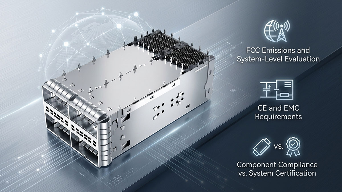
Valutazione delle emissioni e a livello di sistema da parte della FCC
La valutazione EMC della FCC si concentra sul comportamento delle apparecchiature elettroniche finite in base ai requisiti applicabili, comprese le emissioni elettromagnetiche indesiderate. L'assemblaggio della gabbia può influenzare questo risultato perché circonda una regione contenente interfacce elettriche ad alta velocità e costituisce parte del confine conduttivo che può contenere energia elettromagnetica.
La gabbia può influenzare le emissioni legate al processo FCC attraverso diversi meccanismi:
- Emissioni irradiate: Interruzioni, messa a terra discontinua o schermatura inadeguata intorno all'interfaccia del ricetrasmettitore possono fornire percorsi per la fuoriuscita dell'energia elettromagnetica.
- Percorsi di corrente ad alta frequenza: I contatti tra la gabbia e il telaio possono influenzare il percorso delle correnti RF indesiderate.
- Accoppiamento di modo comune: Le discontinuità del percorso di ritorno attorno alle interfacce ad alta velocità possono aumentare le correnti di modo comune che si accoppiano alle strutture più grandi dello chassis.
- Densità delle porte: L'utilizzo di più gabbie 800G ravvicinate può aumentare l'accoppiamento elettromagnetico tra le interfacce adiacenti.
- Integrazione meccanica: La gabbia, il pannello frontale, il PCB e lo chassis devono lavorare insieme per mantenere un'efficace schermatura.
Di conseguenza, la sostituzione del gruppo gabbia dopo i test di pre-conformità FCC può potenzialmente alterare le caratteristiche di emissione del sistema. Un ricambio meccanicamente compatibile non è automaticamente equivalente in termini di compatibilità elettromagnetica (EMC), poiché modifiche alla geometria, ai contatti di messa a terra, alla placcatura o alle tolleranze possono alterare il comportamento RF dell'intera piattaforma.
Requisiti CE e EMC
Per la marcatura CE, la conformità EMC riguarda analogamente la verifica che l'apparecchiatura finita soddisfi i requisiti europei applicabili e gli standard armonizzati per la sua categoria di prodotto. Il gruppo gabbia contribuisce indirettamente influenzando le emissioni elettromagnetiche e le caratteristiche di immunità dell'apparecchiatura, piuttosto che assumersi l'intera responsabilità della conformità.
Dal punto di vista dell'assemblaggio della gabbia 800G, gli ingegneri dovrebbero considerare:
- Emissioni EMC: Se la gabbia contribuisca a contenere l'energia elettromagnetica generata attorno alle interfacce ad alta velocità.
- Comportamento immunitario: Se la struttura meccanica e conduttiva contribuisca a un ambiente elettromagnetico stabile in presenza di interferenze esterne.
- Continuità della schermatura: Se la gabbia mantiene un confine conduttivo continuo con l'involucro circostante.
- Interfacce di messa a terra: Se i contatti conduttivi rimangono affidabili nelle condizioni meccaniche e ambientali previste.
- Coerenza della configurazione: Verificare se la gabbia utilizzata durante i test di conformità rappresenti fedelmente la configurazione di produzione.
Ciò rende le modifiche alla progettazione della gabbia rilevanti ai fini della conformità CE, anche quando la modifica appare puramente meccanica. Se la modifica altera l'efficacia della schermatura o i percorsi delle correnti ad alta frequenza, l'apparecchiatura potrebbe richiedere un'ulteriore valutazione EMC prima che la configurazione rivista possa essere considerata equivalente al progetto validato.
Conformità dei componenti vs. certificazione del sistema
Un assemblaggio di gabbia conforme o qualificato non rende automaticamente un sistema di rete 800G conforme alle normative FCC o CE, poiché la compatibilità elettromagnetica dipende in ultima analisi dalla configurazione completa dell'apparecchiatura. La gabbia è solo un componente di un sistema più ampio che include elettronica attiva, moduli ottici, instradamento su PCB, connettori, circuiti di alimentazione, cavi, strutture del telaio e interfacce dell'involucro.
La distinzione è importante:
- Qualificazione a livello di componente: Dimostra che un particolare gruppo gabbia soddisfa i requisiti specificati per i componenti o i criteri di progettazione interni.
- Valutazione della compatibilità elettromagnetica a livello di sistema: Determina il comportamento dell'intera apparecchiatura in base ai requisiti applicabili in materia di emissioni e immunità.
- Configurazione di produzione: Conferma che l'hardware testato per la conformità corrisponde alla configurazione effettivamente prodotta.
- Modifiche al design: Potrebbe essere necessaria una valutazione di regressione EMC qualora influiscano sulla schermatura, sulla messa a terra, sulle interfacce o sul comportamento elettromagnetico.
Pertanto, il modo più accurato per descrivere il ruolo di una gabbia 800G è considerarla un componente di sistema critico per la compatibilità elettromagnetica (EMC) piuttosto che un componente di certificazione a sé stante. Il suo contributo potrebbe non essere visibile nella scheda tecnica di un componente, ma le sue interfacce meccaniche e conduttive possono influenzare l'esito finale dei test FCC/CE. Per questo motivo, la progettazione, la validazione e la gestione delle modifiche dell'assemblaggio della gabbia devono rimanere strettamente connesse al più ampio processo di certificazione del sistema.
🧾 In che modo la progettazione della gabbia interagisce con l'integrità del segnale a 800G?
La progettazione della gabbia e l'integrità del segnale 800G sono strettamente correlate, poiché l'assemblaggio della gabbia circonda l'interfaccia elettrica ad alta velocità e può influenzare l'ambiente di riferimento, il percorso della corrente di ritorno e l'accoppiamento elettromagnetico attorno al connettore. Sebbene la gabbia non trasporti direttamente i dati ottici, la sua geometria, la messa a terra e la vicinanza ai circuiti ad alta velocità possono influenzare sia la qualità del segnale che il comportamento EMI. Per questo motivo, un assemblaggio di gabbia 800G dovrebbe essere valutato come parte integrante dell'intera interconnessione ad alta velocità, piuttosto che come una struttura meccanica isolata.
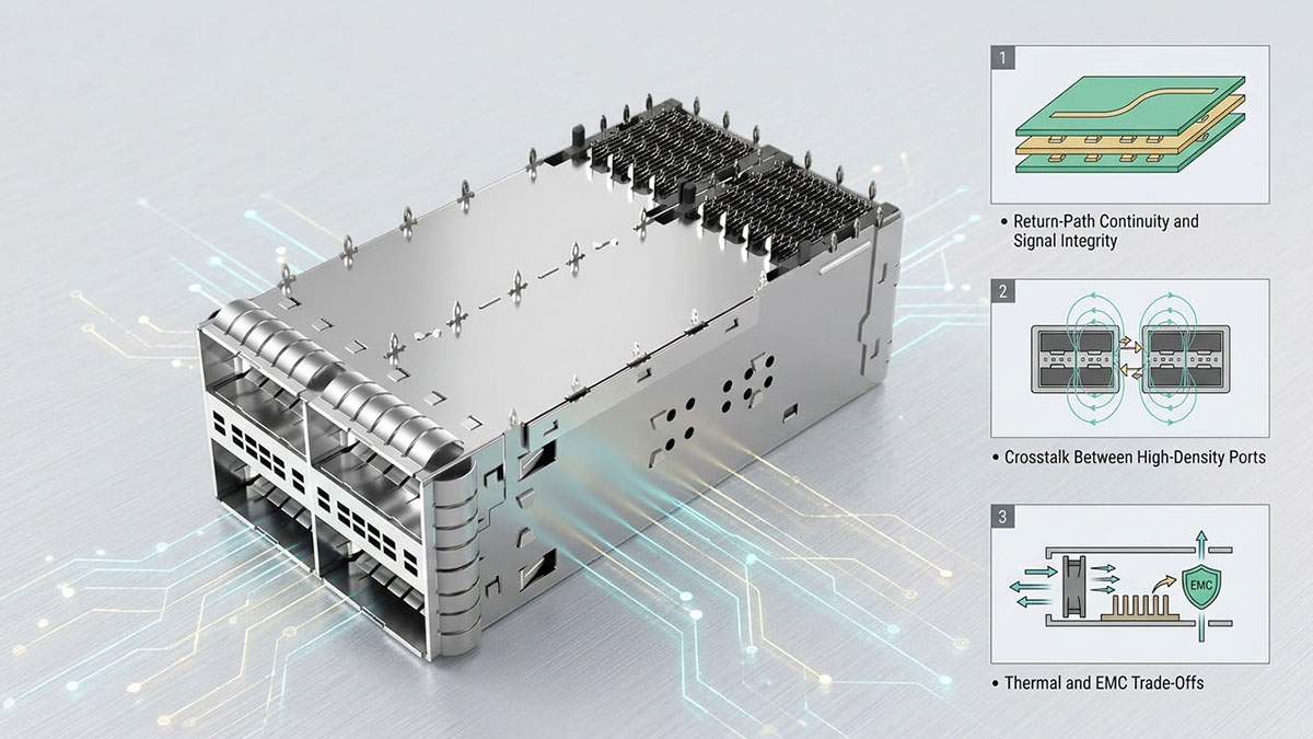
Continuità del percorso di ritorno e integrità del segnale
La continuità del percorso di ritorno è essenziale per l'integrità del segnale 800G, poiché i segnali differenziali ad alta velocità richiedono un ambiente elettromagnetico controllato attorno ai loro percorsi di andata e ritorno. Un assemblaggio di gabbie può influenzare questo ambiente quando la sua struttura conduttiva o l'interfaccia di messa a terra creano discontinuità in prossimità dell'interfaccia tra il connettore e il modulo.
Diversi fattori sono particolarmente importanti:
- Continuità del piano di riferimento: La transizione tra PCB, connettore, gabbia e chassis deve evitare discontinuità non necessarie in corrispondenza delle interfacce ad alta velocità.
- Percorsi di ritorno controllati: Le correnti di ritorno ad alta frequenza dovrebbero seguire percorsi prevedibili anziché essere forzate attorno a strutture meccaniche o intercapedini.
- Messa a terra della gabbia: Un'interfaccia stabile tra la gabbia e il telaio può contribuire a mantenere la schermatura e l'ambiente di riferimento previsti.
- Transizione dei connettori: La transizione elettrica tra il PCB e il modulo ottico deve essere considerata insieme alla struttura della gabbia circostante.
- Geometria fisica: Strutture conduttive inattese in prossimità di tracce ad alta velocità possono alterare la distribuzione locale del campo elettromagnetico.
Un problema di percorso di ritorno può quindi generare due conseguenze contemporaneamente: un'integrità del segnale degradata e un aumento delle interferenze elettromagnetiche (EMI). Ad esempio, quando una corrente ad alta frequenza incontra una discontinuità sfavorevole, parte dell'energia elettromagnetica risultante può accoppiarsi alle strutture conduttive vicine anziché rimanere strettamente associata al percorso del segnale previsto.
Interferenze tra porte ad alta densità
La diafonia diventa sempre più importante man mano che le porte 800G vengono posizionate più vicine, poiché più interfacce elettriche ad alta velocità possono scambiarsi energia elettromagnetica indesiderata attraverso ambienti fisici e conduttivi condivisi. La geometria della gabbia può contribuire a gestire questo accoppiamento controllando la separazione fisica e fornendo confini conduttivi appropriati tra le interfacce adiacenti.
Le considerazioni chiave includono:
- Spaziatura delle porte: La riduzione della distanza aumenta il potenziale di accoppiamento elettromagnetico tra canali adiacenti.
- Geometria della parete della gabbia: Le strutture conduttive interne o esterne possono influenzare l'ambiente di accoppiamento.
- Attività del modulo adiacente: L'utilizzo simultaneo di porte 800G rappresenta una condizione operativa più impegnativa rispetto al test con porte isolate.
- Prossimità dei connettori: I connettori e le tracce del circuito stampato posizionati vicini possono contribuire alla diafonia tra l'estremità vicina e quella lontana.
- Continuità della messa a terra: Una messa a terra inadeguata tra strutture a gabbia adiacenti può creare percorsi di accoppiamento indesiderati.
La gabbia deve quindi essere considerata insieme al layout del PCB e al posizionamento dei connettori. Aumentare la sola separazione meccanica non garantisce una bassa diafonia se la struttura di ritorno elettrico o le interfacce di schermatura rimangono controllate in modo inadeguato.
Compromessi termici e di compatibilità elettromagnetica
In un assemblaggio di gabbia 800G, la gestione termica e le prestazioni EMC possono entrare in conflitto, poiché entrambe dipendono in parte dalla geometria fisica della gabbia e dell'involucro circostante. Aperture più ampie possono facilitare il flusso d'aria e la dissipazione del calore, mentre aperture eccessive o discontinuità possono ridurre il contenimento elettromagnetico.
Questo compromesso può essere valutato attraverso diversi fattori di progettazione:
- Aperture di ventilazione: Migliora il flusso d'aria, ma potrebbe introdurre ulteriori percorsi di dispersione elettromagnetica.
- Densità delle porte: Massimizza la capacità del pannello frontale, ma riduce lo spazio disponibile per le strutture di isolamento.
- Schermatura metallica: Migliora il contenimento elettromagnetico, ma potrebbe influire sul flusso d'aria e sulla complessità meccanica.
- Raffreddamento del modulo: Le ottiche ad alta potenza 800G richiedono percorsi termici efficaci che devono coesistere con le strutture di schermatura.
- Geometria della gabbia: Deve soddisfare contemporaneamente i requisiti di spazio meccanico, termici e di contenimento elettromagnetico.
L'obiettivo non è quindi quello di massimizzare la schermatura, la spaziatura o il flusso d'aria in modo indipendente. Piuttosto, l'assemblaggio della gabbia dovrebbe fornire un'interfaccia bilanciata in cui le prestazioni termiche, l'integrità del segnale e il comportamento EMC rimangano compatibili. In una piattaforma 800G, questo compromesso a livello di sistema è particolarmente importante perché una modifica della gabbia, pensata per risolvere un problema, può inavvertitamente introdurne un altro.
🧾 Errori comuni nella progettazione dell'assemblaggio della gabbia che causano problemi di compatibilità elettromagnetica
Errori comuni nella progettazione degli assemblaggi delle gabbie possono causare problemi di compatibilità elettromagnetica (EMC) quando la gabbia viene valutata solo in termini di accoppiamento meccanico e ritenzione dei moduli, anziché come parte integrante del confine elettromagnetico del sistema. A 800 G, piccole variazioni nella messa a terra, nella geometria dei contatti, nelle aperture o nelle tolleranze meccaniche possono alterare i percorsi di corrente ad alta frequenza e le perdite di interferenze elettromagnetiche (EMI). Questi problemi possono rimanere invisibili durante un'ispezione meccanica di base, ma diventare evidenti durante i test di pre-conformità EMC o i test formali di sistema.
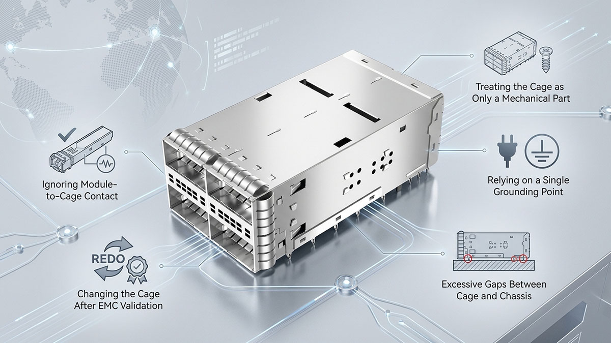
Trattare la gabbia come un semplice componente meccanico
Considerare un gruppo di gabbie esclusivamente come un componente meccanico è uno degli errori di progettazione EMC più elementari, perché trascura il ruolo della gabbia nella schermatura e nella messa a terra. La compatibilità meccanica non garantisce necessariamente un comportamento elettromagnetico equivalente.
Le sviste tipiche includono:
- Valutazione della sola forza di inserimento e ritenzione del modulo.
- Concentrarsi sulla compatibilità dimensionale senza verificare le interfacce conduttive.
- Ignorando la messa a terra tra la gabbia e il telaio.
- Trattare le molle a perno come elementi puramente meccanici.
- Selezione della geometria della gabbia senza considerare le interfacce elettriche ad alta velocità nelle vicinanze.
Una gabbia meccanicamente corretta può quindi comunque creare problemi di compatibilità elettromagnetica (EMC) se le sue superfici conduttive o le interfacce di messa a terra non si integrano correttamente con l'apparecchiatura ospitante. I requisiti di assemblaggio della gabbia dovrebbero includere fin dall'inizio sia le specifiche meccaniche sia i requisiti di interfaccia relativi alla compatibilità elettromagnetica.
Affidarsi a un unico punto di messa a terra
Affidarsi a un singolo punto di messa a terra può creare un percorso sfavorevole per le correnti ad alta frequenza, poiché l'impedenza effettiva di un conduttore aumenta con la frequenza a causa degli effetti induttivi. Una connessione che appare adeguata per la continuità in corrente continua potrebbe quindi non fornire un controllo sufficiente delle correnti ad alta frequenza.
I potenziali problemi includono:
- Percorsi di ritorno della corrente più lunghi.
- Aumento dell'impedenza induttiva.
- Campi elettromagnetici localizzati attorno all'interfaccia di messa a terra.
- Maggiore dipendenza da un unico punto di contatto meccanico.
- Riduzione della continuità della schermatura qualora il contatto diventi inaffidabile.
Ciò non significa che la semplice aggiunta di punti di messa a terra risolva automaticamente un problema di compatibilità elettromagnetica. La loro posizione, geometria, qualità del contatto e integrazione con lo chassis devono essere valutate come parte integrante del percorso completo della corrente RF.
Spazi eccessivi tra gabbia e telaio
Spazi eccessivi tra il gruppo di alloggiamento e lo chassis possono creare percorsi di dispersione RF indesiderati, interrompendo il confine conduttivo attorno all'interfaccia del modulo ottico. Il rischio diventa più rilevante quando gli spazi vuoti si trovano in prossimità di interfacce elettriche ad alta velocità o quando si verificano diverse discontinuità attorno a un pannello frontale densamente popolato.
Le principali fonti di preoccupazione includono:
- Spazi meccanici sovradimensionati.
- Tolleranze incoerenti del telaio o della gabbia.
- Disallineamento durante l'assemblaggio.
- Insufficiente contatto tra molla e contatto.
- Spazi vuoti che rimangono dopo l'inserimento del modulo.
Questi problemi evidenziano perché le dimensioni nominali CAD non sono sufficienti per stabilire le prestazioni EMC. Le condizioni di assemblaggio, inclusi l'accumulo delle tolleranze e la deformazione dei contatti, devono essere considerate quando si valuta l'effettivo confine di schermatura.
Ignorare il contatto tra modulo e gabbia
Ignorare il contatto tra il modulo e l'involucro può compromettere una struttura di schermatura altrimenti ben progettata, poiché il ricetrasmettitore ottico stesso, una volta inserito, diventa parte dell'interfaccia fisica. Qualsiasi spazio indesiderato tra l'alloggiamento del modulo e l'involucro può modificare il confine elettromagnetico attorno alla porta.
Considerazioni importanti includono:
- Geometria dell'alloggiamento: L'involucro del modulo dovrebbe interagire in modo prevedibile con l'apertura della gabbia.
- Pressione di contatto: Il contatto conduttivo deve rimanere stabile nelle condizioni meccaniche previste.
- Variazione di inserzione: Posizioni di inserimento o tolleranze diverse non dovrebbero creare discontinuità di schermatura significative.
- Stato della superficie: Le superfici di contatto devono mantenere caratteristiche elettriche adeguate per tutta la durata di vita prevista.
- Interfacce adiacenti: Nelle configurazioni ad alta densità, gli spazi tra il modulo e l'involucro possono interagire con le porte adiacenti.
Di conseguenza, la validazione dell'assemblaggio del contenitore dovrebbe includere il contenitore con il ricetrasmettitore previsto installato, anziché valutare solo il contenitore vuoto. La combinazione effettiva modulo-contenitore-telaio è ciò che determina il confine elettromagnetico finale.
Sostituzione della gabbia dopo la convalida EMC
La sostituzione del gruppo gabbia dopo la validazione EMC può introdurre comportamenti imprevisti a livello di sistema, poiché anche una gabbia meccanicamente intercambiabile può presentare caratteristiche elettriche ed elettromagnetiche diverse. La sostituzione del materiale della gabbia, della placcatura, dei contatti a molla, della geometria dell'apertura o della struttura di montaggio può modificare l'efficacia della schermatura e i percorsi delle correnti ad alta frequenza.
I cambiamenti potenzialmente significativi includono:
- Diverse dimensioni della gabbia o geometria dell'apertura.
- Diversi materiali conduttivi o trattamenti superficiali.
- Modifiche alla quantità o alla posizione delle dita a molla.
- Punti di contatto modificati tra gabbia e telaio.
- Diverse strutture di montaggio o messa a terra per PCB.
- Variazioni nelle tolleranze di produzione.
Per questo motivo, le modifiche al gruppo gabbia devono essere incluse nel processo di controllo delle modifiche EMC dell'apparecchiatura. Una sostituzione deve essere considerata una modifica di progettazione rilevante ai fini EMC ogniqualvolta modifichi le interfacce conduttive o il confine fisico RF, anche se il modulo ottico rimane meccanicamente compatibile.
🧾 Come scegliere un gruppo gabbia compatibile con EMC per piattaforme da 800G
La scelta di un assemblaggio di gabbia conforme alle normative EMC per una piattaforma 800G richiede ben più che la semplice verifica delle dimensioni del modulo o la selezione di una struttura metallica conduttiva. La gabbia deve integrarsi perfettamente con l'intera interfaccia meccanica, elettrica, di messa a terra e con il telaio, mantenendo al contempo un comportamento EMC prevedibile in base alle tolleranze di produzione e alle condizioni operative. L'approccio di selezione più affidabile prevede quindi la valutazione dell'intera interfaccia, delle prove di compatibilità EMC e della coerenza produttiva prima dell'integrazione della gabbia nel sistema finale.
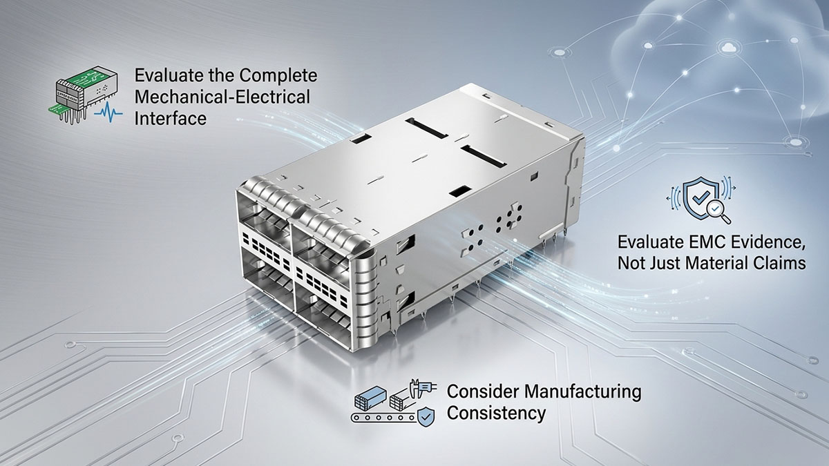
Valutare l'interfaccia meccanico-elettrica completa
Un gruppo gabbia 800G deve essere valutato come un'interfaccia meccanico-elettrica completa, piuttosto che come un componente di montaggio isolato. Le dimensioni meccaniche determinano se il ricetrasmettitore può essere inserito correttamente, mentre le interfacce conduttive determinano l'efficacia con cui la gabbia contribuisce alla schermatura e al controllo della corrente di ritorno ad alta frequenza.
La valutazione dovrebbe riguardare diverse aree interconnesse:
- Dimensioni della gabbia e del modulo: Verificare le dimensioni della gabbia rispetto all'ingombro meccanico previsto per il modulo ottico 800G, inclusi la profondità di inserimento, i dispositivi di ritenzione, la posizione del connettore e i requisiti di spazio libero.
- Montaggio e messa a terra del PCB: Verificare come la gabbia è fissata al PCB e se la sua struttura di montaggio garantisce il collegamento elettrico previsto all'architettura di messa a terra del sistema.
- Integrazione tra telaio e pannello frontale: Valutare l'interfaccia tra la gabbia e il telaio o tra la gabbia e la piastra frontale, inclusi i contatti a molla, le superfici conduttive, i punti di montaggio e l'accumulo delle tolleranze.
- Contatto tra l'alloggiamento del modulo e la gabbia: Verificare che il ricetrasmettitore installato mantenga il rapporto di conduttività previsto con la gabbia laddove la schermatura o la messa a terra dipendano da tale contatto.
- Interazione con la porta adiacente: Nelle configurazioni 800G ad alta densità, valutare la spaziatura e le relazioni fisiche tra gabbie, connettori e moduli adiacenti.
Queste interfacce devono essere esaminate congiuntamente perché un alloggiamento può soddisfare le specifiche meccaniche pur creando un'indesiderata discontinuità RF. Ad esempio, una piccola modifica nella geometria di montaggio può consentire l'inserimento del modulo aumentando al contempo l'impedenza del percorso tra telaio e massa. Allo stesso modo, uno spazio meccanicamente accettabile tra l'alloggiamento e il pannello frontale può diventare un percorso di dispersione EMI alle alte frequenze.
Valutare le prove di compatibilità elettromagnetica, non solo le affermazioni relative ai materiali.
La sola scelta del materiale non è sufficiente a garantire la compatibilità elettromagnetica (EMC) di un assemblaggio di gabbie. Un materiale conduttivo può offrire un buon potenziale di schermatura, ma le effettive prestazioni EMC dipendono anche dalla geometria di messa a terra, dall'integrità dei contatti, dal controllo dell'apertura, dalle tolleranze e dal comportamento della gabbia dopo l'installazione nella piattaforma completa.
Quando si valuta la documentazione relativa alla gabbia o i dati del fornitore, è importante cercare prove che coprano l'intera interfaccia, anziché basarsi solo su affermazioni come "schermatura metallica" o "materiale ad alta conduttività". Le prove pertinenti possono includere:
- Specifiche del materiale conduttivo e del trattamento superficiale
- Progettazione del collegamento a terra tra gabbia e telaio
- Geometria di contatto e informazioni sulla pressione di contatto
- Dati relativi alle tolleranze dimensionali e meccaniche
- Caratteristiche di apertura e di diaframma
- Configurazione di montaggio e messa a terra del PCB
- Informazioni sulla durabilità ambientale o meccanica dei contatti conduttivi
- Risultati dei test EMC o di pre-conformità ottenuti con hardware rappresentativo
Questa distinzione è importante perché l'efficacia della schermatura è una proprietà del sistema. Una gabbia realizzata con una lega altamente conduttiva può comunque avere prestazioni scadenti se i suoi contatti di messa a terra sono discontinui o se ampie aperture incontrollate circondano l'interfaccia ad alta velocità. Al contrario, una gabbia ben progettata può contribuire efficacemente all'architettura EMC quando la sua struttura conduttiva, le interfacce di contatto e le condizioni di installazione sono controllate correttamente.
I dati EMC a livello di componente dovrebbero pertanto essere considerati come prove a supporto, piuttosto che come sostitutivi dei test finali delle apparecchiature. La decisione di selezione più solida deriva dalla correlazione tra le caratteristiche a livello di alloggiamento e l'architettura effettiva della piattaforma 800G e i relativi requisiti EMC previsti.
Considerare la coerenza della produzione
La coerenza produttiva è essenziale perché le prestazioni EMC possono variare quando le dimensioni fisiche o le condizioni di contatto di un gruppo gabbia 800G differiscono da un'unità all'altra. Un progetto che funziona bene in una configurazione di laboratorio potrebbe mostrare un comportamento diverso se le tolleranze di produzione riducono la pressione di contatto, alterano l'allineamento o creano spazi più ampi all'interfaccia con il telaio.
Diversi fattori di produzione meritano particolare attenzione:
- Coerenza dimensionale: Le dimensioni della gabbia, i punti di fissaggio, le aperture e le superfici di accoppiamento devono rimanere entro tolleranze controllate.
- Consistenza del contatto con la molla: Le molle a spirale e gli altri contatti di messa a terra devono mantenere posizione, pressione e innesto prevedibili dopo l'assemblaggio.
- Controllo del processo di assemblaggio: Le fasi di fissaggio del PCB, installazione del telaio, saldatura, serraggio e allineamento non devono alterare involontariamente il percorso di messa a terra previsto.
- Uniformità del trattamento superficiale: La placcatura o altre finiture superficiali devono garantire un contatto conduttivo stabile per tutta la durata prevista di funzionamento.
- Affidabilità dei contatti a lungo termine: Le vibrazioni meccaniche, i cicli termici, l'inserimento e la rimozione, nonché l'esposizione ambientale non devono causare un degrado inaccettabile delle interfacce conduttive.
La validazione della produzione dovrebbe considerare anche l'accumulo delle tolleranze, anziché valutare solo le dimensioni nominali. A densità di porte di 800G, variazioni meccaniche relativamente piccole possono influenzare la distanza tra le superfici conduttive, la continuità dei confini di schermatura e l'impedenza dei percorsi di ritorno ad alta frequenza.
Per questo motivo, un assemblaggio di gabbia conforme ai requisiti EMC non è semplicemente un assemblaggio che offre buone prestazioni come singolo esemplare. Deve garantire un comportamento meccanico ed elettrico sufficientemente ripetibile nell'intera gamma di produzione, in modo che le caratteristiche EMC validate durante la certificazione del sistema rimangano rappresentative dell'hardware di produzione.
🧾 Conclusion
Un assemblaggio di gabbia passiva può diventare un "guardiano nascosto" per la conformità FCC 800G e CE EMC, poiché influenza direttamente il confine conduttivo che circonda le interfacce ad alta velocità. Sebbene la gabbia non contenga componenti elettronici attivi, i suoi percorsi di messa a terra, l'integrità dei contatti, le aperture, il materiale e il trattamento superficiale, le tolleranze meccaniche e l'integrazione con lo chassis possono influenzare il modo in cui l'energia ad alta frequenza viene contenuta, accoppiata e restituita all'interno del sistema.
Le considerazioni principali possono essere riassunte come segue:
- Una gabbia passiva non è necessariamente neutrale dal punto di vista della compatibilità elettromagnetica.
- Una messa a terra continua a bassa impedenza contribuisce a controllare i percorsi di ritorno ad alta frequenza.
- Spazi vuoti e discontinuità di contatto possono creare percorsi di dispersione di interferenze elettromagnetiche indesiderate.
- La geometria della gabbia deve essere valutata insieme all'integrità del segnale 800G e ai requisiti termici.
- La sola compatibilità meccanica non garantisce l'equivalenza EMC.
- Le modifiche alla gabbia devono rimanere soggette al controllo delle modifiche EMC dopo la convalida del sistema.
- La conformità alle normative FCC e CE in materia di compatibilità elettromagnetica dipende in ultima analisi dall'apparecchiatura completa e dalla sua configurazione finale.
Per gli ingegneri che sviluppano o convalidano piattaforme ottiche 800G, trattare l'assemblaggio della gabbia come parte dell'architettura EMC fin dall'inizio può ridurre i problemi di emissioni imprevisti e rendere la certificazione del sistema più prevedibile. Quando si valuta la soluzione di interconnessione ottica più ampia, LINK-PP Negozio ufficiale offre ricetrasmettitori ottici compatibili e prodotti di connettività correlati in grado di supportare i requisiti di implementazione di reti ad alta velocità. La chiave è valutare il modulo ottico, l'alloggiamento, il PCB, lo chassis, la struttura di messa a terra e le interfacce circostanti come un unico sistema integrato, anziché considerare l'alloggiamento passivo come un semplice accessorio meccanico.