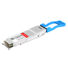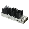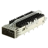
As data centers scale toward higher bandwidth, lower latency, and greater port density, 100G Ethernet has become a foundational building block of modern network architecture. At the center of this transition is QSFP28, a compact, high-performance optical transceiver form factor designed specifically for 100-gigabit data rates.
QSFP28 (Quad Small Form-Factor Pluggable 28) enables 100G transmission by aggregating four parallel 25G electrical lanes, delivering an optimal balance of bandwidth efficiency, power consumption, and deployment flexibility. Compared with legacy 40G QSFP+ modules, QSFP28 provides 2.5× higher throughput within the same physical footprint, making it the dominant choice for spine-leaf data centers, cloud infrastructure, and high-performance computing (HPC) networks.
Despite its widespread adoption, QSFP28 is often misunderstood. It is frequently confused with QSFP+, QSFP56, or older CFP-based 100G solutions. Common questions persist around IEEE standards, optical variants (SR4, LR4, CWDM4), fiber requirements, power budgets, and real-world interoperability across different switch platforms.
What You Will Learn in This Guide
In this article, you will gain a clear, engineering-accurate understanding of QSFP28, including:
-
What QSFP28 is and how it achieves 100G Ethernet
-
Key differences between QSFP28 and related form factors, such as QSFP+ and QSFP56
-
Common QSFP28 module types and their use cases (SR4, LR4, CWDM4, PSM4)
-
Fiber and cabling requirements for short-reach and long-reach deployments
-
Practical deployment considerations, including compatibility, power consumption, and upgrade planning
This guide is written for network engineers, system architects, and technical buyers who need a reliable reference—one that is both technically precise and easy to apply in real-world 100G network design.
➡️ What Is QSFP28 and How It Works
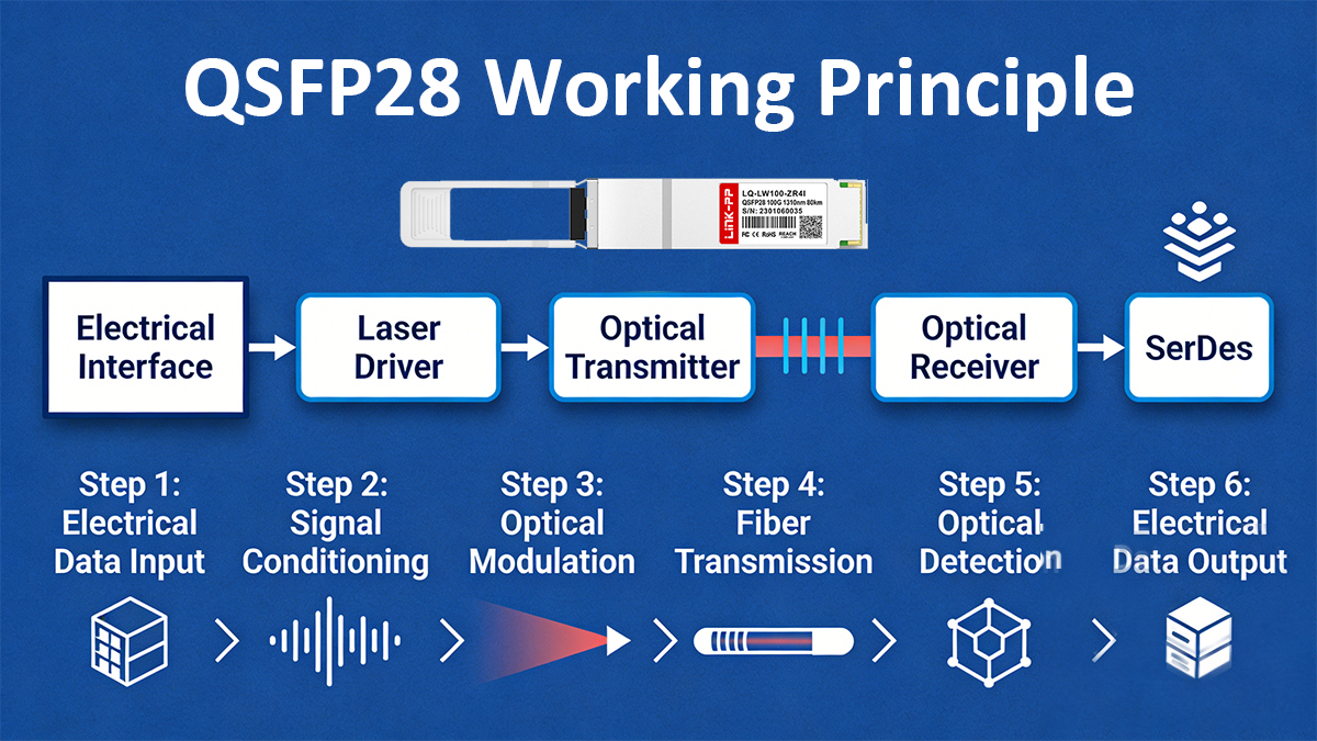
QSFP28 (Quad Small Form-Factor Pluggable 28) is a hot-swappable transceiver form factor designed to support 100 Gigabit Ethernet (100GbE) by utilizing four parallel electrical lanes, each operating at up to 25 Gbps. The “28” in QSFP28 refers to the maximum 28 Gbaud signaling rate per lane, enabling sufficient margin for 25G NRZ modulation after encoding overhead.
From a physical perspective, QSFP28 maintains the same mechanical dimensions and cage interface as QSFP+, allowing network devices to achieve higher bandwidth density without redesigning front-panel layouts. This backward-compatible form factor has been a critical factor in the rapid adoption of QSFP28 across hyperscale data centers and enterprise core networks.
QSFP28 Electrical Architecture
At the electrical interface, QSFP28 relies on four transmit (Tx) and four receive (Rx) differential pairs between the host ASIC and the module. Each lane typically operates at:
-
25.78125 Gbps for Ethernet-based applications (after 64b/66b encoding)
-
NRZ modulation, which remains power-efficient and cost-effective compared to higher-order schemes
This architecture allows QSFP28 to support multiple logical configurations, including:
The standardized electrical interface is defined under IEEE 802.3bm and IEEE 802.3cd, ensuring multi-vendor interoperability at the PHY level.
Optical Signal Transmission in QSFP28
While the electrical side aggregates four lanes, the optical implementation depends on the module type, which determines how signals are transmitted over fiber:
-
Parallel optics (e.g., QSFP28 SR4, PSM4)
Each electrical lane is mapped to a dedicated optical channel, typically over 8-fiber MPO/MTP connectors (4 Tx + 4 Rx).
-
Wavelength-division multiplexing (e.g., QSFP28 LR4, CWDM4)
Four optical wavelengths are multiplexed onto a single-mode duplex LC fiber, reducing fiber count while extending transmission distance.
This flexibility allows QSFP28 to scale from short-reach intra–data center links (≤100 m) to long-reach metro connections (up to 10 km), depending on the optical standard used.
Host-to-Module Communication and Control
QSFP28 modules use the QSFP Management Interface (CMIS / legacy SFF-8636) for:
-
Module identification and capability reporting
-
Digital Optical Monitoring (DOM), including temperature, voltage, laser bias, and optical power
-
Alarm and warning thresholds for proactive network monitoring
These management features are essential for large-scale deployments, where visibility into transceiver health directly impacts network reliability and MTTR (Mean Time to Repair).
Why QSFP28 Is Efficient for 100G Networks
QSFP28 achieves 100G efficiency through a combination of:
-
Lane aggregation instead of higher modulation, reducing DSP complexity
-
Lower power consumption compared to early CFP-based 100G modules
-
High port density, enabling scalable spine–leaf architectures
In practical deployments, QSFP28 modules typically consume 3.5–5 W, depending on optical reach and DSP requirements—significantly lower than legacy 100G solutions.
➡️ QSFP28 vs. QSFP+ vs. QSFP56: Key Differences and Evolution
QSFP+, QSFP28, and QSFP56 represent three successive generations of high-density pluggable transceivers built on the same QSFP mechanical form factor. While they share identical physical dimensions, their electrical signaling rates, modulation methods, and target network roles differ significantly. Understanding these differences is critical for capacity planning, hardware compatibility, and long-term network scalability.
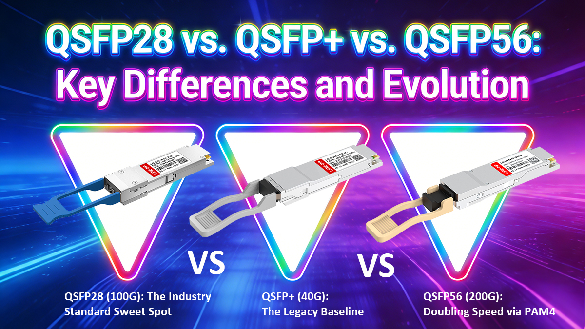
♦ Core Comparison Overview
| Feature |
QSFP+ modules |
QSFP28 modules |
QSFP56 modules |
| Nominal Ethernet Speed |
40G |
100G |
200G |
| Electrical Lanes |
4 |
4 |
4 |
| Per-Lane Signaling |
10.3125 Gbps |
25.78125 Gbps |
50 Gbps |
| Modulation |
NRZ |
NRZ |
PAM4 |
| Typical Use Case |
Legacy 40G |
Mainstream 100G |
Next-gen 200G |
| Power Consumption (typ.) |
2.5–3.5 W |
3.5–5 W |
6–8 W |
| Mechanical Form Factor |
QSFP |
QSFP |
QSFP |
Despite their visual similarity, QSFP56 is not simply a faster QSFP28, and QSFP28 is not a drop-in upgrade from QSFP+ without host-side support.
♦ QSFP+ (40G): The Legacy Baseline
QSFP+ was designed to support 40 Gigabit Ethernet by aggregating four 10G NRZ electrical lanes. Common optical variants include:
QSFP+ played a major role in early spine–leaf data center architectures, but today it is largely considered legacy due to:
-
Limited bandwidth scalability
-
Poor cost-per-bit compared to 100G
-
Reduced ecosystem momentum
While QSFP+ cages are mechanically compatible with newer modules, QSFP+ host hardware cannot support QSFP28 or QSFP56 signaling speeds.
♦ QSFP28 (100G): The Industry Standard Sweet Spot
QSFP28 Transceivers extended the same four-lane architecture to 25G NRZ per lane, enabling 100G Ethernet without increasing lane count. This design delivered a major leap in bandwidth density while preserving:
-
Manageable power consumption
-
High signal integrity margins
-
Broad multi-vendor interoperability
Key reasons QSFP28 became the dominant 100G solution include:
-
Strong alignment with 25G server NICs
-
Mature IEEE standards (802.3bm / 802.3cd)
-
Flexible optical options (SR4, LR4, CWDM4, PSM4)
In practical deployments, QSFP28 supports both native 100G links and breakout configurations (4×25G), making it especially effective in modern data center access and aggregation layers.
♦ QSFP56 (200G): Doubling Speed via PAM4
QSFP56 achieves 200G Ethernet using the same four electrical lanes, but increases per-lane throughput to 50 Gbps by adopting PAM4 modulation instead of NRZ.
This transition introduces several important engineering trade-offs:
-
Higher bandwidth efficiency, but
-
Reduced signal-to-noise margin
-
Increased DSP complexity
-
Higher power consumption and thermal load
QSFP56 is commonly used for:
-
200G leaf–spine interconnects
-
High-performance computing (HPC) fabrics
-
AI / GPU cluster backbones
However, PAM4’s sensitivity to noise means QSFP56 deployments demand higher-quality PCB design, tighter optical budgets, and more rigorous validation than QSFP28.
♦ Compatibility and Upgrade Considerations
A common misconception is that QSFP modules are universally backward compatible. In reality:
-
QSFP28 modules may fit into QSFP+ cages, but will only operate at supported host speeds
-
QSFP56 requires PAM4-capable host ASICs and cannot function in QSFP28-only systems
-
Mechanical compatibility ≠ electrical or protocol compatibility
For network upgrades, this means the transceiver alone cannot define performance—the switch ASIC, firmware, and PHY all play decisive roles.
♦ Which One Should You Choose?
-
Choose 40G QSFP+ only for maintaining or extending legacy 40G networks
-
Choose 100G QSFP28 for cost-effective, stable, and widely supported 100G deployments
-
Choose 200G QSFP56 when 200G bandwidth density is required and the infrastructure is PAM4-ready
For most enterprise and hyperscale networks today, QSFP28 remains the optimal balance of performance, cost, power efficiency, and ecosystem maturity.
➡️ QSFP28 Module Types: (SR4, LR4, CWDM4, PSM4, ER4, ZR4, DR1/FR1,SWDM4, BiDi)
QSFP28 is a family of 100G transceivers that share the same QSFP form factor but use different optical architectures to support varying fiber types, distances, and deployment scenarios.
From a standards perspective, QSFP28 modules fall into IEEE-defined types and MSA or industry-defined variants, each optimized for specific network requirements.
All QSFP28 module types deliver 100G line rate, but differ significantly in fiber count, reach, cost, power consumption, and interoperability, making correct module selection a critical network design decision.
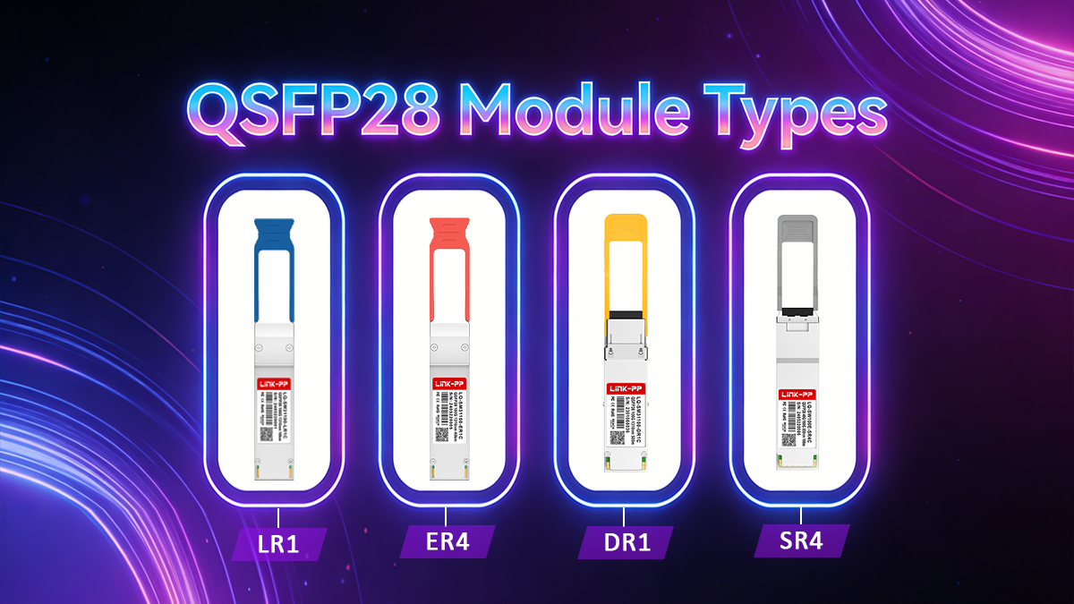
1. IEEE-Standard QSFP28 Module Types
These modules are formally defined by IEEE 802.3 and offer the highest level of cross-vendor interoperability.
QSFP28 SR4 is the standard short-reach solution for multimode fiber (MMF) environments.
Key characteristics:
SR4 is widely deployed inside data centers for intra-rack and inter-rack connectivity, where high port density and low cost per bit are priorities.
Design trade-off:
Requires parallel fiber cabling (8 active fibers), which increases fiber count but minimizes module complexity and power consumption.
QSFP28 LR4 is the IEEE-defined long-reach solution for single-mode fiber (SMF).
Key characteristics:
LR4 significantly reduces fiber usage compared to SR4 and is commonly used for:
Design trade-off:
Higher cost and power consumption compared to SR4, due to WDM optics and tighter wavelength control.
2. MSA and Industry-Defined QSFP28 Variants
To address cost efficiency, fiber scarcity, or extended reach, the industry has introduced several non-IEEE but widely adopted QSFP28 variants.
QSFP28 CWDM4 — Cost-Optimized Duplex SMF
CWDM4 is an MSA-defined alternative to LR4, designed for shorter single-mode links.
Key characteristics:
CWDM4 reduces optical complexity and cost compared to LR4, making it popular in hyperscale data centers where distances are limited but fiber efficiency is still important.
QSFP28 PSM4 — Parallel Single-Mode Architecture
PSM4 uses parallel optics over single-mode fiber, similar in topology to SR4 but with longer reach.
Key characteristics:
PSM4 avoids wavelength multiplexing, which simplifies optics but requires parallel SMF cabling. It is most suitable for data centers already standardized on MPO-based SMF infrastructure.
For applications beyond 10 km, extended-reach QSFP28 variants are available:
These modules are used in metro, carrier, and long-haul enterprise networks, where reach is prioritized over cost and power efficiency.
Newer QSFP28 designs use single-wavelength PAM4 modulation to deliver 100G over fewer optical lanes.
Benefits include:
These modules are increasingly relevant in next-generation architectures, though interoperability and ecosystem maturity vary by implementation.
Both are niche but valuable solutions in fiber-constrained upgrade scenarios.
3. QSFP28 Module Type Comparison Summary
| Module Type |
Fiber |
Reach |
Optical Method |
Connector |
Standard |
| SR4 |
MMF |
70–150 m |
Parallel |
MPO-12 |
IEEE |
| LR4 |
SMF |
10 km |
WDM |
LC |
IEEE |
| CWDM4 |
SMF |
~2 km |
CWDM |
LC |
MSA |
| PSM4 |
SMF |
0.5–2 km |
Parallel |
MPO-12 |
MSA |
| ER4 |
SMF |
~40 km |
WDM |
LC |
Extended |
| ZR4 |
SMF |
80 km+ |
WDM |
LC |
Proprietary / MSA |
| DR1 / FR1 |
SMF |
varies |
Single-lambda PAM4 |
LC |
MSA |
| SWDM4 |
MMF |
~75–150 m |
SWDM |
LC |
MSA |
| BiDi |
SMF/MMF |
varies |
Bidirectional |
LC simplex |
MSA |
➡️ Fiber and Cabling Requirements for QSFP28
QSFP28 transceivers deliver 100G Ethernet through very different fiber and cabling architectures, depending on the module type. While the electrical interface to the host remains consistent, fiber selection, connector type, and polarity management vary significantly and are frequent sources of deployment errors.
Understanding QSFP28 fiber and cabling requirements is therefore essential for performance stability, interoperability, and long-term scalability.
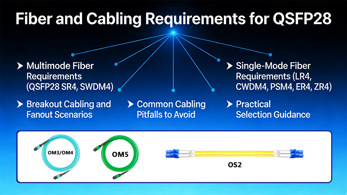
▶ Multimode Fiber Requirements (QSFP28 SR4, SWDM4)
QSFP28 SR4 — Parallel Multimode Cabling
100G-SR4 uses parallel optics over multimode fiber (MMF) and requires MPO-based cabling.
Key requirements:
Engineering considerations:
-
Polarity must be carefully managed end-to-end
-
Poor-quality MPO connectors significantly degrade link margin
-
SR4 links cannot be extended with patch panels designed for duplex LC
SR4 is ideal for high-density data center environments, but it requires strict MPO hygiene and cable management discipline.
QSFP28 SWDM4 — Duplex Multimode Alternative
100G SWDM4 allows 100G over duplex MMF, avoiding MPO cabling.
Key requirements:
-
Fiber type: OM3 / OM4 / OM5
-
Connector: Duplex LC
-
Wavelengths: Multiple short wavelengths over MMF
-
Reach: typically 75–150 m
Trade-offs:
-
Higher module cost compared to SR4
-
Less standardized across vendors
-
Lower availability than SR4
SWDM4 is best used when existing duplex MMF cabling must be reused.
▶ Single-Mode Fiber Requirements (LR4, CWDM4, PSM4, ER4, ZR4)
100G-LR4 and CWDM4 — Duplex SMF Cabling
LR4 and CWDM4 transmit four 25G lanes using wavelength-division multiplexing (WDM) over duplex single-mode fiber.
Key requirements:
Engineering considerations:
-
Fiber cleanliness is critical at longer distances
-
Mixing LR4 and CWDM4 modules on the same link is not recommended
-
Attenuators may be required for short links to avoid receiver overload
These modules provide excellent fiber efficiency and are common in campus and DCI-lite deployments.
QSFP28 PSM4 — Parallel Single-Mode Cabling
100G PSM4 uses parallel SMF, similar in topology to SR4 but with longer reach.
Key requirements:
Engineering considerations:
-
Requires MPO-based SMF infrastructure
-
Simpler optics (no WDM) but higher fiber count
-
Often used in large-scale data centers with structured parallel cabling
Extended Reach (ER4 / ZR4) — Long-Haul SMF
For distances beyond 10 km, extended-reach QSFP28 modules impose strict optical and cabling constraints.
Key requirements:
Engineering considerations:
-
Often require optical amplification or dispersion management
-
Sensitive to connector loss and fiber aging
-
Typically validated per-link, not assumed
▶ Breakout Cabling and Fanout Scenarios
QSFP28 also supports breakout configurations, most commonly:
Common breakout options:
-
MPO-to-4×LC fanout (SR4 / PSM4)
-
Active optical cables (AOC)
-
Direct attach copper (DAC) for short distances
Critical requirement:
Breakout only works when both the QSFP28 port and the host system explicitly support 4×25G mode.
▶ Common Cabling Pitfalls to Avoid
-
Assuming MPO polarity is “plug-and-play”
-
Mixing WDM-based and parallel-optic modules
-
Reusing legacy OM2 fiber for 100G links
-
Ignoring insertion loss budgets in short links
-
Overlooking firmware and port breakout configuration
▶ Practical Selection Guidance
| Deployment Scenario |
Recommended Cabling |
| Intra-rack / inter-rack DC |
OM4 + QSFP28 SR4 |
| Existing duplex MMF |
SWDM4 |
| Campus / building-to-building |
OS2 + LR4 |
| Cost-sensitive SMF DC |
CWDM4 |
| Parallel SMF DC |
PSM4 |
| Metro / long reach |
ER4 / ZR4 |
Engineering Takeaway
QSFP28 performance is only as reliable as the fiber and cabling system behind it. Correct fiber type, connector choice, polarity control, and optical budgeting are not optional—they define whether a 100G link is stable, scalable, and supportable over time.
➡️ QSFP28 Modules Compatibility, Standards, and Interoperability Risks
QSFP28 transceivers are often perceived as “plug-and-play” components because they share a common form factor. In reality, mechanical compatibility does not guarantee electrical, optical, or protocol interoperability. Most QSFP28 deployment issues stem from misunderstandings around standards compliance, host capabilities, and vendor-specific implementations.
This section clarifies how QSFP28 compatibility really works—and where the hidden risks lie.
☆ QSFP28 Standards Landscape: IEEE vs MSA vs Vendor Specs
Understanding QSFP28 interoperability starts with recognizing three different specification layers:
-
IEEE Ethernet Standards (Authoritative Baseline)
-
MSA (Multi-Source Agreement) Specifications
-
Vendor-Specific Extensions
-
Proprietary reach extensions (e.g., “ZR+”)
-
Custom firmware tuning
-
Often optimized for specific platforms
-
Highest risk of lock-in and incompatibility
Key takeaway:
IEEE-compliant QSFP28 modules are the safest choice for heterogeneous networks. MSA-based modules require stricter validation, while proprietary variants should be deployed cautiously.
☆ Host Compatibility: The Most Common Failure Point
A QSFP28 module’s performance is constrained by the switch ASIC, PHY, and firmware, not the transceiver alone.
Common misconceptions include:
-
❌ “QSFP28 fits in the port, so it will run at 100G”
-
❌ “QSFP56 ports always support QSFP28 automatically”
Reality:
-
QSFP28 requires 25G NRZ electrical lanes on the host side
-
QSFP+ (40G) hosts cannot support QSFP28 at full rate
-
QSFP56 hosts may support QSFP28, but only if explicitly enabled in hardware and firmware
Additionally, features such as breakout (4×25G) depend entirely on host port configuration and ASIC support.
☆ Backward and Forward Compatibility Limits
| Scenario |
Supported? |
Explanation |
| QSFP28 module in QSFP28 port |
✅ Yes |
Native support |
| QSFP28 module in QSFP+ port |
❌ No (100G) |
Electrical lanes limited to 10G |
| QSFP28 module in QSFP56 port |
⚠️ Conditional |
Requires host support |
| QSFP56 module in QSFP28 port |
❌ No |
PAM4 not supported |
| QSFP28 DAC/AOC vs optical mix |
⚠️ Limited |
Power and signal constraints |
Mechanical fit ≠ functional compatibility is the most critical rule in QSFP ecosystems.
☆ Optical Interoperability Risks
Even when speeds and standards appear aligned, optical mismatches can break links:
-
Mixing LR4 with CWDM4 on the same fiber pair
-
Pairing mismatched BiDi wavelengths
-
Using ER4/ZR4 modules without validating fiber attenuation and dispersion
-
Receiver overload on short links without attenuation
Small deviations in wavelength accuracy or power budget can result in intermittent errors, not immediate link failure—making diagnosis difficult.
☆ Firmware Locking and Vendor Coding
Many switch vendors implement EEPROM-based transceiver authentication, which can block or limit third-party QSFP28 modules.
Typical symptoms include:
-
Module detected but link remains down
-
DOM/DDM information unavailable
-
Power capped or lanes disabled
Mitigation strategies:
-
Use standards-compliant optics
-
Validate firmware compatibility in advance
-
Work with vendors offering multi-vendor coded or programmable QSFP28 modules
☆ Interoperability Best Practices (Engineering Checklist)
To minimize QSFP28 compatibility risks:
-
Prefer IEEE-standard module types where possible
-
Validate host ASIC support (not just port type)
-
Match optical architecture end-to-end
-
Test breakout modes explicitly
-
Avoid mixing MSA and proprietary optics in critical links
-
Perform lab validation before large-scale deployment
QSFP28 interoperability is governed by standards alignment, host capability, and optical discipline—not by form factor alone. Networks that treat QSFP28 as a commodity component often encounter avoidable downtime, while well-validated deployments achieve long-term stability and upgrade flexibility.
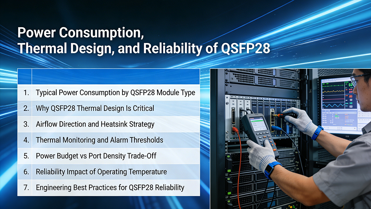
➡️ Power Consumption, Thermal Design, and Reliability of QSFP28
At 100G line rates, power and thermal behavior are no longer secondary considerations—they directly determine link stability, port density, and hardware lifespan. QSFP28 reliability is fundamentally shaped by how well electrical efficiency, heat dissipation, and operating margins are managed at the system level.
1. Typical Power Consumption by QSFP28 Module Type
QSFP28 power draw varies significantly depending on optical architecture and reach:
| QSFP28 Type |
Typical Power |
Thermal Impact |
| 100GBASE-SR4 |
~3.0–3.5 W |
Low |
| 100G CWDM4 |
~3.5–4.0 W |
Medium |
| 100G PSM4 |
~3.5–4.0 W |
Medium |
| 100GBASE-LR4 |
~4.5–5.0 W |
High |
| 100G ER4 / ZR4 |
5.5–6.5 W |
Very High |
Key insight:
Every additional watt at the transceiver level multiplies into rack-level thermal density, often becoming the limiting factor in high-port-count switches.
2. Why QSFP28 Thermal Design Is Critical
Unlike lower-speed optics, QSFP28 100G modules integrate:
-
Multi-lane DSP or gearbox ICs
-
High-speed laser drivers and TIAs
-
On-module monitoring and control logic
This creates localized heat hotspots near the module nose and electrical connector, which can lead to:
-
Laser wavelength drift
-
Reduced receiver sensitivity
-
Increased bit error rate (BER)
-
Premature component aging
Thermal stress is cumulative and often manifests as intermittent link instability rather than immediate failure.
3. Airflow Direction and Heatsink Strategy
QSFP28 modules are designed to work with specific airflow assumptions:
Mismatch between module orientation and system airflow can raise case temperature by 10–15°C, even if total airflow volume is sufficient.
Best practices include:
-
Selecting QSFP28 variants optimized for system airflow
-
Using enhanced heatsinks for ≥4.5 W modules
-
Avoiding dense deployment of high-power optics in adjacent ports
4. Thermal Monitoring and Alarm Thresholds
Most QSFP28 modules support DOM/DDM telemetry, including:
-
Module temperature
-
Supply voltage
-
Laser bias current
-
Optical TX/RX power
However, temperature alarm thresholds vary by vendor and are often conservative.
Engineering guidance:
-
Maintain case temperature at least 10°C below maximum rating
-
Treat warning alarms as action items, not noise
-
Correlate temperature trends with error counters and FEC statistics
Proactive monitoring prevents cascading failures during peak traffic or cooling degradation events.
5. Power Budget vs. Port Density Trade-Off
High-density switches (32×100G, 64×100G, 128×100G) impose strict aggregate power limits per line card.
Typical constraints:
Exceeding these limits may result in:
This is why many hyperscale deployments favor SR4, DR1, or CWDM4 over LR4 whenever fiber topology allows.
6. Reliability Impact of Operating Temperature
QSFP28 reliability follows classic semiconductor behavior:
Modules that pass initial acceptance testing may still fail prematurely if operated near thermal limits continuously.
Long-term reliability is achieved by margin—not by maximum compliance.
7. Engineering Best Practices for QSFP28 Reliability
To maximize operational stability:
-
Match module power class to switch thermal design
-
Avoid mixing low- and high-power optics in the same port group
-
Validate airflow and heatsink compatibility
-
Monitor DOM trends, not just absolute values
-
Plan optics selection alongside rack cooling strategy
QSFP28 optics succeed or fail based on thermal discipline, not headline specifications. Power-efficient architectures, airflow-aware deployment, and proactive monitoring together determine whether 100G links remain stable for years—or become chronic trouble tickets.
➡️ Common 100G QSFP28 Issues and Troubleshooting Guide
Despite standardization, QSFP28 deployments frequently encounter link instability, interoperability warnings, or unexpected performance degradation. Most issues are not caused by defective optics, but by architecture mismatches, thermal constraints, or configuration assumptions.
This guide summarizes the most common QSFP28 problems seen in production networks and provides engineering-grade troubleshooting paths.
Issue 1: QSFP28 Link Does Not Come Up
Typical symptoms
-
Interface remains down after insertion
-
No light detected or LOS asserted
-
Port stays administratively up but operationally down
Root causes
-
Module type mismatch (e.g., SR4 vs LR4)
-
Incorrect fiber type or polarity
-
Breakout configuration mismatch
-
Incompatible FEC settings
Troubleshooting steps
-
Verify module standard on both ends (SR4 ↔ SR4, LR4 ↔ LR4)
-
Confirm fiber type and connector (MPO vs LC)
-
Check polarity (especially for SR4 / PSM4)
-
Validate FEC mode matches link standard
Engineering solution
Standardize link templates and validate optics/fiber mapping during design—not after deployment.
Issue 2: Intermittent Link Flaps or CRC Errors
Typical symptoms
Root causes
-
Marginal optical power budget
-
Dirty or damaged fiber connectors
-
Excessive temperature near module limits
Troubleshooting steps
-
Check TX/RX optical power via DOM
-
Inspect and clean connectors (especially MPO ferrules)
-
Monitor module temperature under traffic load
-
Review FEC statistics for sustained correction events
Engineering solution
Operate links with at least 3 dB optical margin and keep module temperature ≥10°C below maximum rating.
Issue 3: High Temperature Alarms or Port Shutdowns
Typical symptoms
-
DOM temperature warning or alarm
-
Port disabled by switch protection logic
-
Gradual performance degradation
Root causes
-
High-power optics in dense port groups
-
Inadequate airflow direction or obstruction
-
Mismatch between optics power class and switch thermal design
Troubleshooting steps
-
Compare actual module power vs switch port budget
-
Validate airflow direction (front-to-back vs back-to-front)
-
Check heatsink presence and orientation
-
Measure temperature delta between adjacent ports
Engineering solution
Avoid clustering ≥4.5 W optics and deploy enhanced heatsinks where required.
Issue 4: Incompatibility or Vendor Lock Warnings
Typical symptoms
-
“Unsupported transceiver” message
-
Reduced functionality or disabled DOM
-
Firmware warnings after optics insertion
Root causes
Troubleshooting steps
-
Verify switch firmware compatibility matrix
-
Confirm module follows QSFP28 MSA EEPROM layout
-
Test optics on multiple platforms if possible
Engineering solution
Use vendor-neutral optics tested against target platforms and maintain firmware alignment across network layers.
Issue 5: Breakout Links Fail or Only Some Lanes Work
Typical symptoms
Root causes
Troubleshooting steps
-
Confirm switch supports the breakout configuration
-
Verify cable type and length
-
Check lane mapping documentation
-
Inspect per-lane DOM data
Engineering solution
Treat breakout links as distinct architectures, not as simple cable changes.
Issue 6: Unexpected Short Reach or Power Budget Failure
Typical symptoms
-
Link unstable well below rated distance
-
RX power near sensitivity limit
-
Frequent FEC intervention
Root causes
-
Fiber attenuation higher than assumed
-
Excessive patch panel or connector loss
-
Wrong fiber grade (OM3 vs OM4)
Troubleshooting steps
-
Measure end-to-end fiber loss
-
Count connectors and splices
-
Validate fiber grade against module spec
Engineering solution
Design optical paths with conservative loss assumptions and verify physical layer during acceptance testing.
Issue 7: QSFP28 Modules Fail After Initial Deployment
Typical symptoms
Root causes
-
Sustained high operating temperature
-
Continuous operation near optical limits
-
Inadequate environmental monitoring
Troubleshooting steps
-
Review historical DOM trends
-
Correlate failures with temperature spikes
-
Compare failure rates by rack or airflow zone
Engineering solution
Reliability depends on operating margin, not spec compliance alone.
Quick Troubleshooting Checklist
-
✅ Match module standards end-to-end
-
✅ Verify fiber type, polarity, and loss budget
-
✅ Align FEC and breakout configuration
-
✅ Monitor temperature trends, not just alarms
-
✅ Avoid dense deployment of high-power optics
➡️ QSFP28 Modules Deployment Summary and Engineering Recommendations
QSFP28 has become the workhorse interface for 100G Ethernet, striking a practical balance between bandwidth density, power efficiency, and ecosystem maturity. From hyperscale data centers to enterprise backbones and 5G transport networks, QSFP28 enables scalable 100G deployments without the cost and thermal penalties of earlier generations—or the early-adopter risks of newer ones.
Key Takeaways
-
QSFP28 = 100G done right
Based on four 25G lanes (NRZ), QSFP28 delivers stable 100G performance with well-understood signal integrity, mature FEC support, and broad vendor interoperability.
-
Module choice matters more than form factor
SR4, LR4, CWDM4, and PSM4 are not interchangeable. Fiber type, reach, connector density, and operational model must drive selection—not just headline distance.
-
Compatibility is a system-level concern
True reliability depends on alignment across optics, switch ASICs, firmware, cabling, airflow, and thermal design. QSFP28 failures are usually integration issues, not optical defects.
-
Thermal and power margins define long-term reliability
Running modules well below maximum power and temperature ratings significantly improves lifespan and reduces silent degradation.
-
QSFP28 remains future-proof for most 100G needs
Even as QSFP56 and 400G interfaces expand, QSFP28 continues to offer the best cost-to-performance ratio for stable, large-scale 100G networks.
Final Engineering Recommendations
-
Design first, deploy second
Validate fiber loss budgets, connector counts, airflow direction, and breakout requirements during the design phase.
-
Standardize optics profiles
Limit the number of QSFP28 module types per environment to reduce operational complexity and troubleshooting time.
-
Monitor trends, not just alarms
Track DOM metrics—especially temperature and optical power—over time to catch degradation early.
-
Test interoperability before scale-out
Lab validation across target switch platforms prevents costly surprises in production.
If you are planning or upgrading a 100G QSFP28 deployment, LINK-PP provides:
-
✅ Vendor-neutral QSFP28 transceivers (SR4, LR4, CWDM4, PSM4)
-
✅ Proven compatibility testing across mainstream switch platforms
-
✅ Engineering support for module selection, thermal planning, and validation
-
✅ Sample testing and fast global delivery
? Visit the LINK-PP Official Store to request samples, compatibility reports, or engineering consultation for your QSFP28 network design.