
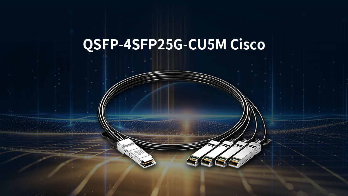
The QSFP-4SFP25G-CU5M is a cornerstone of high-density Cisco networking, enabling the seamless breakout of a single 100G QSFP28 port into four discrete 25G SFP28 channels. As data centers migrate toward 100G architectures, this passive Direct Attach Copper (DAC) cable offers a cost-effective, low-latency solution for Top-of-Rack (ToR) switches to interconnect with downstream servers and storage arrays.
However, the 5-meter length of the QSFP-4SFP25G-CU5M represents the absolute physical frontier for passive copper transmission at 25G per lane. While it provides maximum reach without the power consumption of optical transceivers, it operates at the edge of signal integrity limits. Understanding the balance between its deployment flexibility and the technical risks of attenuation and bit error rates is vital for maintaining robust network performance.
🌱 Understanding the Role of QSFP-4SFP25G-CU5M in High-Density Networks
The QSFP-4SFP25G-CU5M serves as a vital bridge in modern data centers, allowing high-bandwidth switches to communicate efficiently with multiple lower-speed endpoints. By splitting a single high-capacity port into four distinct lanes, it optimizes port density and reduces the overall cost of network hardware.
What is the Cisco QSFP-4SFP25G-CU5M Breakout Cable
The Cisco QSFP-4SFP25G-CU5M is a passive Direct Attach Copper (DAC) breakout cable designed for high-speed data transmission. It features one QSFP28 connector on one end and four 25G SFP28 connectors on the other, enabling a 100G-to-25G "breakout" configuration.
Because it is a passive cable, it contains no active electronic components to amplify the signal. This makes it an incredibly energy-efficient and low-latency choice for short-range connections within a single rack or between adjacent racks.
Key Technical Specifications and Form Factors
This DAC cable supports a total aggregate bandwidth of 100Gbps, with each of the four breakout branches delivering a dedicated 25Gbps lane. It utilizes high-quality twinaxial copper wiring, which is shielded to maintain signal integrity across its 5-meter span.
The form factor is fully compliant with SFF-8665 and SFF-8402 standards, ensuring it fits perfectly into standard Cisco Nexus and Catalyst ports. To support the 5-meter distance, these cables typically use a thicker wire gauge (such as 26AWG or 24AWG) to minimize electrical resistance.
Common Deployment Scenarios: Top-of-Rack (ToR) to Server Interconnects
The most frequent use case for the QSFP-4SFP25G-CU5M is connecting a Top-of-Rack (ToR) switch to multiple servers or storage appliances. It allows a single 100G switch port to support four separate servers, significantly increasing the number of devices a single switch can manage.
This setup is ideal for virtualization environments and high-frequency trading platforms where low latency is a priority. By using a breakout cable instead of individual transceivers, data center managers can simplify cabling complexity and reduce the physical footprint of their infrastructure.
Why the 5-Meter Length is a Critical Threshold for Copper Passive DACs
In the world of 25G networking, 5 meters is widely considered the maximum reliable limit for passive copper transmission. Beyond this distance, the high-frequency signals required for 25Gbps data rates begin to degrade rapidly due to electrical attenuation.
While shorter DACs (1m to 3m) are common, the 5m version provides the extra reach needed to span across multiple racks in a large data center. However, reaching this distance requires precision engineering, as the signal-to-noise ratio becomes much tighter at the 5-meter boundary.
🌱 Physical Performance Audit: Where QSFP-4SFP25G-CU5M Excels
The QSFP-4SFP25G-CU5M is purpose-built to uphold rigorous physical standards, ensuring reliable performance even at its maximum 5-meter reach. Its robust build quality is essential for maintaining stable data transmission while navigating the demanding mechanical stresses typical of high-density data center environments.
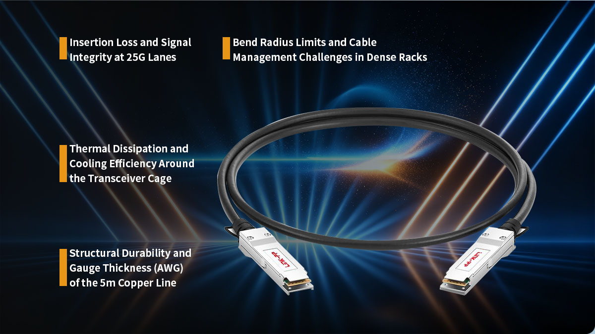
Insertion Loss and Signal Integrity at 25G Lanes
At 25G speeds, maintaining signal clarity is a major challenge because high-frequency signals tend to weaken quickly. The QSFP-4SFP25G-CU5M is designed with premium shielding and precision termination to keep insertion loss within acceptable IEEE 802.3 standards.
By minimizing signal reflection and electrical noise, this cable ensures that each of the four 25G lanes remains distinct and stable. This level of signal integrity is crucial for preventing data corruption as the signal travels the full 5-meter length of the copper wire.
Bend Radius Limits and Cable Management Challenges in Dense Racks
Because 5-meter DACs use thicker internal wiring, they are naturally stiffer than shorter cables. It is essential to respect the minimum bend radius to avoid damaging the internal copper pairs, which could lead to permanent signal degradation or link failure.
In dense server racks, managing these longer, heavier cables requires proper support like horizontal cable managers or Velcro ties. Ensuring the cables aren't kinked or tightly coiled helps maintain the physical geometry of the internal wires, which is vital for high-speed performance.
Thermal Dissipation and Cooling Efficiency Around the Transceiver Cage
One of the biggest advantages of the passive QSFP-4SFP25G-CU5M is that it consumes zero power and generates no heat of its own. This is a significant benefit in high-density switch environments where keeping the transceiver cage cool is a constant struggle.
By using passive DACs, the overall thermal load on the switch is reduced compared to using optical transceivers. This allows for better airflow through the chassis and helps ensure that the switch operates within its optimal temperature range.
Structural Durability and Gauge Thickness (AWG) of the 5m Copper Line
To achieve a reliable 5-meter reach at 25Gbps, the QSFP-4SFP25G-CU5M typically utilizes a thicker 24AWG or 26AWG wire gauge. This extra thickness reduces electrical resistance and allows the high-speed signal to travel further without disappearing into background noise.
The heavy-duty jacket and reinforced strain relief at the connector ends provide the structural durability needed for frequent handling. This robust construction ensures that the cable can survive the rigors of installation and long-term use in a busy enterprise environment.
🌱 The Technical Boundaries: When QSFP-4SFP25G-CU5M Reaches Its Signal Limits
Deploying the QSFP-4SFP25G-CU5M requires a clear understanding of the physical boundaries of passive copper. At a length of 5 meters, high-frequency electrical signals operate at the absolute margin of stability. Pushing past these performance thresholds can lead to immediate link degradation and packet loss.
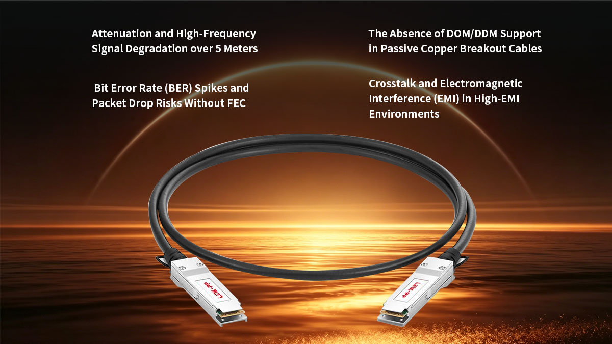
Attenuation and High-Frequency Signal Degradation over 5 Meters
As data rates climb to 25Gbps per lane, the electrical signal attenuates, or weakens, drastically over copper medium. At this high frequency, the skin effect and dielectric losses absorb the signal energy before it can reach the receiving port. This rapid degradation is the primary reason why passive copper breakout technology cannot reliably exceed the 5-meter mark.
To illustrate how distance impacts performance, the following table outlines the correlation between cable length and signal degradation characteristics for passive 25G lanes:
| Cable Length (Meters) |
Typical Gauge (AWG) |
Signal Attenuation Level |
Risk of Link Instability |
| 1m - 3m |
30 AWG / 28 AWG |
Low |
Negligible |
| 5m |
26 AWG / 24 AWG |
High (Borderline Limit) |
Moderate (Requires FEC) |
| > 5m |
N/A |
Critical Failure |
High (Link Drop) |
Bit Error Rate (BER) Spikes and Packet Drop Risks Without FEC
At the 5-meter threshold, the signal-to-noise ratio drops significantly, which naturally causes the Bit Error Rate (BER) to rise. Without proper mitigation, these bit errors lead to corrupted frames, forcing switches to drop packets and retransmit data. This issue can severely cripple application throughput and increase overall network latency.
To counter this, Forward Error Correction (FEC) must be explicitly enabled on the host switch ports. FEC works by adding redundant error-checking bits to the data stream, allowing the receiving switch to identify and correct minor errors instantly without dropping the packet.
The Absence of DOM/DDM Support in Passive Copper Breakout Cables
Unlike active optical transceivers, the QSFP-4SFP25G-CU5M does not include internal microchips for Digital Optical Monitoring (DOM) or Digital Diagnostics Monitoring (DDM). Because the cable is completely passive, it cannot report real-time telemetry metrics such as temperature, voltage, or laser power.
This lack of visibility makes proactive troubleshooting much more difficult for network engineers. Without DOM data, you cannot monitor the precise health of the physical link, forcing you to rely strictly on basic port status logs and error counters on the switch CLI.
Crosstalk and Electromagnetic Interference (EMI) in High-EMI Environments
In crowded data center environments, cables are often packed tightly together, increasing the risk of crosstalk between adjacent copper pairs. The high-frequency signals running through each of the four 25G channels can bleed into one another if the cable shielding is compromised or bent too aggressively.
Additionally, external Electromagnetic Interference (EMI) from nearby power lines or cooling fans can distort the delicate signals over a 5-meter run. Proper spacing and high-quality shielding are necessary to keep the signal isolated and prevent external noise from disrupting data flow.
🌱 Compatibility Validation for QSFP-4SFP25G-CU5M Across Cisco Platforms
Ensuring hardware compatibility is a vital step before deploying the QSFP-4SFP25G-CU5M in a live environment. Cisco platforms require strict validation to recognize the passive breakout cable and handle the 100G-to-25G split properly. Verifying the hardware matrix and software commands prevents unexpected port shutdowns or configuration errors.
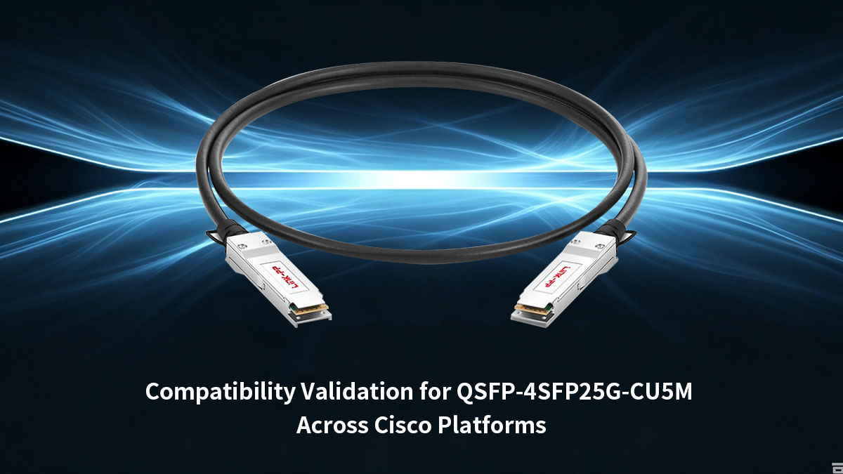
Cisco Nexus Switch Series Support Matrix
The QSFP-4SFP25G-CU5M is widely supported across the Cisco Nexus data center portfolio, particularly within the Nexus 9000 series. However, not every 100G QSFP28 port on these switches is capable of breaking out into four 25G channels.
Network engineers must consult the official Cisco Optics Compatibility Matrix to verify specific line cards and port mappings. Some older hardware revisions may only support standard 100G direct connections, meaning they lack the internal architecture required to manage a 4x25G split on that specific interface.
Host Stream Port Configuration: 100G Breakout to 4x 25G Channelization
To activate the cable, the host 100G port must be manually reconfigured to support channelization. By default, the switch treats a QSFP28 port as a single 100Gbps pipe, so inserting a breakout cable without changing the port mode will result in a link failure.
Using the appropriate CLI command splits the physical port into four logical, independent 25G sub-interfaces. Once channelized, each 25G SFP28 branch can be configured with its own VLANs, routing protocols, and security policies just like a standard standalone port.
Operating System Verification: NX-OS and Cisco IOS-XR Command Lines
Depending on your specific network architecture, you will use either Cisco NX-OS or Cisco IOS-XR to configure and verify the breakout connection. In NX-OS, administrators use the global configuration command “interface breakout slot/port map 25g-4x” to split the physical 100G interface into four distinct 25G channels.
Once the hardware recognizes the split, you can verify the status of the new sub-interfaces by running the “show interface status” command. This allows you to confirm that all four 25G lanes are initialized properly, showing an active "connected" state with the correct speed and duplex settings.
🌱 Troubleshooting Common QSFP-4SFP25G-CU5M Link Status Issues
When deploying the QSFP-4SFP25G-CU5M at its maximum 5-meter limit, encountering link issues is not uncommon. Diagnosing these problems requires a systematic approach that separates physical hardware failures from logical configuration mismatches. Pinpointing the root cause efficiently helps minimize data center downtime and restores network stability.
Diagnosing "Link Down" Events: Port Configuration vs. Hardware Faults
When a port shows a stubborn "Link Down" status, it is usually caused by either an unconfigured breakout mode or a physical hardware fault. Isolating the issue involves checking the software configuration first before assuming the cable is broken. Network administrators can follow these standard verification steps to locate the fault:
- Check Port Channelization: Ensure the host 100G port is explicitly split into 4x25G mode, as the link will remain down if the switch expects a single 100G connection.
- Verify Speed Mismatch: Confirm that the downstream server network interface cards (NICs) are hard-coded or auto-negotiating correctly to exactly 25Gbps.
- Inspect Admin Status: Double-check that neither the main QSFP28 interface nor any of the four individual 25G logical sub-interfaces have been accidentally left in a "shutdown" state.
Validating Forward Error Correction (FEC) Modes (RS-FEC vs. Base-R FEC)
Mismatched Forward Error Correction (FEC) modes are a primary reason why the QSFP-4SFP25G-CU5M might fail to establish a link. Because 25G data transmission over a 5-meter passive copper line is highly sensitive to noise, both ends of the connection must use the exact same FEC algorithm to successfully correct bit errors.
If the FEC settings do not match, the switches will refuse to bring the link up to protect the network from corrupted packets. To ensure a stable connection, verify and apply the correct FEC modes across your hardware:
- Reed-Solomon (RS-FEC): This mode provides robust error correction and is typically required by Cisco switches and most modern 25G server NICs for 5-meter copper runs.
- Base-R FEC (FireCode): A lighter error-correction mode with lower latency, but it may not offer enough protection against signal degradation over a full 5-meter distance.
- Disable FEC (No-FEC): This turns off error correction entirely; while it minimizes latency, running a 5m passive DAC without FEC usually results in high packet drop rates or total link failure.
Physical Pin Inspection and Safe Insertion/Extraction Best Practices
Physical damage to the connectors can easily disrupt the delicate electrical contact needed for a 25Gbps lane. Because the 5-meter cable is heavy, improper handling during installation can bend the internal pins or warp the transceiver housing.
Following proper physical maintenance ensures the cable seats perfectly into the port cage without damaging expensive switch hardware. Keep these practical installation rules in mind during deployment:
- Inspect the Gold Pins: Before inserting the cable, visually check the connector's edge-card pins for dirt, dust, or scratches that could block electrical signals.
- Use the Pull-Tab Safely: Always pull straight back on the integrated release tab when removing the cable, and never yank the thick copper wire itself.
- Listen for the Click: Push the connector firmly into the port until you hear an audible click, confirming that the locking latch has securely engaged.
Interpreting Switch CLI Cable Diagnostics and Telemetry Data
Since passive copper breakout cables lack built-in DOM/DDM microchips, engineers must rely on the switch's internal diagnostics to troubleshoot performance issues. Gathering telemetry data through the command-line interface (CLI) provides a clear view of the link health.
Reviewing these hardware counters allows you to spot intermittent issues before they turn into complete network outages. Use the following CLI metrics to evaluate the performance of the cable:
- Interface Error Counters: Monitor the show interface counters for an accumulation of FCS (Frame Check Sequence) errors, CRC errors, or runts, which point directly to signal degradation.
- Flap Statistics: Check the switch log history to see if the link is "flapping" (rapidly going up and down), a classic symptom of a borderline 5-meter signal limit or bad seating.
🌱 Enterprise Procurement Guide: Avoiding Vendor Lock-In for QSFP-4SFP25G-CU5M
Procuring QSFP-4SFP25G-CU5M cables requires balancing budget constraints with hardware reliability. Relying strictly on original equipment manufacturers (OEMs) often increases costs and extends lead times unnecessarily. Implementing a multi-vendor strategy ensures supply chain flexibility without sacrificing network uptime.
The Risks of Relying Solely on OEM Supply Chains
Sourcing hardware exclusively from a single OEM can lead to severe supply chain vulnerabilities during global component shortages. Enterprise expansion plans risk sudden delays if the vendor faces production bottlenecks.
Furthermore, single-source procurement eliminates price competition, leaving organizations subject to premium OEM markups. Diversifying suppliers protects the data center budget and prevents reliance on a single vendor's timeline.
Evaluating Third-Party Interoperability and Rigorous QA Testing Standards
Third-party compatible alternatives must meet identical data center specifications to ensure stable 25G lane performance over the full 5 meters. Buyers should look for vendors who test their products to seamlessly emulate the native Cisco architecture.
Reliable suppliers perform extensive signal integrity checks, including bit error rate (BER) and insertion loss audits on actual Cisco Nexus hardware. Verifying these quality assurance (QA) practices ensures the hardware functions identically to OEM products.
Warranty and Support Policies for Compatible Networking Hardware
Evaluating the warranty terms and technical support structure of a hardware provider is an essential step in the procurement process. High-quality alternative hardware should come backed by comprehensive service agreements that guarantee rapid replacement in the event of a component failure.
Enterprise-grade suppliers often provide dedicated technical assistance to help network teams troubleshoot integration or performance queries. Selecting vendors that offer robust, long-term support policies ensures long-term operational peace of mind and safeguards your infrastructure investment.
Strategic Inventory Management: Maintaining Safety Stock for Data Center Scaling
Given the critical nature of 5-meter breakout links in Top-of-Rack architectures, keeping backup stock on hand is highly recommended. Having a designated reserve of spare cables allows on-site technicians to instantly swap out faulty links.
Leveraging cost-effective compatible hardware makes it financially practical to build a comprehensive safety stock. This proactive inventory management keeps data center scaling on schedule during emergency replacements.
🌱 Technical Alternatives When QSFP-4SFP25G-CU5M Reaches Its Distance Limits
When data center layouts require connections longer than 5m, passive copper cables are no longer a viable option due to signal degradation. Network architects must pivot to alternative media technologies to maintain 25G lane performance across extended spans. Exploring active copper and optical solutions allows you to scale your infrastructure without compromising link stability.
Active Copper DACs (ACC) vs. Passive Copper DACs at 5 Meters and Beyond
Active Copper Cables (ACC) integrate a built-in signal amplifier or equalizer chip directly into the transceiver connectors. Unlike the passive QSFP-4SFP25G-CU5M, which relies entirely on the host switch to push the signal, an active copper cable boosts the electrical signal mid-travel.
This internal amplification allows active copper to extend the reach of 25G lanes up to 7m or 10m while using thinner, more flexible wire gauges. However, because ACCs contain active electronics, they consume slightly more power and introduce a minimal amount of thermal load compared to completely passive alternatives.
Transitioning to Active Optical Cables (AOC) for Extended Reach and Flexibility
Active Optical Cables (AOCs) offer a major leap in distance capability by converting electrical data into optical signals inside the connector housing. These breakout assemblies utilize lightweight, flexible multimode fiber optics to span distances up to 100m.
Because they use light instead of electricity to transmit data, AOCs are completely immune to electromagnetic interference (EMI) and crosstalk. They are also much thinner than 5-meter copper lines, which dramatically simplifies cable management and improves airflow within dense server racks.
Deploying Discrete QSFP28/SFP28 Optical Transceivers with MPO/LC Fiber Patch Cables
For maximum architectural flexibility, deploying standalone optical transceivers paired with independent fiber patch cords is the gold standard. In this setup, a dedicated 100G QSFP28 transceiver is plugged into the switch, which connects via an MPO-to-LC breakout fiber cable to four individual 25G SFP28 transceivers on the server side.
This discrete approach allows you to route cables across massive distances, easily spanning different rows or separate rooms in a data center. It also simplifies long-term maintenance, as a damaged fiber cable can be replaced instantly without needing to discard the expensive transceiver hardware.
Choosing the Right Media for Your Specific Rack Architecture and Distance Requirements
Selecting the ideal alternative comes down to a direct trade-off between deployment distance, power consumption, and budget. For connections just past the 5-meter mark within the same row, active copper provides a balanced, cost-effective stepping stone.
When connections must cross multiple rows or encounter heavy electrical noise, transitioning to an optical framework (AOC or discrete transceivers) is the safest choice. Mapping out your exact physical rack layouts beforehand ensures you select the most efficient media type for your scaling requirements.
🌱 Final Verdict: Is the QSFP-4SFP25G-CU5M the Right Choice for Your Network Infrastructure?
The QSFP-4SFP25G-CU5M breakout cable remains an excellent, low-latency, and highly economical choice for short-range interconnects within a 5-meter limit. It perfectly balances port density and cost when connecting a 100G Top-of-Rack switch to multiple 25G downstream servers. However, because it operates at the absolute physical frontier of passive copper transmission, it requires meticulous installation, correct FEC configuration, and careful consideration of alternative media if your layout spans any farther.
If your data center architecture demands extended reach, greater cable flexibility, or absolute immunity to signal interference, transitioning to optical transceivers or Active Optical Cables (AOC) is highly recommended. To explore a comprehensive range of premium, high-performance optical solutions engineered for seamless enterprise integration, visit the LINK-PP Official Store to find the perfect match for your high-density network scaling requirements.


