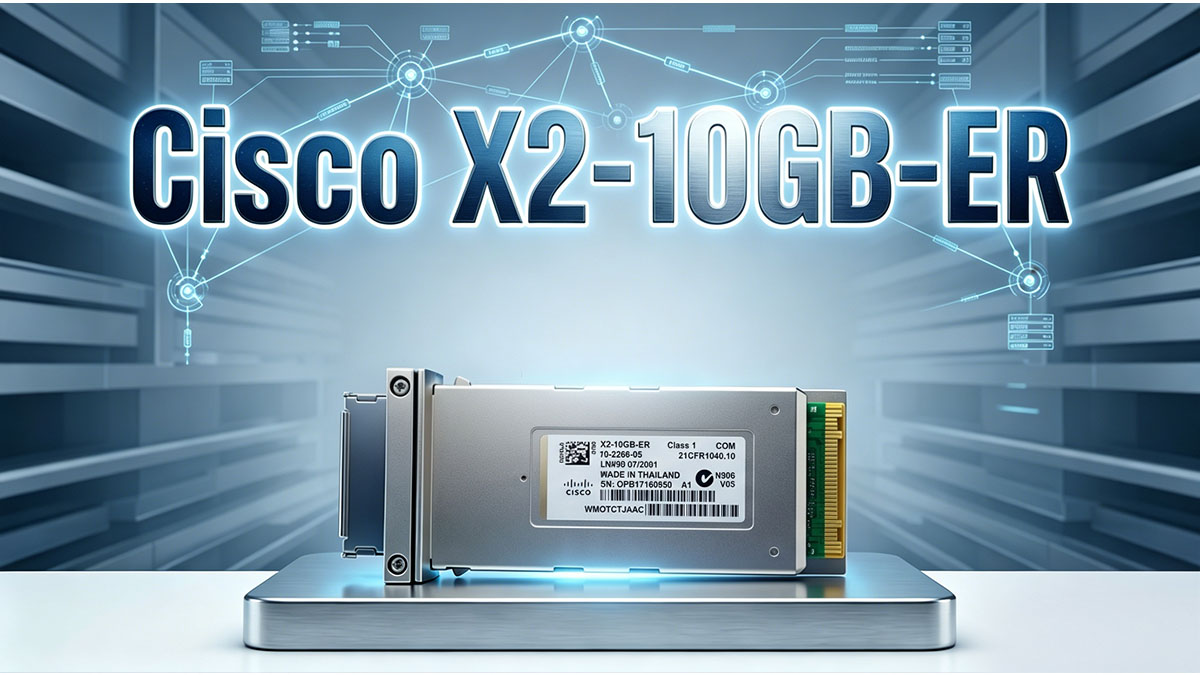
Modern enterprise networks, metro Ethernet infrastructures, and data center interconnections increasingly rely on high-speed 10Gbps fiber links to handle massive amounts of data. Cisco X2-10GB-ER optical transceivers, designed for extended reach single-mode fiber deployments, play a critical role in enabling reliable long-distance connections. Ensuring stable performance over distances up to 40km requires careful consideration of optical signal quality, as even small losses along the fiber path can significantly impact network reliability.
One of the most important factors influencing the performance of Cisco X2-10GB-ER modules is path loss, which encompasses signal attenuation due to fiber length, connector losses, splices, and environmental conditions. Understanding how to evaluate and manage path loss is essential for network engineers to maintain link integrity, optimize optical budgets, and prevent transmission errors. Without proper attention to these factors, long-haul 10Gbps links can experience degradation, affecting both speed and stability across enterprise and carrier networks.
This article provides a comprehensive guide to analyzing and optimizing path loss for Cisco X2-10GB-ER deployments. Readers will gain insights into:
- Core optical specifications and transmitter/receiver characteristics of X2-10GB-ER modules
- Key sources of path loss and methods to calculate optical budgets for long-distance links
- Practical best practices to minimize attenuation and maintain high network reliability
Through these points, the guide aims to equip network professionals with actionable knowledge to design, monitor, and maintain stable 10Gbps long-reach fiber connections.
🔩 Understanding Cisco X2-10GB-ER Optical Specifications
Cisco X2-10GB-ER modules are engineered to deliver reliable 10Gbps transmission over long-distance single-mode fiber, making them suitable for core networks, campus backbones, and metro Ethernet infrastructures. Understanding their technical characteristics, optical power range, and supported networking environments is essential for proper deployment and path loss management.
Core Technical Characteristics
The Cisco X2-10GB-ER module supports extended-reach single-mode fiber links, optimized for distances up to 40km. Its design ensures stable 10Gbps transmission at the 1550nm wavelength, which is less susceptible to chromatic dispersion over long distances. Key features include:
- 10Gbps Ethernet transmission standard for high-speed connectivity
- 1550nm wavelength operation for long-reach single-mode fiber
- Extended reach up to 40km over standard OS1/OS2 fibers
- X2 form factor compatible with legacy Cisco switches and routers
- Low power consumption suitable for dense optical environments
This combination of specifications makes X2-10GB-ER modules a dependable choice for long-haul enterprise and ISP applications.
Optical Power and Receiver Sensitivity
Maintaining proper optical power levels is critical to prevent signal degradation due to path loss. Cisco X2-10GB-ER modules provide defined transmit power ranges and receiver sensitivity levels, ensuring that the optical link remains within specification even over extended distances. The key points include:
- Typical transmit power: 0 to +4 dBm
- Receiver sensitivity: maximum -18 dBm
- Supports a sufficient optical margin to compensate for fiber attenuation, connector loss, and splices
- Provides stable operation within the recommended optical power budget to prevent bit errors
By monitoring these parameters, network engineers can ensure the signal remains strong enough for reliable 10Gbps communication without exceeding receiver limits.
Supported Networking Environments
The versatility of Cisco X2-10GB-ER modules allows deployment across multiple networking scenarios where long-distance optical connectivity is required. Its compatibility extends to various enterprise, ISP, and data center environments, including:
- Enterprise core networks connecting central routers and aggregation switches
- Metro Ethernet infrastructure linking multiple urban locations
- Campus backbone connectivity across buildings and sites
- Data center interconnect applications for high-speed server-to-server communication
- Telecommunications aggregation networks supporting long-haul traffic
These environments benefit from the module’s combination of long-distance reach, stable optical performance, and proven compatibility with existing Cisco hardware. Understanding these deployment contexts helps anticipate path loss challenges and plan for adequate optical budgets.
🔩 What Path Loss Means in Fiber Optic Networks
Path loss is a critical factor in fiber optic networks, directly affecting signal strength, data integrity, and long-distance 10Gbps link reliability. Understanding its sources, impact on optical budgets, and how it accumulates across the network is essential for Cisco X2-10GB-ER deployments. Proper path loss management ensures stable transmission over single-mode fibers and reduces the risk of unexpected service degradation.
Definition of Optical Path Loss
Optical path loss refers to the reduction of signal power as light travels through a fiber optic link. In long-distance 10Gbps networks, even small losses can degrade performance. Key aspects include:
- Signal attenuation occurs due to absorption and scattering in the fiber
- Insertion loss represents the loss introduced by connectors, splices, or other passive components
- Total path loss is the cumulative effect of all attenuation along the link
- Maintaining an adequate optical margin is critical to ensure the receiver can accurately detect the transmitted signal
Recognizing the difference between insertion loss and total path loss helps network engineers design optical links that remain within the transceiver’s operating range.
Major Sources of Path Loss
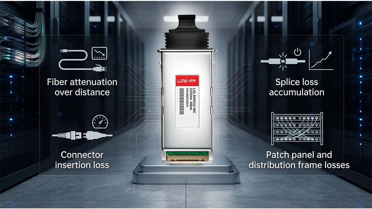
Path loss can arise from multiple points along a fiber optic link. Identifying and mitigating these sources is essential for maintaining network performance. Common contributors include:
- Fiber attenuation: Loss per kilometer due to fiber material characteristics, typically 0.25 dB/km at 1550nm for single-mode fiber
- Connector loss: Each connector introduces minor signal loss, often 0.2–0.5 dB per connection
- Splice loss: Mechanical or fusion splices contribute incremental attenuation, averaging 0.1–0.3 dB per splice
- Patch panels and distribution frames: Each additional passive interface adds to cumulative path loss
- Environmental degradation: Aging fibers, contamination, or bending can further increase loss
By accounting for these factors, engineers can calculate an accurate optical budget and ensure reliable transmission.
Path Loss vs Optical Power Budget
Path loss directly impacts the optical power budget, which defines the allowable loss a link can tolerate while maintaining signal integrity. For Cisco X2-10GB-ER modules, understanding this relationship is crucial:
- Optical power budget = Transmit power − Receiver sensitivity
- Total path loss must remain below the optical power budget to prevent errors
- Maintaining a safety margin (typically 2–3 dB) compensates for aging fibers or unexpected attenuation
- Exceeding path loss limits results in increased bit error rates and potential link failure
Monitoring and planning for optical power budgets ensures long-haul 10Gbps links remain stable even under changing environmental conditions or network upgrades.
🔩 Calculating Path Loss for Cisco X2-10GB-ER Deployments
Accurately calculating path loss is essential to ensure Cisco X2-10GB-ER links remain within their optical budget and can reliably support 10Gbps transmission over long distances. In practice, engineers evaluate every attenuation source across the fiber link and compare the total loss against the transceiver’s power budget to confirm stable operation.
Standard Optical Budget Calculation Method
A reliable optical link begins with a straightforward budget calculation that determines whether the system can tolerate total attenuation. The general principle is to subtract all expected losses from the available optical power range.
Before listing the calculation steps, it is important to understand that this method is used as the baseline for all long-reach fiber designs and is especially critical for 40km-class links.
- Start with transmit power (Tx) of the Cisco X2-10GB-ER module
- Subtract receiver sensitivity (Rx) to determine total optical budget
- Estimate total link loss including fiber, connectors, and splices
- Add a safety margin (typically 2–3dB) to account for aging and environmental variation
- Verify that total loss remains below available optical budget
After applying these steps, the remaining margin indicates whether the link is robust enough for long-term operation or requires design adjustments such as reducing connectors or improving fiber quality.
Fiber Attenuation Over 40km Links
Fiber attenuation is the dominant factor in long-distance deployments, especially for 40km single-mode links used by X2-10GB-ER modules. The attenuation level depends on fiber type, wavelength, and installation quality.
Before summarizing typical values, it is important to note that 1550nm operation significantly reduces attenuation compared to shorter wavelengths, making it suitable for extended reach applications.
| Fiber Type |
Attenuation at 1550nm |
Typical Use Case |
| OS1 |
~0.30 dB/km |
Indoor or legacy infrastructure |
| OS2 |
~0.25 dB/km |
Modern long-haul deployments |
| Low-loss OS2 |
~0.22 dB/km |
Optimized metro or ISP backbones |
These values show that over a 40km span, fiber loss alone can range from approximately 8.8dB to 12dB depending on fiber quality. This makes fiber selection a decisive factor in ensuring the Cisco X2-10GB-ER operates within safe optical limits.
Connector and Splice Loss Estimation
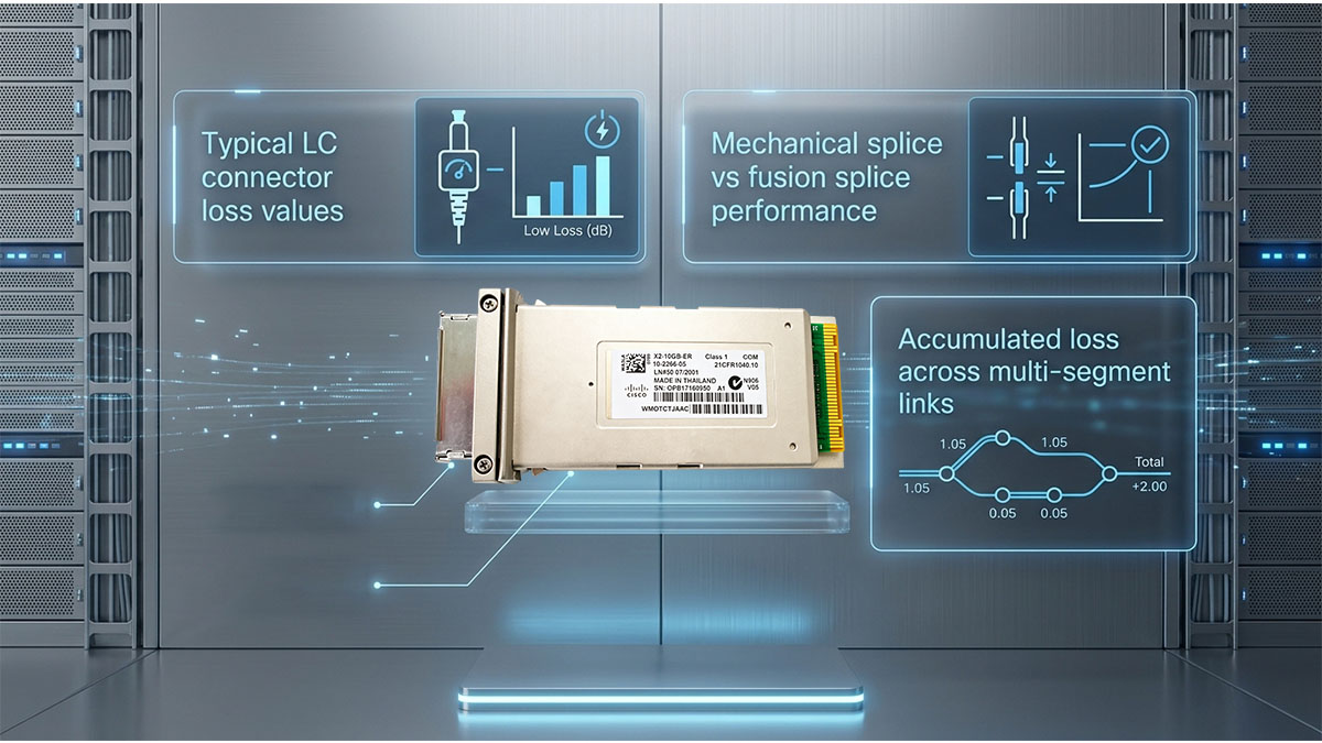
In addition to fiber attenuation, connectors and splices introduce incremental losses that accumulate along the optical path. Even small losses become significant in long-distance links.
Before listing typical values, it is important to emphasize that minimizing connection points is one of the most effective ways to reduce total path loss.
- LC connector pairs typically introduce 0.2–0.5dB loss per connection
- Fusion splices generally add 0.1–0.3dB loss per splice
- Mechanical splices may introduce slightly higher loss than fusion methods
- Patch panels can add cumulative loss when multiple cross-connects are used
- Each additional interface increases overall link attenuation
When designing Cisco X2-10GB-ER deployments, reducing unnecessary patching points is often more effective than upgrading fiber, especially in existing infrastructure.
Real-World Path Loss Calculation Example
A practical example helps illustrate how all loss components combine in a 40km Cisco X2-10GB-ER deployment scenario. This approach is commonly used during network design validation.
Before breaking down the values, it is important to note that real-world networks rarely operate at theoretical maximum efficiency due to infrastructure variability.
- Fiber loss (40km OS2 at 0.25dB/km): 10dB
- Connector pairs (4 connections at 0.3dB each): 1.2dB
- Splices (6 splices at 0.2dB each): 1.2dB
- Total estimated path loss: 12.4dB
- Typical optical budget availability: ~14–16dB range
After calculating the total loss, the remaining margin is approximately 1.6–3.6dB depending on transceiver variation. This margin is critical for absorbing environmental changes, aging fiber effects, and minor installation imperfections, ensuring stable long-term operation of the 10Gbps link.
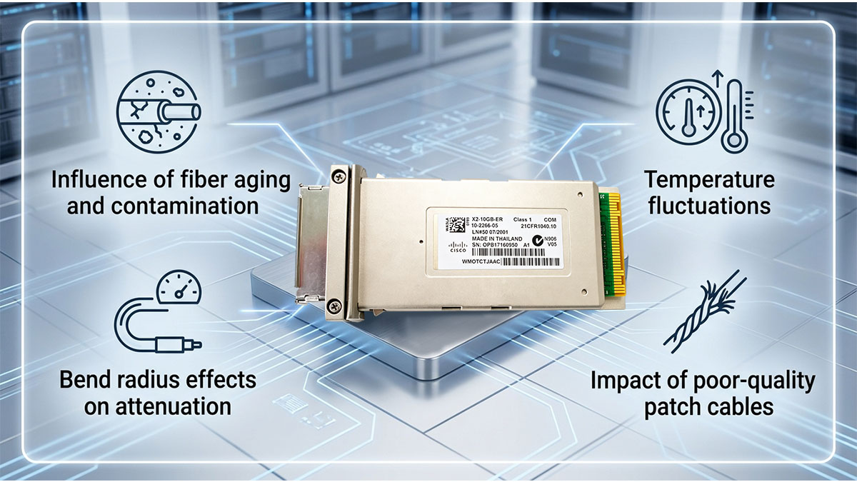
🔩 Factors That Influence Cisco X2-10GB-ER Path Loss Performance
The performance of Cisco X2-10GB-ER links is not determined by the transceiver alone, but by the entire optical channel from end to end. In real deployments, path loss varies significantly depending on fiber quality, environmental conditions, hardware compatibility, and signal integrity factors. Understanding these influences is essential for maintaining stable 10Gbps long-reach transmission.
Fiber Quality and Cable Type
Fiber infrastructure quality is one of the most important determinants of total path loss in Cisco X2-10GB-ER deployments. Even small differences in fiber grade or installation condition can significantly change attenuation over long distances.
Before listing key factors, it is important to note that 40km links amplify even minor imperfections in fiber infrastructure.
- OS2 single-mode fiber generally provides lower attenuation than OS1
- Older fiber installations may exhibit higher-than-rated loss due to aging or stress
- Micro-bending and macro-bending increase attenuation and reduce signal quality
- Contaminated or low-quality patch cables introduce additional insertion loss
- Improper cable routing can gradually degrade long-term optical performance
After considering these points, it becomes clear that fiber quality is not only a design parameter but also a long-term maintenance factor affecting link stability.
Environmental Conditions
Environmental factors can subtly but continuously increase path loss in real-world deployments. While fiber itself is passive, its physical surroundings directly affect signal integrity over time.
Before listing environmental influences, it is important to highlight that long-distance outdoor or campus deployments are particularly sensitive to these variations.
- Temperature fluctuations can slightly alter fiber refractive properties
- High humidity environments increase risk of connector contamination
- Dust and airborne particles degrade optical interfaces over time
- Outdoor enclosures may experience mechanical stress from expansion or vibration
- Water ingress in poorly sealed joints can significantly increase attenuation
These conditions often do not cause immediate failure but gradually reduce optical margin, making proactive monitoring essential for Cisco X2-10GB-ER links.
Network Hardware Compatibility
Hardware compatibility across optical components plays a key role in determining overall path loss performance. Even when fiber quality is high, mismatched or inconsistent equipment can introduce unexpected attenuation.
Before listing key hardware-related issues, it is important to understand that optical systems depend on precise alignment between transceivers, patch cords, and switching equipment.
- Inconsistent transceiver quality may result in varying transmit power levels
- Poor-quality or non-standard patch cables increase connector loss
- Legacy Cisco platforms may have different optical calibration tolerances
- Mixed-vendor environments can introduce slight interface mismatches
- Dirty or misaligned ports amplify insertion loss across connections
Ensuring compatibility across all optical components helps maintain predictable path loss behavior and stable 10Gbps performance.
Dispersion and Signal Integrity
Beyond physical attenuation, signal integrity issues such as dispersion and reflection also influence effective path loss in high-speed optical links. These effects become more noticeable over long distances like those supported by Cisco X2-10GB-ER.
Before listing key factors, it is important to recognize that dispersion does not always appear as direct power loss but still impacts usable signal quality.
- Chromatic dispersion spreads optical pulses over long distances at 1550nm
- Signal broadening increases bit error rate (BER) even if power levels are sufficient
- Reflective losses at connectors can distort signal waveform integrity
- Return loss from imperfect connections reduces effective signal clarity
- Accumulated dispersion effects become more pronounced near 40km limits
Together, these factors influence not only path loss measurements but also overall link reliability, making signal integrity management a critical part of long-distance 10Gbps network design.
🔩 Common Path Loss Challenges in 10G ER Networks
Path loss issues in 10G ER networks using Cisco X2-10GB-ER modules typically arise from a combination of attenuation buildup, physical contamination, and design miscalculations. In real deployments, these challenges often appear gradually as optical margin decreases, eventually leading to unstable links or intermittent packet errors if not addressed early.
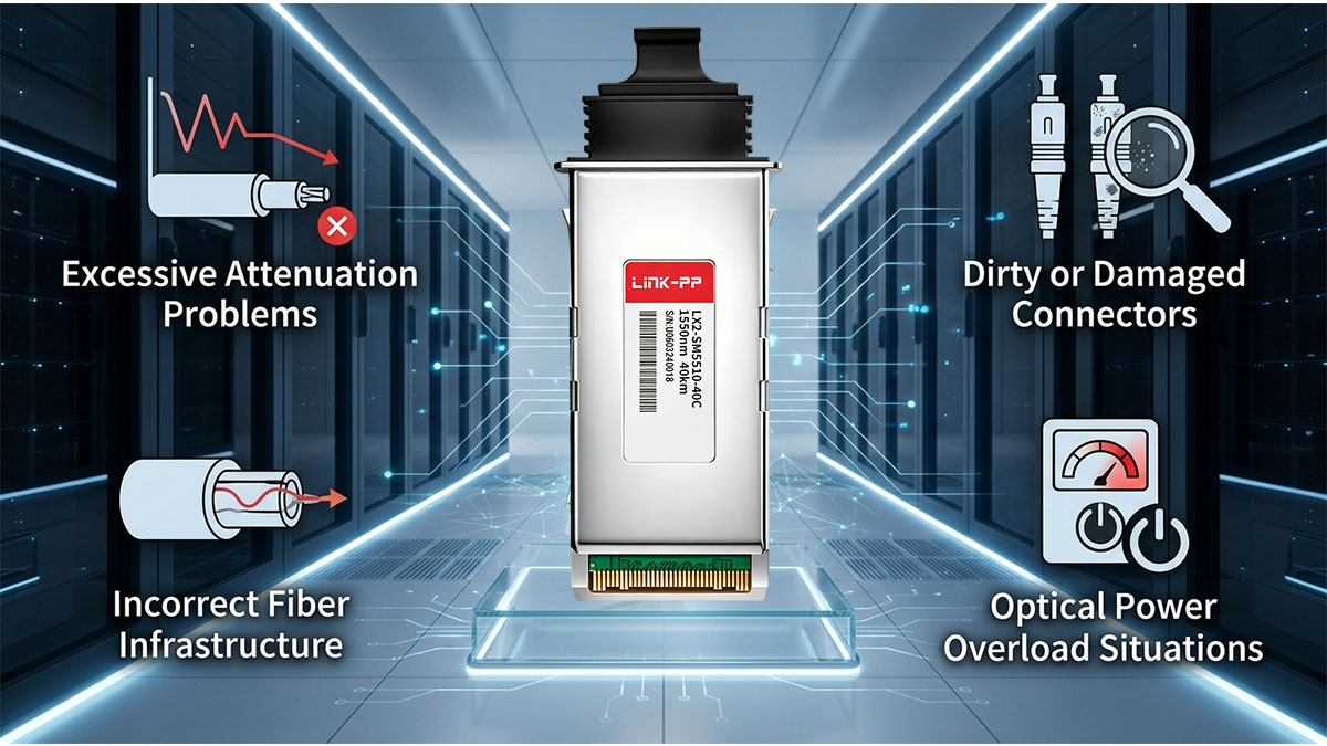
Excessive Attenuation Problems
Excessive attenuation is one of the most common causes of degraded performance in long-reach 10Gbps fiber links. It occurs when total path loss exceeds the optical budget of the Cisco X2-10GB-ER module.
Before listing typical causes, it is important to note that excessive attenuation is often the result of multiple small losses rather than a single failure point.
- Overestimated fiber distance without accurate loss calculation
- Too many connector points in the optical path
- High-loss patch panels or aging distribution frames
- Fiber bends exceeding recommended minimum radius
- Accumulated splice losses across multiple segments
When these factors combine, the remaining optical margin becomes too small, leading to unstable synchronization or increased bit error rates in 10Gbps traffic.
Dirty or Damaged Connectors
Connector contamination is a frequent and often underestimated contributor to path loss in Cisco X2-10GB-ER deployments. Even microscopic dust particles can significantly disrupt optical transmission.
Before listing key issues, it is important to emphasize that connector-related loss can appear suddenly and is highly sensitive to handling practices.
- Dust or oil contamination on LC connector end faces
- Scratches or pits on polished fiber surfaces
- Improper cleaning procedures before installation
- Repeated reconnections increasing wear and misalignment
- Dust caps not used or removed during handling
These issues increase insertion loss and reflection, reducing effective signal power and degrading overall link quality even when the fiber itself is in good condition.
Incorrect Fiber Infrastructure
Incorrect or mismatched fiber infrastructure design can introduce avoidable path loss that limits Cisco X2-10GB-ER performance. These issues are typically related to deployment planning or legacy cabling reuse.
Before listing common infrastructure mistakes, it is important to understand that fiber compatibility must be consistent across the entire link.
- Mixing single-mode and multimode fiber types in the same link
- Using incompatible connector standards or adapters
- Reusing legacy cabling without verifying attenuation levels
- Improperly labeled or undocumented fiber routes
- Poorly designed patching architecture with unnecessary hops
Such infrastructure issues often lead to unpredictable attenuation behavior and make troubleshooting significantly more difficult in operational networks.
Optical Power Overload Situations
While most discussions focus on excessive loss, overly short links can also create performance issues due to optical power overload at the receiver side of Cisco X2-10GB-ER modules.
Before listing key scenarios, it is important to note that ER-class optics are designed for long-distance transmission and may require attenuation in short links.
- Short fiber runs within campus or data center environments
- Direct connections without sufficient link distance
- High transmit power combined with low-loss fiber paths
- Lack of inline optical attenuators in short-reach deployments
- Receiver saturation causing signal distortion and errors
In these cases, optical attenuators are often required to bring received power within the acceptable range, ensuring stable 10Gbps operation without signal distortion.
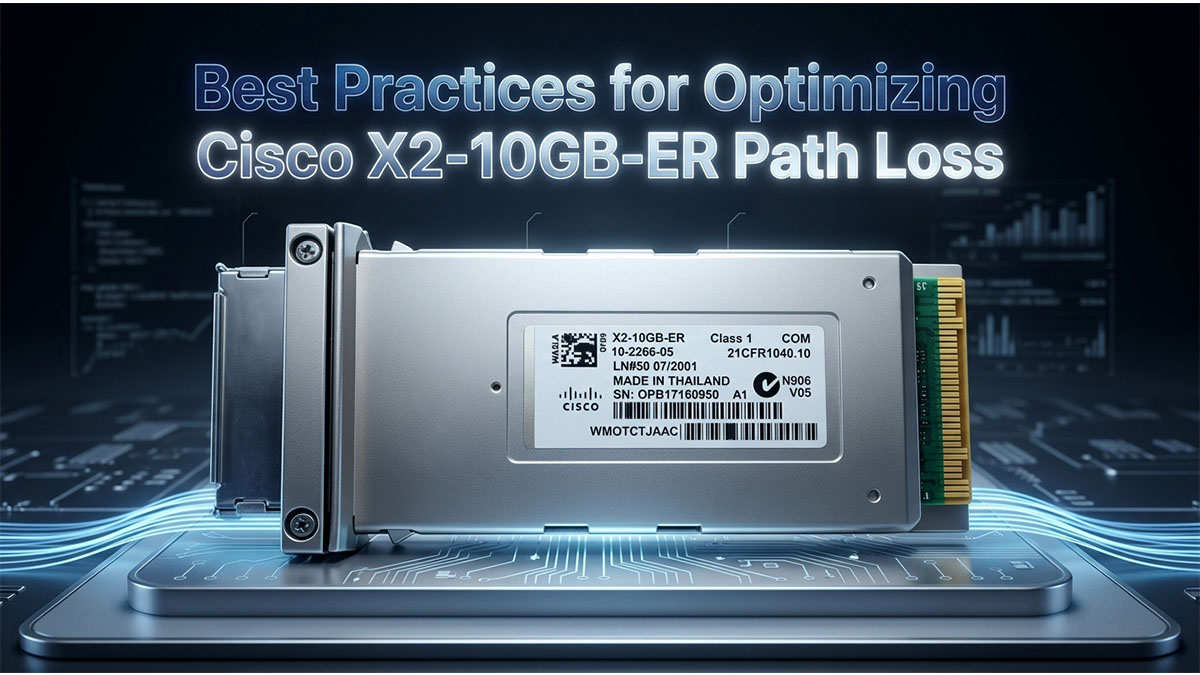
🔩 Best Practices for Optimizing Cisco X2-10GB-ER Path Loss
Optimizing path loss in Cisco X2-10GB-ER deployments is essential for maintaining stable 10Gbps long-distance connectivity and ensuring sufficient optical margin over time. In practice, optimization focuses on reducing unnecessary attenuation sources, improving fiber quality, and continuously monitoring optical performance across the entire link.
Designing an Efficient Optical Link
A well-designed optical link is the most effective way to control path loss before it becomes a performance issue. Proper design ensures that the Cisco X2-10GB-ER operates well within its optical budget even over 40km distances.
Before listing key design practices, it is important to emphasize that minimizing complexity in the optical path directly reduces cumulative loss.
- Reduce the number of intermediate patch panels and cross-connect points
- Plan direct fiber routes between core connection endpoints whenever possible
- Select low-loss OS2 single-mode fiber for long-haul deployments
- Limit the number of splices by using continuous fiber runs where feasible
- Design with an additional optical margin buffer beyond minimum requirements
After applying these practices, the overall link becomes more resilient to aging, environmental changes, and infrastructure expansion.
Maintaining Fiber Cleanliness
Fiber cleanliness is one of the most critical and often overlooked factors affecting path loss. Even small contamination at connector interfaces can significantly degrade optical performance in 10Gbps systems.
Before listing best practices, it is important to note that cleanliness issues often cause inconsistent and difficult-to-diagnose link degradation.
- Inspect all fiber end faces before installation using proper inspection tools
- Clean LC connectors using approved dry or wet cleaning methods
- Always use protective dust caps when fiber is not connected
- Avoid touching fiber end faces during handling and installation
- Establish routine cleaning schedules for high-density fiber environments
Consistent cleaning practices help maintain stable insertion loss levels and prevent gradual degradation of optical signal quality.
Monitoring Optical Performance
Continuous monitoring is essential for detecting early signs of increasing path loss in Cisco X2-10GB-ER links. Without monitoring, small degradations may go unnoticed until they impact network performance.
Before listing key monitoring approaches, it is important to highlight that modern transceivers often provide built-in diagnostics for real-time visibility.
- Use Digital Optical Monitoring (DOM) to track transmit and receive power levels
- Monitor optical margin trends over time instead of single-point readings
- Set threshold alarms for low receive power conditions
- Identify gradual signal degradation before link failure occurs
- Correlate optical performance with error rates and network logs
These monitoring practices allow proactive maintenance, reducing the risk of unexpected service disruption in long-distance 10Gbps networks.
Performing Accurate Optical Testing
Accurate testing ensures that calculated path loss values match real-world performance. This step is critical during installation, troubleshooting, and periodic network audits.
Before listing testing methods, it is important to note that multiple measurement techniques are often used together for validation.
- Use optical power meters to measure end-to-end signal strength
- Perform OTDR testing to identify loss points along the fiber route
- Validate connector and splice losses individually during commissioning
- Compare measured attenuation against calculated optical budget values
- Re-test links after infrastructure changes or maintenance activities
By combining these testing methods, engineers can precisely identify loss sources and ensure the Cisco X2-10GB-ER link remains within safe operating limits across its full 40km range.
🔩 Cisco X2-10GB-ER vs Other Long-Reach 10G Optics
Comparing Cisco X2-10GB-ER with other long-reach 10G optical modules helps clarify where it fits in modern network architectures and how path loss behavior differs across optical solutions. In practice, the key differences come from transmission distance, optical power budget, and deployment complexity rather than raw data rate, since all options operate at 10Gbps Ethernet.
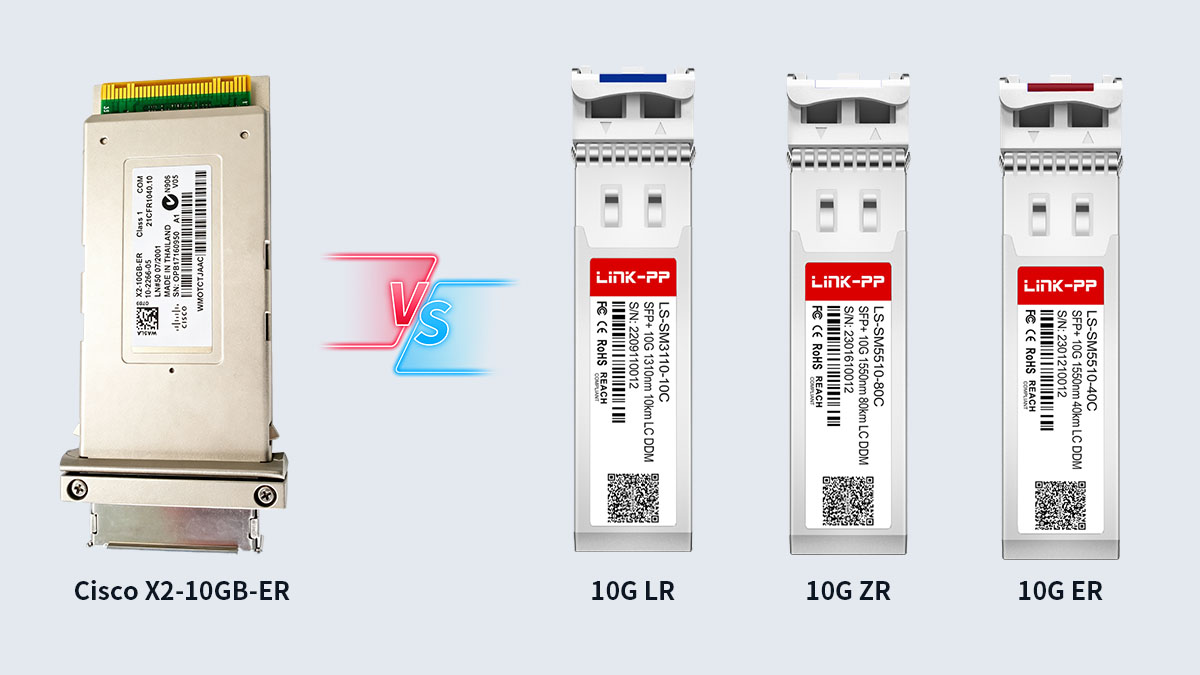
Comparison with 10G LR Modules
10G LR optics are commonly used for shorter single-mode fiber links, and their path loss tolerance is significantly lower than ER-class modules like Cisco X2-10GB-ER. This makes them more suitable for intra-campus or short metro connections.
Before presenting the comparison, it is important to highlight that LR and ER modules are optimized for different optical budgets and distance ranges.
| Feature |
10G LR |
Cisco X2-10GB-ER |
| Typical Reach |
Up to 10km |
Up to 40km |
| Wavelength |
1310nm |
1550nm |
| Optical Budget |
Lower |
Higher |
| Path Loss Tolerance |
Limited |
Extended |
These differences show that ER modules provide significantly greater tolerance to fiber attenuation, making them more suitable for long-distance links where path loss accumulation is unavoidable.
Comparison with 10G ZR Optics
10G ZR optics extend transmission distance even further than ER modules, but they also require stricter optical design considerations due to higher sensitivity to dispersion and link conditions.
Before listing key differences, it is important to note that ZR-class optics are typically used in metro and regional backbone networks.
- 10G ZR supports distances up to approximately 80km
- Cisco X2-10GB-ER is optimized for up to 40km links
- ZR modules require tighter control of dispersion and link engineering
- ER modules generally offer simpler deployment requirements
- ZR systems often demand more precise optical budget planning
While ZR provides greater reach, ER often offers a more balanced approach between distance, complexity, and path loss tolerance in typical enterprise and metro deployments.
Legacy X2 vs Modern SFP+ ER Modules
Cisco X2-10GB-ER belongs to an earlier generation of 10G optics, while SFP+ ER modules represent a more modern, compact evolution with improved port density and efficiency.
Before comparing them, it is important to understand that both support similar transmission principles but differ in form factor and system integration.
- X2 modules use a larger legacy form factor designed for older Cisco platforms
- SFP+ ER modules provide higher port density in modern switches
- Power consumption is generally higher in X2-based designs
- SFP+ ecosystems offer broader interoperability across vendors
- Migration to SFP+ is often part of long-term network modernization strategies
Despite these differences, both solutions must still manage path loss carefully to maintain reliable 10Gbps transmission over long distances.
🔩 Deployment Scenarios Where Path Loss Analysis Is Critical
Path loss analysis becomes especially important in Cisco X2-10GB-ER deployments where fiber spans are long, infrastructure is distributed, and optical margins must remain stable over time. In these scenarios, even small miscalculations in attenuation can lead to degraded 10Gbps performance or intermittent link instability. Proper evaluation ensures that optical budgets are maintained across real-world network environments.
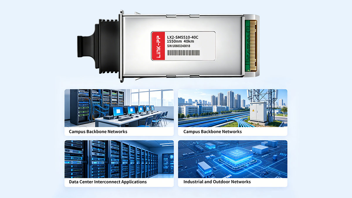
Campus Backbone Networks
Campus backbone networks often connect multiple buildings over distances that can approach or exceed several kilometers, making path loss a key design consideration. Cisco X2-10GB-ER is frequently used in these environments when extended reach is required.
Before listing typical deployment characteristics, it is important to note that campus environments often combine both controlled indoor and variable outdoor fiber paths.
- Inter-building connections across large enterprise or university campuses
- Mixed indoor/outdoor fiber routes with varying environmental exposure
- Multiple patch panels and distribution points increasing cumulative loss
- Medium-distance links where optical margin must remain stable under growth
- Expansion-prone infrastructure requiring future-proof optical budgeting
These factors make path loss planning essential to ensure consistent 10Gbps performance as campus networks evolve.
Metro Ethernet Infrastructure
Metro Ethernet environments represent one of the most demanding use cases for Cisco X2-10GB-ER, as they involve long-distance fiber links across urban areas with complex routing and shared infrastructure.
Before listing key characteristics, it is important to emphasize that metro networks often experience higher variability in fiber quality and route design.
- Long-distance connections between central offices and aggregation sites
- Shared metropolitan fiber infrastructure with multiple handoff points
- High reliance on accurate optical budget planning for service reliability
- Increased risk of connector and splice accumulation along routes
- Strict service-level requirements for uptime and latency stability
Because of these conditions, precise path loss analysis is critical to ensure stable service delivery in metro-scale 10Gbps networks.
Data Center Interconnect Applications
Data center interconnect (DCI) scenarios rely on high-performance optical links to connect geographically separated facilities, where even minor path loss variations can impact synchronization and traffic flow.
Before listing key considerations, it is important to highlight that DCI links often prioritize both performance stability and deterministic latency.
- High-capacity links between geographically distributed data centers
- Dedicated fiber paths designed for low-latency communication
- Strict optical margin control to support continuous data replication
- Sensitivity to dispersion and accumulated attenuation over distance
- Need for predictable performance under peak traffic loads
In these environments, Cisco X2-10GB-ER provides reliable long-reach connectivity, but only when path loss is carefully managed.
Industrial and Outdoor Networks
Industrial and outdoor deployments introduce additional environmental and physical challenges that can significantly affect optical attenuation and path loss behavior.
Before listing key issues, it is important to note that these environments often combine long distances with harsh operating conditions.
- Outdoor surveillance networks spanning large geographic areas
- Utility and transportation infrastructure monitoring systems
- Exposure to temperature extremes, moisture, and vibration
- Increased risk of fiber bending or physical stress on cabling
- Remote locations where maintenance and troubleshooting are limited
Due to these conditions, path loss analysis becomes essential not only during design but also throughout the operational lifecycle to ensure long-term link reliability.
🔩 Conclusion
Cisco X2-10GB-ER path loss management is a fundamental requirement for ensuring stable, long-distance 10Gbps optical performance, especially in 40km single-mode fiber deployments. Proper understanding of optical budget, attenuation sources, and real-world link conditions allows network engineers to design reliable infrastructures that fully leverage the capabilities of the Cisco X2-10GB-ER module while maintaining consistent signal integrity across enterprise, metro, and data center environments.
Before summarizing the key takeaways, it is important to emphasize that path loss control is not a one-time task but an ongoing design and maintenance consideration throughout the lifecycle of the optical network.
- Cisco X2-10GB-ER supports extended-reach 10Gbps transmission up to 40km over single-mode fiber with 1550nm wavelength operation
- Path loss is primarily driven by fiber attenuation, connector insertion loss, splice accumulation, and environmental conditions
- Accurate optical budget calculation is essential to ensure total attenuation remains within safe receiver sensitivity limits
- Monitoring tools such as DOM and optical power meters help maintain long-term link stability
- Proper fiber design, cleanliness, and infrastructure planning significantly reduce unnecessary loss and improve reliability
These core principles highlight that stable long-reach 10G performance depends on both correct initial engineering and continuous operational monitoring.
To further improve network reliability and optimize optical connectivity performance, it is important to choose high-quality optical components and ensure compatibility across the entire transmission chain. For organizations planning upgrades, expansions, or long-distance fiber deployments, exploring reliable optical solutions and transceiver options from the LINK-PP Official Store can help support consistent network performance and long-term infrastructure stability.


