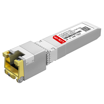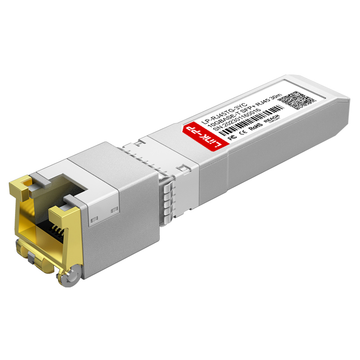
In modern enterprise and homelab network architectures, integrating twisted-pair copper infrastructure with high-density optical switch ports is a frequent operational requirement. The QSFPTEK QT-SFP-10G-T transceiver serves as a physical-layer converter designed to bridge this gap, mapping the 10GBASE-T standard (IEEE 802.3an) to the high-speed SFI electrical interface defined by the SFF-8431 multi-source agreement (MSA).
While optical SFP+ transceivers rely on low-power semiconductor lasers, copper 10GBASE-T modules require dedicated physical layer (PHY) silicon to perform complex digital signal processing (DSP). This processing is necessary to mitigate line attenuation, echo, and near-end crosstalk (NEXT) inherent to high-frequency signals running over twisted-pair copper cables. Consequently, implementing the QT-SFP-10G-T introduces specific electrical, thermal, and mechanical constraints—such as a 30-meter link limitation over Category 6A cabling and a typical power draw of 2.3W to 2.5W.
This technical analysis provides a systematic breakdown of the QSFPTEK QT-SFP-10G-T transceiver. It examines the 10GBASE-T physical layer specifications, maps the 20-pin host-side electrical interface, analyzes the signal definitions, and evaluates the operational variables—such as thermal dissipation and multi-gigabit negotiation—required for stable deployment.
🔷 What is the QSFPTEK QT-SFP-10G-T Transceiver?
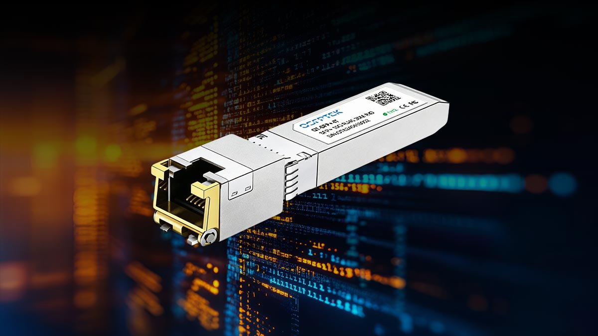
The QSFPTEK QT-SFP-10G-T is a hot-pluggable, copper-based Small Form-factor Pluggable Plus (SFP+) transceiver module designed to deliver 10 Gigabit Ethernet connectivity over RJ45 twisted-pair cabling. It serves as a physical-layer converter, allowing network operators to utilize copper patch cords within standard optical SFP+ cages.
+-------------------+      SFI Interface      +-------------------------+      RJ45 Interface      +-------------------+
|                   |  <===================>  |  QSFPTEK QT-SFP-10G-T   |  <====================>  |                   |
|  Host Switch Port |     (2-wire SerDes)     |                         |     (PAM16 Signals)      |   Target Device   |
|     (SFP+ Cage)   |                         |   [Integrated PHY IC]   |   (Cat6a/Cat7, max 30m)  |  (NIC, NAS, etc.) |
+-------------------+                         +-------------------------+                          +-------------------+
From a system architecture perspective, native SFP+ ports communicate using the SFI (SFP+ Serial Interface), which is a high-speed, low-voltage differential signaling specification defined in the SFF-8431 standard. Because copper media requires entirely different electrical modulation than optical fiber, the QT-SFP-10G-T incorporates an onboard, highly integrated Physical Layer (PHY) integrated circuit (IC).
The onboard PHY IC performs several critical operations:
-
Signal Conversion: It serializes and deserializes data, translating the host-side SFI high-speed differential signals into the PAM16 (Pulse Amplitude Modulation 16) line-coding format utilized by 10GBASE-T.
-
Digital Signal Processing (DSP): The PHY chip runs continuous echo cancellation, digital equalization, and near-end/far-end crosstalk mitigation. This processing is mandatory to preserve signal integrity across the high-frequency spectrum required by 10 Gbps transmission over copper.
-
Media Adaptation: It routes these processed signals to a standard 8-pin physical RJ45 connector, making the module compatible with Category 6A (Cat6a) and Category 7 (Cat7) shielded or unshielded twisted-pair cables.
By encapsulating these complex PHY operations within the standard SFP+ form factor, the QT-SFP-10G-T enables seamless interoperability between optical-only switches and copper-only end nodes, such as Network Attached Storage (NAS) units, servers, and hardware firewalls.
🔷 QSFPTEK QT-SFP-10G-T 10GBASE-T Specification Overview
Integrating a copper transceiver into an optical SFP+ port requires strict compliance with mechanical, electrical, and thermal parameters defined by the Small Form Factor (SFF) Multi-Source Agreements (MSAs) and IEEE standards. The following specifications detail the operational boundaries and compliance metrics of the QSFPTEK QT-SFP-10G-T transceiver.
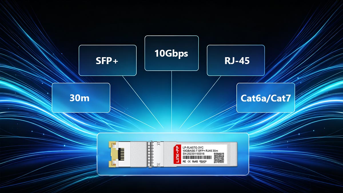
Technical 10Gbase-T Specification Table
| Parameter | Specification | Standard / Reference |
| Form Factor | SFP+ (Small Form-factor Pluggable Plus) | SFF-8432 (Mechanical Envelope) |
| Media Interface | RJ45 | IEC 60603-7 |
| Data Rate | 10 Gbps (Supports 5G, 2.5G, 1G, and 100M auto-negotiation) | IEEE 802.3an (10GBASE-T), IEEE 802.3bz |
| Max Reach (10G) | 30 meters over Category 6A / Category 7 | IEEE 802.3an |
| Supply Voltage | 3.3V Nominal (3.13V to 3.47V Range) | SFF-8431 |
| Max Operating Current | ~750 mA (Under full 10G load at 30m) | Host Power Budget limits |
| Power Dissipation | ≤ 2.5 Watts (Typical operating: 2.3W) | SFF-8431 Power Level II |
| DDM / DOM Support | Yes (Voltage, internal temperature monitoring) | SFF-8472 |
| Operating Temperature | 0°C to 70°C (32°F to 158°F) - Commercial Range | Case Temperature |
| Storage Temperature | -40°C to 85°C (-40°F to 185°F) | Ambient Temperature |
Electrical and Distance Tradeoffs
The 30-meter distance limitation of the QT-SFP-10G-T is a direct result of electrical and thermal constraints defined by the SFF-8431 host interface specification.
+-------------------------------------------------------------------------+
|                              Power & Distance Tradeoff                  |
|                                                                         |
|  Standard 10GBASE-T (Native RJ45 Switch Port):                          |
|  [Power: up to 5W per port] -------------------------------> [100m Cat6a]|
|                                                                         |
|  SFP+ Port Constraints (SFF-8431 Power Level II):                       |
|  [Power: max 2.5W per port] -------------> [30m Cat6a]                  |
+-------------------------------------------------------------------------+
In native 10GBASE-T switch ports (RJ45-to-RJ45), the system power supply is designed to deliver up to 4W to 5W per port, enabling the PHY to drive high-frequency electrical signals up to the standard limit of 100 meters over Category 6A cabling.
However, standard optical SFP+ cages are governed by SFF-8431, which classifies ports into:
-
Power Level I: Up to 1.0W
-
Power Level II: Up to 1.5W (expandable to 2.5W with host-side thermal management)
To avoid overloading the host switch's power supply rails and violating the Power Level II constraint, the integrated PHY in the QT-SFP-10G-T operates with reduced transmitter launch power. This lower transmit power limits the maximum loop reach to 30 meters, which successfully restricts the maximum power consumption to ≤ 2.5W while preserving error-free data transmission.
🔷 SFP+ 10GBASE-T Pinout Configuration, Signal Map, and Electrical Pad Layout
The electrical interface of the QSFPTEK QT-SFP-10G-T transceiver consists of a 20-pin card edge connector that mates directly with the host system's SFP+ receptacle. This physical connection, governed by the SFF-8431 specification, handles high-speed data transfer, low-speed control and status signals, power delivery, and ground references.
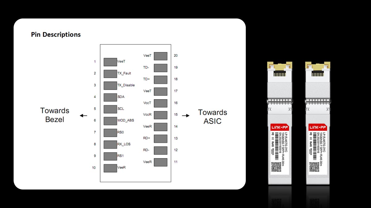
PCB Card Edge Pad Layout
The diagram below illustrates the physical arrangement of the 20 electrical pads on the printed circuit board (PCB) of the transceiver module. The layout is split into top and bottom card-edge interfaces to isolate high-speed differential pairs from interference.
TOP OF BOARD (Component Side)                    BOTTOM OF BOARD (Solder Side)
  +-------------------------------------+          +-------------------------------------+
  |                                     |          |                                     |
  |  [20] VeeT   [19] TD-    [18] TD+   |          |  [1]  VeeR   [2]  TX_Fault [3]  TX_Dis|
  |  [17] VeeT   [16] VccT   [15] VccR  |          |  [4]  SDA    [5]  SCL      [6]  Mod_ABS|
  |  [14] VeeR   [13] RD+    [12] RD-   |          |  [7]  RS0    [8]  RX_LOS   [9]  RS1   |
  |  [11] VeeR                          |          |  [10] VeeR                          |
  |                                     |          |                                     |
  +-------------------------------------+          +-------------------------------------+
Signal Map and Electrical Pin Definitions
The following table provides the exact signal mapping, logic states, and directional paths relative to the QT-SFP-10G-T transceiver module:
| Pin | Name | Direction | Signal Type | Description |
| 1 | VeeR | Reference | Ground | Receiver Ground (Common with Transmitter Ground). |
| 2 | TX_Fault | Output | Open-Collector | Transmitter Fault Indication. Active High. |
| 3 | TX_Disable | Input | LVTTL | Transmitter Disable. High disables transmitter; Low enables. |
| 4 | SDA | Bi-directional | LVTTL | 2-wire Serial Interface Data Line (I2C interface). |
| 5 | SCL | Input | LVTTL | 2-wire Serial Interface Clock Line (I2C clock). |
| 6 | Mod_ABS | Output | Hardwired | Module Absent. Connected to VeeT or VeeR inside module. |
| 7 | RS0 | Input | LVTTL | Rate Select 0. Typically not implemented or pulled low. |
| 8 | RX_LOS | Output | Open-Collector | Loss of Signal. High indicates lack of valid carrier signal. |
| 9 | RS1 | Input | LVTTL | Rate Select 1. Typically not implemented or pulled low. |
| 10 | VeeR | Reference | Ground | Receiver Ground (Common with Transmitter Ground). |
| 11 | VeeR | Reference | Ground | Receiver Ground (Common with Transmitter Ground). |
| 12 | RD- | Output | AC-Coupled | Inverted Receiver Data Output (Differential SFI Pair). |
| 13 | RD+ | Output | AC-Coupled | Non-Inverted Receiver Data Output (Differential SFI Pair). |
| 14 | VeeR | Reference | Ground | Receiver Ground (Common with Transmitter Ground). |
| 15 | VccR | Power | +3.3V | Receiver Power Supply (Typically decoupled on host). |
| 16 | VccT | Power | +3.3V | Transmitter Power Supply (Typically decoupled on host). |
| 17 | VeeT | Reference | Ground | Transmitter Ground (Common with Receiver Ground). |
| 18 | TD+ | Input | AC-Coupled | Non-Inverted Transmitter Data Input (Differential SFI Pair). |
| 19 | TD- | Input | AC-Coupled | Inverted Transmitter Data Input (Differential SFI Pair). |
| 20 | VeeT | Reference | Ground | Transmitter Ground (Common with Receiver Ground). |
Key Electrical Interface Groups
1. High-Speed Differential SFI Interface (TD+/-, RD+/-)
The transmit (TD+ / TD-) and receive (RD+ / RD-) lines handle the 10.3125 Gbps serial data streams. These lines utilize low-voltage differential signaling and require integrated AC coupling capacitors inside the QT-SFP-10G-T module. The nominal differential impedance of these traces is controlled at 100 Ohms.
2. Power Rails (VccT, VccR)
Pins 15 and 16 provide +3.3V power to the module's internal components. Because 10GBASE-T transceivers draw near-maximum current limits (up to 750mA), proper board layout on the host switch must include filter inductors and decoupling capacitors to minimize high-frequency noise and power supply ripple on these rails.
3. Module Detection and Control (Mod_ABS, TX_Disable)
-
Mod_ABS (Pin 6): Pulled low to ground inside the transceiver. When inserted, the host switch senses this connection to determine that a module is physically present.
-
TX_Disable (Pin 3): An internal pull-up resistor keeps this line high by default. The host switch must pull this pin low to enable the transceiver's onboard PHY to initiate link negotiation over the RJ45 port.
🔷 Hardware Compatibility, Multi-Gigabit Auto-Negotiation, and Cable Requirements
Deploying the QT-SFP-10G-T requires aligning the logical programming of the transceiver with the host switch operating system, and selecting physical cabling that meets electrical parameters.
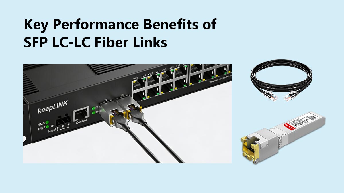
EEPROM Customization and Host Compatibility
Standard network switches often enforce vendor-locking mechanisms that reject third-party transceivers. To bypass these restrictions, the QT-SFP-10G-T relies on customized firmware written to its onboard EEPROM.
The host switch reads a 256-byte database via the 2-wire serial interface (I2C) at address A0h, as specified by the SFF-8472 standard. This database contains vendor-specific identifiers, including:
-
Vendor Name (Bytes 20–35)
-
Vendor OUI (Bytes 37–39)
-
Vendor Part Number (Bytes 40–55)
-
Security Checksum (Byte 63 and 95)
Host Switch Memory Map (SFF-8472)
  +---------------------------------------------+
  |  Address A0h (Identifier, Serial, Vendor ID) |  <--- Read during initialization
  +---------------------------------------------+
  |  Address A2h (Digital Diagnostics Monitor)  |  <--- Voltage, Temp, Bias current
  +---------------------------------------------+
QSFPTEK pre-programs these bytes with specific OEM signatures (such as Cisco, Ubiquiti, Mikrotik, or Juniper). This allows the transceiver to pass host-side initialization checks without requiring manual overrides like the Cisco CLI command service unsupported-transceiver.
Multi-Gigabit Auto-Negotiation and Rate Matching
A key advantage of copper-based SFP+ transceivers is their ability to auto-negotiate network speeds below 10 Gbps, compliant with the IEEE 802.3bz standard (2.5GBASE-T and 5GBASE-T).
+-------------------+      Fixed 10G Link      +----------------------+   Auto-Negotiation   +-------------------+
|                   |  <====================>  | QSFPTEK QT-SFP-10G-T |  <=================>  |                   |
| Host Switch Port  |   SFI Interface (10G)    |                      |   RJ45 Interface  | Client Device     |
| (10G Only SFP+)   |                          | [Internal PHY Buffer] |  (1G / 2.5G / 5G)  | (2.5G Port / NAS) |
+-------------------+                          +----------------------+                       +-------------------+
Because many older SFP+ host switch ports only support fixed 10G (10.3125 Gbps) or 1G (1.25 Gbps) electrical inputs, they cannot natively scale their serial interfaces down to 2.5G or 5G. The QT-SFP-10G-T overcomes this limitation using an internal rate-matching PHY:
-
Host-Side Link: The transceiver maintains a fixed 10 Gbps SFI link with the host switch port.
-
Line-Side Link: The internal PHY auto-negotiates the copper connection to 5 Gbps, 2.5 Gbps, or 1 Gbps with the client device (e.g., a Wi-Fi Access Point or standard workstation).
-
Flow Control: To prevent packet loss due to the speed discrepancy, the transceiver's onboard PHY chip utilizes internal FIFO buffers and manages packet delivery using IEEE 802.3x flow control (PAUSE frames) or MAC-layer rate adaptation.
Cabling Specifications and Distance Boundaries
To ensure reliable signal-to-noise ratios (SNR) and maintain Bit Error Rates (BER), the cabling infrastructure must match the designated transmission speeds:
| Cable Category | Shielding Type | Supported Data Rate | Maximum Reach | Recommended Application |
| Category 5e | UTP or STP | 1 Gbps / 2.5 Gbps | 100 meters | Legacy client connections |
| Category 6 | UTP | 5 Gbps | 100 meters | Standard building horizontal runs |
| Category 6 | UTP / STP | 10 Gbps | 37 to 55 meters | Short links (reach depends on crosstalk) |
| Category 6A | STP (F/UTP or S/FTP) | 10 Gbps | 30 meters | High-density rack connections |
| Category 7 | STP (S/FTP) | 10 Gbps | 30 meters | Datacenter and high-noise environments |
Note: While Category 6A is standard for 100-meter 10GBASE-T runs on native RJ45 switches, the 30-meter limit on the QT-SFP-10G-T must be respected to operate within the 2.5W SFP+ host port power allocation.
Shielding Considerations
Using Shielded Twisted Pair (STP) cabling is highly recommended in environments deploying multiple QT-SFP-10G-T modules. STP provides electromagnetic shielding that prevents Alien Crosstalk (ANEXT)—the high-frequency signal coupling between adjacent copper cables running in parallel cable trays, which can degrade 10G link performance.
🔷 Managing Power Consumption and Thermal Dispersal
10GBASE-T SFP+ copper transceivers run significantly warmer than their optical or direct-attach copper (DAC) counterparts. Understanding the thermodynamic limitations of the QT-SFP-10G-T and implementing proper heat-dissipation strategies is necessary to maintain network uptime.
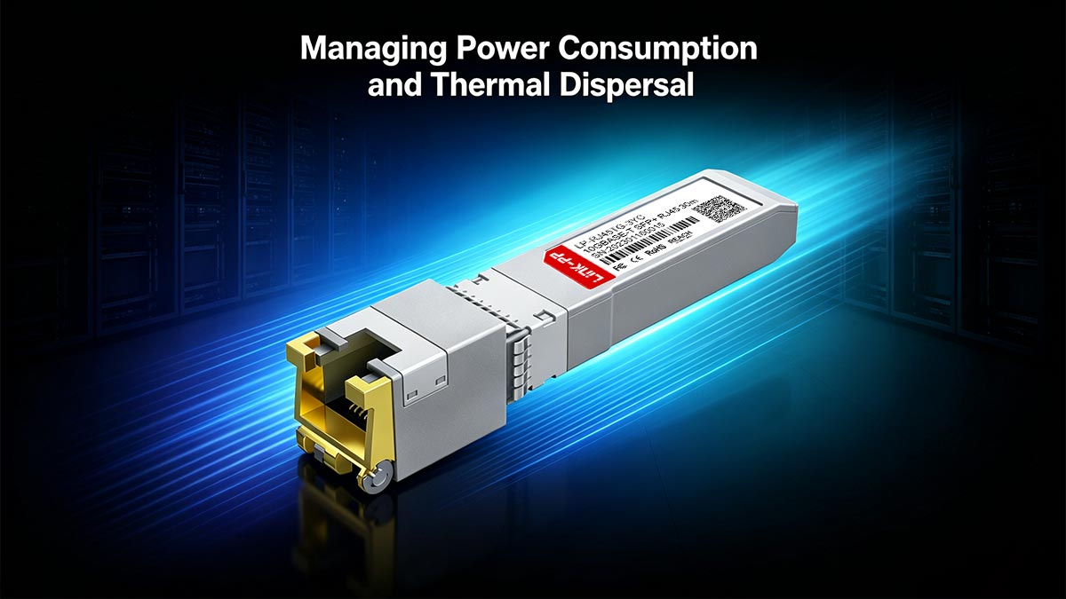
The Physics of 10GBASE-T Heat Generation
The high power draw of the QT-SFP-10G-T (up to 2.5 Watts) is driven by the internal PHY chip. Unlike fiber-optic transceivers, which use power primarily to drive a low-current laser diode (typically < 1.0W total), a 10GBASE-T module must continuously run high-frequency digital signal processors (DSP) and analog-to-digital converters (ADC) to maintain the link over twisted-pair copper.
+--------------------------------------------------------------------------+
|                       Comparative Power & Heat Output                    |
|                                                                          |
|  10G SFP+ SR Optical Transceiver:                                        |
|  [|||||||] ~1.0 Watt  --> Minimal heat dissipation                       |
|                                                                          |
|  10G SFP+ Direct Attach Copper (DAC):                                    |
|  [|] ~0.1 Watt        --> Passive, near-zero heat                        |
|                                                                          |
|  QSFPTEK QT-SFP-10G-T Copper Module:                                     |
|  [|||||||||||||||||||||||||] ~2.5 Watts --> High thermal density          |
+--------------------------------------------------------------------------+
This electrical work is released as thermal energy concentrated within the very small surface area of the SFP+ metal housing. If this heat is not dissipated, the internal junction temperature of the PHY chip can exceed its maximum operating limit (typically 90°C), leading to bit errors, link instability, or thermal shutdown.
Thermal Management and Deployment Best Practices
To prevent localized overheating when integrating the QT-SFP-10G-T into switches or routers, observe the following physical placement guidelines:
1. Port Interleaving (Spacing)
Avoid populating adjacent SFP+ ports with copper RJ45 transceivers. Instead, alternate copper modules with optical transceivers or DAC cables, which have lower thermal profiles. This structural spacing provides a heat sink pathway through the unpopulated or low-temperature ports.
POOR DESIGN (Concentrated Heat)         RECOMMENDED DESIGN (Interleaved)
     +---------------------------------+     +---------------------------------+
     | [RJ45] [RJ45] [RJ45] [RJ45] ... |     | [RJ45] [Fiber] [RJ45] [Fiber]   |
     | [RJ45] [RJ45] [RJ45] [RJ45] ... |     | [Fiber] [RJ45] [Fiber] [RJ45]   |
     +---------------------------------+     +---------------------------------+
2. Avoid Fanless Switches for Multi-Port Deployments
Fanless or passively cooled switches rely entirely on natural convection. While they are silent, they generally cannot dissipate the cumulative heat generated by multiple 2.5W SFP+ modules. Only deploy the QT-SFP-10G-T in active-airflow environments (front-to-back or back-to-front forced air cooling) if populating multiple ports.
3. Maintain Airflow Integrity
Keep rack spaces clear of obstructions and verify that the switch chassis fans are functioning correctly. High ambient rack temperatures (above 40°C) will rapidly elevate the module's case temperature past its commercial-grade 70°C limit.
SFF-8472 Digital Diagnostics (DDM) for Thermal Tracking
The QT-SFP-10G-T includes a micro-controller that supports Digital Diagnostics Monitoring (DDM) via the 2-wire serial bus at address A2h. Network administrators can query this data in real-time through the switch OS CLI (e.g., show interfaces transceiver detail) to monitor:
-
Module Temperature: Real-time case temperature.
-
Supply Voltage: Voltage level supplied by the host (nominal 3.3V).
Transceiver Monitoring Thresholds (Typical)
  +-------------------------------------------------------------------------+
  |  Normal Operation:  0°C to 64°C (Safe Zone)                             |
  |  High Warning:      65°C        (Inspect cooling and port spacing)     |
  |  High Alarm:        70°C        (Risk of packet drop or link failure)   |
  +-------------------------------------------------------------------------+
By configuring SNMP traps or automated syslog alerts based on these DDM thresholds, administrators can identify overheating modules before they cause network degradation.
🔷 When to Choose QT-SFP-10G-T vs. DAC or Fiber
Selecting the appropriate physical medium for 10G links requires balancing performance metrics such as transmission reach, electrical power constraints, latency, and capital expenditure. The table below compares the QSFPTEK QT-SFP-10G-T copper transceiver, Passive Direct Attach Copper (DAC) cables, and 10GBASE-SR Multimode Fiber optics.
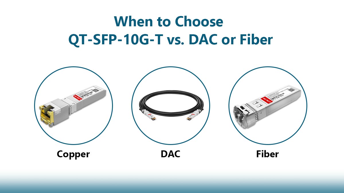
Comparison Matrix: Copper vs. DAC vs. Fiber
| Feature / Metric | QT-SFP-10G-T (10GBASE-T) | Passive SFP+ DAC | SFP+ Fiber (10GBASE-SR) |
| Physical Media | Twisted-pair Copper (Cat6a/7) | Twinaxial Copper | Multimode Fiber (OM3/OM4) |
| Connector Type | RJ45 | Hardwired SFP+ Shell | LC Duplex |
| Maximum Reach | Up to 30 meters | Up to 7 meters | Up to 300m (OM3) / 400m (OM4) |
| Typical Power | 2.3W to 2.5W | < 0.1W | 0.8W to 1.2W |
| Link Latency | ~2.0 to 2.5 microseconds | ~0.1 microseconds | ~0.1 microseconds |
| EMI Immunity | Moderate (Susceptible to noise) | High | Absolute (Immune to EMI) |
| Relative Cost | Medium (Saves cabling cost) | Lowest (All-in-one cable) | Higher (Requires transceiver + patch) |
Decision Framework and Deployment Scenarios
1. When to Deploy the QT-SFP-10G-T (10GBASE-T)
The 10GBASE-T SFP+ copper module is highly suited for hybrid integration scenarios where fiber or direct twinax cannot be deployed:
-
Existing RJ45 Infrastructure: When the facility is already wired with structured Category 6A or 7 copper cabling, and pulling new fiber optic cables is cost-prohibitive.
-
Copper-Only End Nodes: When connecting an optical switch port to servers, Network Attached Storage (NAS) appliances, or firewalls that only feature native 10G RJ45 ports.
-
Inter-Floor Patching: When patching short distances between distribution frames (under 30 meters) where structured RJ45 patch panels are already terminated.
2. When to Deploy Passive DAC Cables
Direct Attach Copper twinaxial cables are the standard choice for intra-cabinet (within-rack) wiring:
-
Top-of-Rack (ToR) Switching: Connecting servers to the access switch within the same cabinet or adjacent cabinets (up to 7 meters).
-
Lowest Latency Demands: Highly suited for high-frequency trading or clustering environments where sub-microsecond latency is required.
-
Power-Constrained Environments: When populating high-density switches where the cumulative power consumption of 10GBASE-T copper modules would overload the switch's power supply or thermal limit.
3. When to Deploy Fiber Optics (10GBASE-SR/LR)
Optical fiber transceivers are required for long-reach, low-interference applications:
-
Extended Distances: Any link exceeding 30 meters. Multimode (SR) supports up to 400 meters, while Singlemode (LR) supports up to 10 kilometers.
-
High EMI Environments: Industrial zones, elevator shafts, or medical facilities where strong electromagnetic interference could corrupt electrical transmissions on copper lines.
-
Inter-Building Connections: Linking core switches across separate buildings or enterprise server rooms. Fiber provides electrical isolation, preventing ground-loop issues between different building power grids.
Latency Considerations: The DSP Factor
A significant technical differentiator is link latency. Passive DAC and standard fiber transceivers pass signals with minimal processing, yielding sub-microsecond latencies.
Conversely, the QT-SFP-10G-T introduces approximately 2.0 to 2.5 microseconds of latency. This delay is introduced by the internal PHY chip during the analog-to-digital translation, packet serialization, and forward error correction (FEC) calculations. While negligible for standard enterprise workflows, this latency may be a factor in high-performance computing (HPC) or sub-millisecond database clustering.
🔷 Final Considerations for 10GBASE-T SFP+ Integration
The QSFPTEK QT-SFP-10G-T offers a practical approach for bridging high-speed optical SFP+ cages with existing twisted-pair copper infrastructures. However, successful integration requires careful planning around physical layer constraints. To prevent thermal overloading or packet loss, network administrators must respect the 30-meter distance limit, manage the 2.5W SFP+ power budget, and implement proper port-spacing strategies to handle heat dissipation.
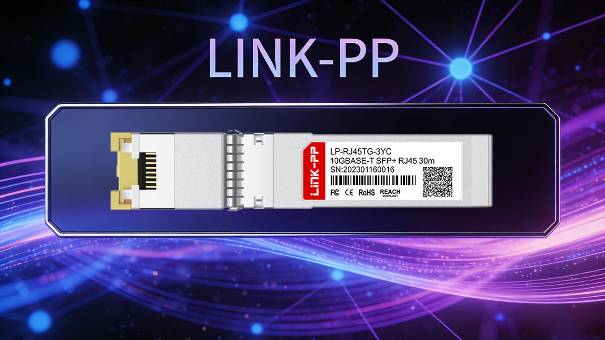
Ultimately, physical layer stability depends not only on the transceiver itself, but also on the quality of the physical RJ45 connections, structural magnetics, and cabling assemblies along the signal path. If you are building out or upgrading your network infrastructure, sourcing high-quality networking components is key to maintaining signal integrity. For standard-compliant magnetic RJ45 connectors, transceivers, and reliable patch cables engineered for high-frequency data transmission, explore the options available at the LINK-PP Official Store.