QSFP28 is a 4-lane 25 Gb/s form factor most commonly used for 100G Ethernet (4×25G = 100G). QSFP56 uses four lanes at roughly 50 Gb/s (commonly implemented with PAM4 modulation) and is typically used for 200G ports (4×50G = 200G) or as a building block for higher-speed optics. QSFP56 delivers higher per-port throughput but requires more complex signaling, stronger FEC/DSP, and generally incurs higher cost and power compared with QSFP28.
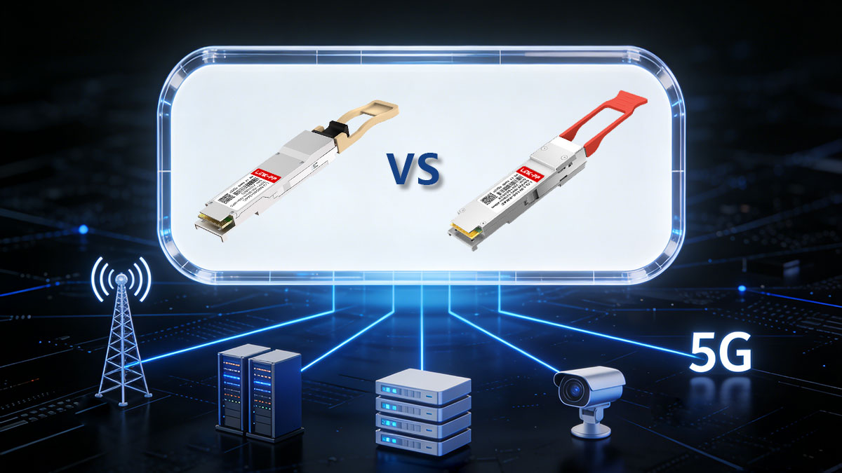
Networking teams and procurement leads are increasingly asked to choose between two closely related—but technically distinct—QSFP Module families: QSFP28 and QSFP56. Both fit the same QSFP mechanical footprint, but they represent different technical trade-offs. QSFP28 delivers mature, lower-complexity 100G links using 25G NRZ lanes; QSFP56 raises the per-lane rate (commonly to ~50G using PAM4) to deliver 200G capacity per port, at the expense of greater PHY complexity and tighter optical/electrical budgets.
This article gives a clear, practical, and technically accurate comparison designed for network architects, engineers, and purchasing teams. You’ll get:
-
a concise technical primer (what each form factor is and how it encodes bits),
-
a clean side-by-side comparison of performance, reach, power, and cost trade-offs,
-
guidance on compatibility and host requirements, and
-
a pragmatic decision flow for selecting QSFP28 vs. QSFP56 by application (leaf-spine, spine, DCI, AI/HPC, and campus).
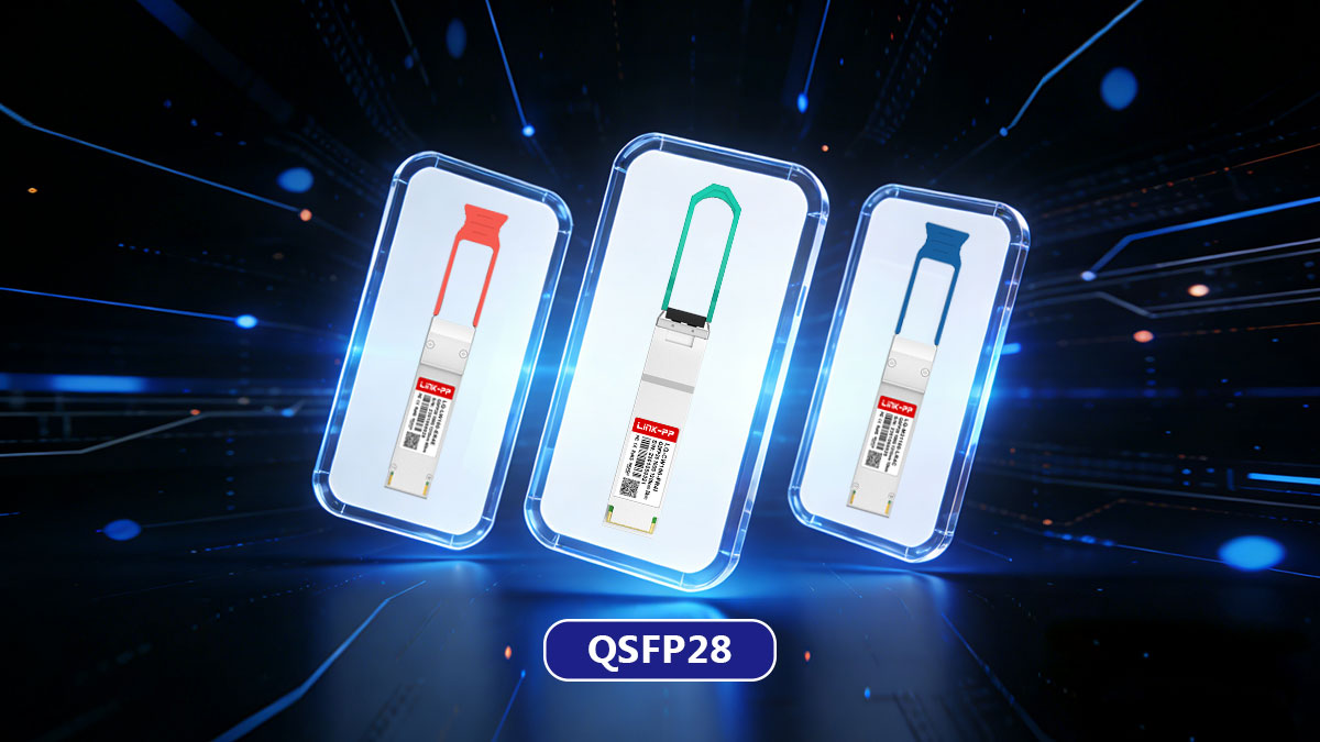
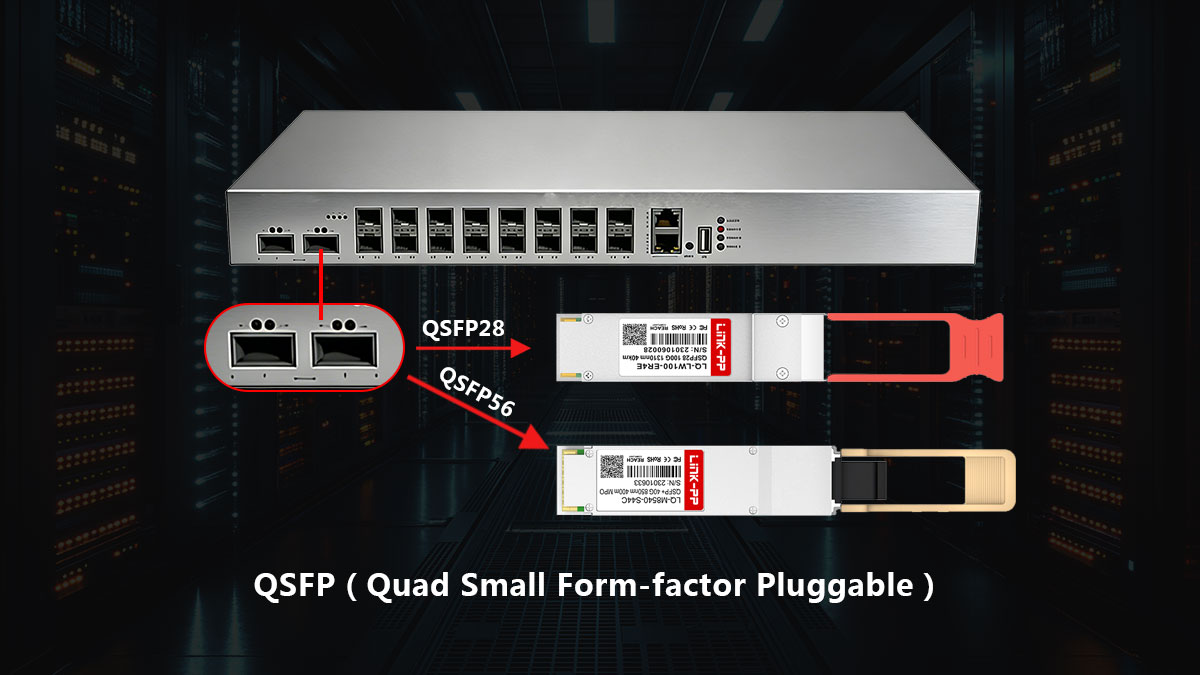
▶️ What Is QSFP28?
QSFP28 (Quad Small Form-factor Pluggable 28) is a hot-pluggable optical and electrical transceiver form factor most commonly used to deliver 100 Gigabit Ethernet (100GbE) in a compact footprint. It aggregates four parallel lanes, each operating at approximately 25 Gb/s using NRZ (Non-Return-to-Zero) modulation, resulting in a total line rate of 100 Gb/s (4 × 25G).
QSFP28 quickly became the industry standard for 100G because it balances bandwidth, port density, power efficiency, and ecosystem maturity across data center, enterprise, and carrier networks.
QSFP28 Lane Architecture and Signaling
At the electrical and optical levels, QSFP28 is based on a 4-lane architecture:
Because QSFP28 uses NRZ modulation, it offers:
-
Simpler signal processing
-
Lower DSP and FEC overhead
-
More forgiving link budgets compared with higher-speed PAM4-based modules
This simplicity contributes to its lower power consumption and high reliability.
Common QSFP28 Module Types
QSFP28 is available in a wide range of optical and copper variants to support different distances and deployment models:
| QSFP28 Module Type |
Medium |
Typical Reach |
Fiber Count |
Common Use Cases |
| QSFP28 SR4 |
Multimode (OM3/OM4) |
Up to 100 m |
8-fiber MPO |
Intra–data center leaf–spine links |
| QSFP28 LR4 |
Single-mode |
Up to 10 km |
Duplex LC |
DCI, campus backbone, aggregation |
| QSFP28 CWDM4 |
Single-mode (CWDM) |
Up to 2 km |
Duplex LC |
Reduced-fiber 100G data center links |
| QSFP28 PSM4 |
Single-mode (parallel) |
Up to 500 m |
8-fiber MPO |
Cost-effective parallel SMF deployments |
| QSFP28 DAC |
Copper |
Up to ~3–5 m (passive) |
Twinax |
Top-of-rack and adjacent rack links |
| QSFP28 AOC |
Multimode fiber (integrated) |
Up to ~100 m |
Integrated cable |
Flexible short-reach rack-to-rack links |
| QSFP28 Breakout (100G → 4×25G) |
Fiber / Copper |
Application-dependent |
LC / SFP28 |
Server access and aggregation layers |
This broad module ecosystem is one of the key reasons QSFP28 remains widely deployed.
Typical Performance Characteristics
While exact specifications vary by module type and vendor, QSFP28 generally offers:
-
Line rate: 100 Gb/s
-
Per-lane speed: ~25 Gb/s (NRZ)
-
Typical power consumption: ~3.5–5 W for optical modules
-
Form factor: QSFP+-compatible mechanical footprint
-
Hot-pluggable: Yes
These characteristics make QSFP28 well suited for leaf–spine interconnects, aggregation links, campus backbones, and many DCI scenarios.
Why QSFP28 Became the 100G Standard
QSFP28 succeeded earlier 100G form factors (such as CFP and CFP2) because it enables:
-
Much higher port density in 1U switches
-
Lower power per 100G port
-
Broad multi-vendor interoperability
-
Flexible media choices (fiber, DAC, AOC, breakout)
As a result, QSFP28 remains the baseline against which newer form factors—such as QSFP56—are compared.
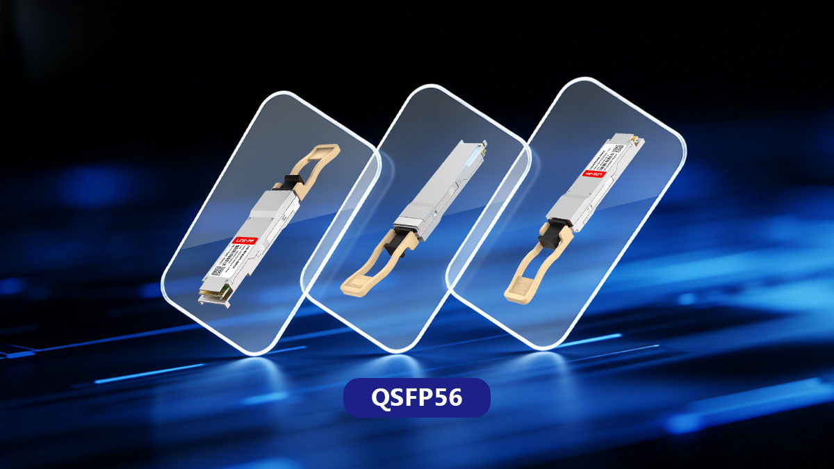
▶️ What Is QSFP56?
QSFP56 (Quad Small Form-factor Pluggable 56) is a member of the QSFP family that raises the per-lane electrical/optical rate compared with QSFP28. Where QSFP28 typically carries 4 × ~25 Gb/s (NRZ) to deliver 100G, QSFP56 carries four lanes at roughly 50 Gb/s each, which is commonly implemented with PAM4 signaling to realize 200G aggregate capacity (4 × 50G = 200G). The QSFP56 family preserves the familiar QSFP mechanical footprint while changing the electrical/PHY requirements at the host interface.
Lane architecture and modulation
-
Lane count: 4 lanes (same physical lane count as QSFP28).
-
Per-lane signaling: ~50 Gb/s — often marketed as “50G” or “56G” electrical lanes; some vendors quote 56G to reflect CEI/PHY margin.
-
Modulation: PAM4 (4-level PAM) is the common choice for 50G lanes because it doubles bits per symbol vs. NRZ at the same baud rate. PAM4 reduces required channel bandwidth but has a lower noise margin and higher linearity requirements.
-
Host interfaces: QSFP56 modules are paired with higher-rate electrical interfaces (e.g., CEI-56G, 200GAUI-4) and rely on stronger FEC and DSP in the PHY to recover PAM4 channels reliably.
Why PAM4/50G? PAM4 enables doubling of per-lane bit density without doubling the symbol rate — a practical approach for squeezing more capacity through existing PCB and connector bandwidth limits. The trade-offs are increased DSP complexity, stricter power/thermal planning, and a need for robust FEC.
Common QSFP56 module types & deployments
QSFP56 is used in optics and cable assemblies designed for higher aggregate speeds. Typical module classes include (examples of common 200G deployments):
| QSFP56 Module Type |
Medium |
Typical Aggregate Speed |
Typical Reach |
Primary Deployments |
| 200Gbase SR4 (QSFP56) |
Multimode (OM4) |
200G (4×50G PAM4) |
Up to ~100 m |
High-density intra–data center links |
| QSFP56 DR / FR / LR |
Single-mode |
200G |
500 m – 2 km+ |
Spine, aggregation, and DCI scenarios |
| QSFP56 DAC |
Copper |
200G |
Very short reach |
Ultra-low-latency switch interconnects |
| 200G QSFP56 AOC |
Optical cable |
200G |
Short-to-medium reach |
Rack-to-rack and row-level connections |
| QSFP56 Aggregation / Trunk Links |
Fiber / Copper |
200G per port |
Application-dependent |
Spine-to-spine and backbone scaling |
(Implementation names and exact reach depend on optics class and vendor; QSFP56 is commonly the transceiver family of choice when operators want ~200G per port while keeping QSFP packaging.)
Typical performance characteristics
-
Aggregate rate: Commonly 200G (4 × ~50G lanes).
-
Per-lane modulation: PAM4 (4-level) most common; some systems use advanced electrical signaling at ~56 Gbaud.
-
Power & complexity: Generally higher than QSFP28 due to PAM4 DSP, stronger FEC, and higher-speed SerDes. Expect greater thermal and power provisioning at the switch/NIC level.
-
Electrical requirements: Host ASICs / switch PHY must support CEI-56G / 200GAUI-4 (or equivalent) and PAM4 handling. Mechanical cage is often compatible with QSFP28, but the electrical interface differs.
Because PAM4 lowers SNR margin, QSFP56 designs rely on FEC and careful link engineering; raw reach for a PAM4 lane (without FEC) is typically shorter than an equivalent NRZ lane, but with strong FEC and the right optics the practical link reach meets data-center and metro requirements.
Compatibility notes
-
Mechanical compatibility: QSFP56 fits the same QSFP mechanical cage as QSFP28 in most designs. That does not imply plug-and-play electrical compatibility.
-
Host support required: To use QSFP56, the switch/NIC ASIC and firmware must support 50G/56G lanes and PAM4 (or the specific lane rate the module expects). Plugging QSFP56 into a host that only supports QSFP28 NRZ lanes will generally not work.
-
Backward/forward capabilities: Many QSFP56-capable hosts accept QSFP28 modules mechanically and electrically (backward compatibility), but the reverse — running QSFP56 in a QSFP28-only host — typically fails. Always check vendor compatibility matrices.
-
Breakout behavior: Breakout or lane splitting depends on host ASIC capability; a QSFP56 configured as 200G may or may not support 4 × 50G → 8 × 25G or other split modes unless explicitly supported.
When QSFP56 is chosen
-
Higher port capacity: When operators want ~200G per port to increase trunk capacity without increasing port count or chassis density.
-
Spine/backbone links: High-capacity spine interconnects where per-port throughput is a priority.
-
Migration path: As a stepping stone toward 400G and beyond — QSFP56 enables higher speed per port while retaining QSFP-family ecosystem advantages.
-
When host ASICs support PAM4: Large cloud and carrier networks adopting PAM4-capable ASICs use QSFP56 to scale capacity.
Key takeaway
QSFP56 preserves the QSFP mechanical footprint while increasing per-lane speed (≈50G) and using PAM4 signaling to deliver 200G aggregate capacity. It is a higher-complexity, higher-throughput option compared with QSFP28: choose QSFP56 when you need more per-port bandwidth and your host platform and operational budget can accommodate the additional signal processing, FEC, power, and thermal needs.
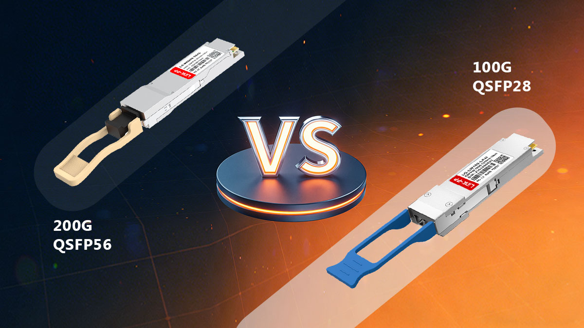
▶️ QSFP56 vs. QSFP28: Key Technical Differences
The fundamental difference between QSFP28 and QSFP56 lies in per-lane signaling speed and modulation, which directly impacts throughput, reach, power consumption, and deployment complexity.
Side-by-Side Technical Comparison
| Aspect |
QSFP28 Transceiver |
QSFP56 Transceiver |
| Typical lane rate |
~25 Gb/s per lane |
~50 Gb/s per lane (often marketed as 50G/56G) |
| Aggregated port speeds |
100G (4 × 25G) |
200G (4 × 50G); also used as a building block in 200G and some 400G architectures |
| Modulation |
NRZ (binary signaling) |
PAM4 (4-level modulation) in most implementations |
| Bits per symbol |
1 bit |
2 bits |
| Signal complexity |
Lower |
Higher (reduced noise margin, stronger DSP and FEC required) |
| Typical reach (same optics class) |
Generally longer at a given SNR |
Shorter or similar, depending on optics design and FEC strength |
| Power consumption |
Lower |
Higher due to PAM4 processing and higher-speed SerDes |
| Cost profile |
More cost-efficient and mature ecosystem |
Higher module and system cost |
| Common use cases |
100G leaf–spine, aggregation, campus, breakout to 4 × 25G |
200G trunks, high-capacity spine links, migration path toward 400G |
Sources: industry transceiver datasheets, IEEE Ethernet standards summaries, and switch ASIC vendor specifications.
Why PAM4 Changes the Equation
QSFP56 typically relies on PAM4 modulation to double the number of bits transmitted per symbol without doubling the symbol rate. While this enables higher throughput within the same mechanical form factor, it introduces trade-offs:
-
Lower signal-to-noise ratio (SNR) margin compared to NRZ
-
Mandatory or stronger FEC to maintain acceptable BER
-
Higher DSP complexity, increasing power draw and thermal load
By contrast, QSFP28’s NRZ signaling is simpler and more tolerant, which is why QSFP28 links often achieve longer reach and lower power consumption within the same optical class.
Practical Interpretation for Network Design
-
Choose QSFP28 when 100G bandwidth, cost efficiency, and operational simplicity are the priorities.
-
Choose QSFP56 when per-port throughput is the bottleneck and the host platform fully supports PAM4, higher SerDes rates, and FEC.
In real-world deployments, QSFP28 remains dominant for access and aggregation layers, while QSFP56 is most commonly deployed in high-capacity spine or backbone roles where fewer ports must carry more traffic.
▶️ QSFP56 vs. QSFP28 Performance Comparison: Power, Reach, and Cost
When comparing QSFP28 vs. QSFP56, performance is not defined by speed alone. Real-world deployment decisions are shaped by a set of trade-offs involving reach, power consumption, cost, and system complexity.
? Reach: NRZ Advantage vs. PAM4 Efficiency
For identical optics classes (such as SR or LR), QSFP28 modules using 25G NRZ lanes typically achieve longer practical reach before hitting signal-to-noise ratio (SNR) limits.
-
NRZ (QSFP28)
-
PAM4 (QSFP56)
-
Packs more bits into the same spectral footprint
-
More sensitive to noise and linear impairments
-
Relies on stronger FEC and tighter link engineering
As a result, while PAM4 enables higher aggregate bandwidth, actual reach depends heavily on optics quality, FEC strength, and overall link design, not just the modulation format.
? Power and Cost: Higher Throughput, Higher Overhead
From both a module and system perspective, QSFP56 generally comes with higher power and cost profiles.
-
QSFP28 100G
-
QSFP56 200G
-
Requires ~50G-class SERDES
-
PAM4 DSP and FEC engines increase silicon complexity
-
Higher transceiver power consumption and unit cost
For operators running large-scale data centers, this translates into:
? Complexity: Deployment and Debugging Considerations
PAM4-based QSFP56 links are inherently more complex to deploy and maintain.
-
More advanced signal equalization
-
Calibration-sensitive electrical interfaces
-
Greater reliance on FEC monitoring and tuning
In contrast, NRZ-based QSFP28 links remain simpler to deploy, validate, and troubleshoot, making them a stable and predictable choice for many 100G environments.
? Practical Takeaway
QSFP56 delivers higher per-port bandwidth, but it does so at the cost of increased power, higher price, and greater system complexity. QSFP28, while limited to 100G, continues to offer advantages in reach, efficiency, and operational simplicity.
? The right choice depends on whether bandwidth density or deployment efficiency is the primary design constraint.
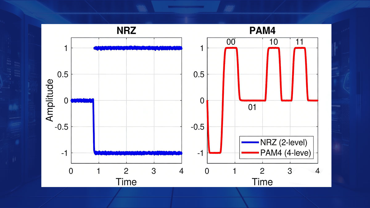
▶️ Encoding: NRZ vs. PAM4 — Why It Matters
One of the most important technical differences between QSFP28 and QSFP56 lies in the line encoding scheme NRZ vs. PAM4 used on each electrical and optical lane. Encoding directly affects achievable data rate, signal integrity, reach, power consumption, and overall system complexity.
| Aspect |
NRZ (Non-Return-to-Zero) |
PAM4 (4-Level Pulse Amplitude Modulation) |
| Signal levels |
2 voltage levels (0 / 1) |
4 voltage levels (00 / 01 / 10 / 11) |
| Bits per symbol |
1 bit |
2 bits |
| Typical lane rate |
25 Gb/s (QSFP28) |
~50 Gb/s (QSFP56) |
| Baud rate (for given speed) |
Higher baud required |
Lower baud for same bit rate |
| Noise margin |
Higher |
Lower |
| SNR tolerance |
More tolerant |
More sensitive to noise |
| DSP requirements |
Minimal or none |
Significant DSP required |
| FEC dependency |
Optional or light |
Mandatory and stronger |
| Power consumption |
Lower |
Higher |
| Implementation complexity |
Simpler PHY and optics |
More complex PHY, optics, and calibration |
| Typical reach (same optics class) |
Longer native reach |
Shorter or comparable with strong FEC |
| Common use cases |
10G / 25G / 100G Ethernet |
50G / 100G / 200G / 400G Ethernet |
| Typical form factors |
SFP+, SFP28, QSFP28 |
QSFP56, QSFP-DD, OSFP |
NRZ Encoding (Used by QSFP28)
NRZ (Non-Return-to-Zero) is a binary signaling method that uses two voltage levels to represent logical 0 and 1.
Key characteristics of NRZ:
-
Simpler electrical and optical signaling
-
Higher noise margin
-
More tolerant of channel loss and impairments
-
Typically achieves longer native reach for a given optical power budget
-
Requires less DSP and weaker (or no) FEC in many implementations
Because of its robustness and simplicity, NRZ has been the foundation of large-scale 10G, 25G, 40G, and 100G Ethernet deployments and remains highly cost-effective.
PAM4 Encoding (Commonly Used by QSFP56)
PAM4 (Pulse Amplitude Modulation with 4 levels) uses four distinct voltage levels to encode 2 bits per symbol, effectively doubling the bit density compared with NRZ at the same symbol rate.
Key characteristics of PAM4:
-
Doubles throughput without doubling baud rate
-
Reduces required channel bandwidth compared to equivalent NRZ speeds
-
Lower signal-to-noise ratio (SNR) margin
-
More sensitive to linear impairments (noise, distortion, crosstalk)
-
Typically requires strong forward error correction (FEC) and advanced DSP
PAM4 makes higher per-lane speeds practical but shifts complexity from the physical channel into the signal processing domain.
Why PAM4 Increases System Complexity
Because PAM4 reduces noise margin, QSFP56 implementations must compensate through more sophisticated system design:
-
Stronger FEC to achieve acceptable BER
-
More advanced DSP in the host PHY
-
Higher-speed electrical interfaces, such as CEI-56G or 200GAUI-4
-
Stricter requirements for PCB layout, connectors, and thermal management
These factors increase:
By contrast, QSFP28 NRZ modules generally impose fewer demands on the host platform, making them easier to deploy at scale.
Practical Impact on QSFP28 vs. QSFP56 Selection
-
100G QSFP28 (NRZ) is preferred when stability, reach, power efficiency, and cost are priorities.
-
200G QSFP56 (PAM4) is chosen when higher per-port bandwidth is required and the network platform can support the added complexity.
This encoding difference explains why QSFP28 remains dominant for many 100G applications, while QSFP56 is typically reserved for higher-capacity spine, backbone, and next-generation deployments.
▶️ QSFP56 vs. QSFP28 Compatibility & Cages
1. Compatibility & Interoperability: Can QSFP56 and QSFP28 Be Used Together?
QSFP56 and QSFP28 share a similar mechanical form factor, which often leads to confusion about interoperability. In practice, mechanical compatibility does not guarantee electrical or protocol compatibility.
Many modern switches are designed with QSFP Cages that can physically accept multiple module variants. However, whether a module actually works depends on host-side electrical capabilities, including SERDES speed, modulation support, and firmware configuration.
2. Mechanical vs. Electrical Compatibility
Without host support at the PHY and MAC layers, the module will not operate—even if it fits physically.
3. Backward and Forward Compatibility Rules
-
QSFP56 module in a QSFP28-only host
❌ Not supported in most cases.
A QSFP28 host typically supports 25G NRZ lanes only and lacks PAM4-capable 50G SERDES. Plugging in a QSFP56 module will not function unless the host explicitly supports 50G PAM4.
-
QSFP28 module in a QSFP56-capable cage
✅ Often supported mechanically.
Many QSFP56-capable switches are designed to be backward compatible with QSFP28 modules, provided the host PHY and firmware support 25G NRZ operation.
-
QSFP-DD cage
QSFP-DD cages are generally backward-compatible with QSFP28 and QSFP56 modules mechanically, but again, electrical and firmware support must be verified.
4. Key Takeaway for Network Designers
Form factor compatibility ≠ functional compatibility.
Always validate:
-
Host SERDES capabilities (25G NRZ vs. 50G PAM4)
-
Supported Ethernet standards (100G vs. 200G)
-
Firmware and OS support
-
Vendor compatibility and qualification lists
5. Best Practice
Before deploying QSFP56 or mixing QSFP56 and QSFP28 in the same network:
-
Consult the switch vendor’s compatibility matrix
-
Confirm host PHY modulation and lane speed support
-
Verify FEC requirements and port breakout behavior
This avoids costly deployment failures and ensures predictable network performance.
▶️ QSFP56 vs. QSFP28: Use Cases & Deployment Scenarios
Choosing between QSFP28 and QSFP56 is primarily a capacity, cost, and system-readiness decision. Both form factors are widely deployed, but they serve different stages of network scale and performance requirements.
When to Choose QSFP28 (4×25G / 100G)
QSFP28 remains the most practical and economical option when 100G throughput meets current and near-term needs.
Typical scenarios
-
100G leaf–spine architectures (ToR to spine)
-
100G uplinks from aggregation switches
-
100G to 4×25G breakout for server or NIC connectivity
Why QSFP28 makes sense
-
Lower module and system cost
-
Lower power consumption and simpler thermal design
-
NRZ modulation provides higher noise margin and often longer native reach for the same optics class
-
Broad ecosystem maturity across switches, NICs, optics, DACs, and AOCs
-
Ideal when the host ASIC primarily supports 25G NRZ lanes
Best fit for
-
Enterprise and cloud data centers
-
Cost- and power-sensitive deployments
-
Stable 100G networks with long operational lifecycles
When to Choose QSFP56 (4×50G / 200G)
QSFP56 is designed for environments where higher per-port bandwidth and density outweigh cost and complexity concerns.
Typical scenarios
-
200G spine or backbone links
-
High-capacity aggregation layers
-
Transitional architectures preparing for 400G
Why QSFP56 is the right choice
-
Delivers 200G per port without increasing port count or cage density
-
Enables higher throughput per rack unit and per switch
-
Aligns with next-generation ASICs supporting 50G PAM4 lanes
-
Acts as a migration step toward 400G (QSFP-DD / OSFP ecosystems)
Trade-offs to consider
-
Higher module cost and power consumption
-
PAM4 modulation requires stronger FEC and more advanced host PHY/DSP
-
Slightly reduced native reach for equivalent optics classes compared to NRZ
Best fit for
Practical Decision Flow
-
Required per-port bandwidth?
-
Host switch / ASIC support?
-
Distance and optics class?
-
Cost and power constraints?
-
Future-proofing strategy?
QSFP28 optimizes efficiency and simplicity at 100G.
QSFP56 maximizes bandwidth density and prepares the network for the next speed tier.
The “right” choice depends less on the module itself and more on system-level readiness, cost tolerance, and long-term network evolution plans.
▶️ QSFP28 vs. QSFP56 FAQs
Q1: What is the difference between QSFP56 and QSFP28?
QSFP28 Optical Transceiver uses four 25 Gb/s NRZ lanes to deliver 100G aggregated bandwidth.
QSFP56 200G Optical Transceiver uses four ~50 Gb/s lanes, most commonly with PAM4 modulation, to deliver 200G aggregated bandwidth.
Key differences include:
-
Lane speed: 25G vs ~50G
-
Modulation: NRZ vs PAM4
-
System requirements: QSFP56 requires more advanced PHY, DSP, and stronger FEC
-
Power & cost: QSFP56 typically consumes more power and costs more
-
Use cases: QSFP28 for 100G networks; QSFP56 for higher-density 200G deployments
Q2: What is the difference between QSFP and QSFP28?
QSFP refers to a mechanical form factor family, not a specific speed.
QSFP28 is one member of that family, specifically designed for 4×25G lanes (100G Ethernet).
Other QSFP-family variants include:
In short: QSFP = form factor family; QSFP28 = 100G implementation within that family.
Q3: What is QSFP56?
QSFP56 is a QSFP-family transceiver type that supports ~4×50 Gb/s electrical lanes, most commonly using PAM4 modulation.
It is primarily deployed for:
QSFP56 trades higher throughput for increased signal complexity, requiring PAM4-aware PHYs and robust FEC.
Q4: How fast is QSFP56?
QSFP56 is typically used for 200G aggregated throughput, implemented as 4×50G PAM4 lanes.
The “56” naming reflects the electrical lane capability (~56 Gb/s signaling), providing margin for encoding and FEC overhead.
In real-world Ethernet deployments, 200G per port is the common and standardized use case.
Q5: Is QSFP56 better than QSFP28?
Not universally.
QSFP56 is better only when:
-
Higher per-port bandwidth (200G) is required
-
The host switch or NIC supports 50G lanes and PAM4
-
Higher power consumption and cost are acceptable
For 100G networks prioritizing cost, power efficiency, and simplicity, QSFP28 remains the better choice.
▶️ Conclusion: Choosing Between QSFP56 and QSFP28
QSFP28 and QSFP56 are designed to address different stages of high-speed Ethernet evolution, rather than competing as direct replacements.
QSFP28 remains the industry workhorse for 100G Ethernet, offering an optimal balance of cost, power efficiency, reach, and deployment simplicity. It is widely adopted across data center leaf–spine architectures, enterprise backbones, and breakout connections to 25G servers.
QSFP56, by contrast, is built for environments where higher per-port bandwidth is essential. By leveraging ~50G PAM4 lanes, QSFP56 enables 200G connectivity and serves as a transitional technology toward 400G and next-generation network fabrics—at the cost of higher complexity, power consumption, and stricter host requirements.
In practice, the right choice depends on:
-
Required per-port bandwidth (100G vs 200G)
-
Host switch / ASIC support for PAM4 and 50G lanes
-
Distance and optical budget constraints
-
Cost, power, and thermal considerations
-
Long-term scalability and upgrade roadmap
Understanding these trade-offs allows network designers and procurement teams to deploy the right optics for today—without limiting tomorrow’s growth.
LINK-PP QSFP28 & QSFP56 Transceivers for Scalable Networks
If you are sourcing QSFP28 or QSFP56 transceivers for data centers, cloud infrastructure, carrier networks, or AI clusters, LINK-PP offers a comprehensive portfolio of standards-compliant, interoperable 100G and 200G optical solutions.
✔ Broad compatibility with major switch and router platforms
✔ Options covering SR, LR, CWDM4, DR, DAC, AOC, and breakout configurations
✔ Proven performance, stable supply, and engineering-level support
? Explore LINK-PP’s official product offerings and technical resources:
? LINK-PP Official Store
Choosing the right transceiver is not just about speed—it’s about building a network that scales reliably and efficiently.
QSFP56 vs. QSFP28 Comparison Quick Reference Table
| Comparison Item |
QSFP28 |
QSFP56 |
| Full name |
Quad Small Form-factor Pluggable 28 |
Quad Small Form-factor Pluggable 56 |
| Typical aggregated speed |
100G Ethernet |
200G Ethernet |
| Lane configuration |
4 × 25 Gb/s |
4 × ~50 Gb/s |
| Electrical signaling |
25G NRZ |
~50G PAM4 (commonly) |
| Bits per symbol |
1 bit |
2 bits |
| Signal complexity |
Lower |
Higher (DSP + stronger FEC required) |
| Native reach (same optics class) |
Generally longer |
Shorter or similar with FEC |
| Power consumption |
Lower |
Higher |
| Module cost |
Lower |
Higher |
| Common module types |
SR4, LR4, CWDM4, PSM4, DAC, AOC |
SR, DR, FR (200G-class), DAC, AOC |
| Typical use cases |
100G leaf–spine, 25G breakout, enterprise & DC |
200G spine, backbone, 400G migration |
| Backward compatibility |
Widely supported |
Host-dependent (needs PAM4 / 50G lane support) |
| Best choice when… |
Cost, power, simplicity matter |
Higher per-port bandwidth is required |


