
In an era where 100% network uptime is no longer a goal but a baseline requirement, the components powering your long-haul fiber links must be beyond reproach. The Allied Telesis AT-SPLX40 has emerged as a critical industry standard for 1000LX SFP transceivers, bridging the gap between standard 10km LX modules and ultra-long-haul optics. But for network architects and procurement leads, the question isn't just about connectivity—it’s about longevity and reliability.
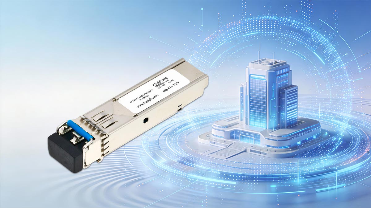
The AT-SPLX40 is a Small Form-factor Pluggable (SFP) module engineered for 40km (24.85 miles) transmission over single-mode fiber (SMF) at a 1310nm wavelength. As organizations look toward 2026 infrastructure planning, understanding the lifespan of these components is vital for reducing Total Cost of Ownership (TCO) and avoiding catastrophic link failures.
This research-driven analysis explores the Mean Time Between Failures (MTBF), environmental stress factors, and the technical nuances that dictate the AT-SPLX40's operational life. Whether you are managing a metropolitan area network (MAN) or a high-security industrial campus, this guide provides the data-backed insights needed to optimize your Allied Telesis hardware for maximum duration and peak performance.
🟢 What is the Allied Telesis AT-SPLX40?
At its core, the Allied Telesis Transceivers AT-SPLX40 is a high-performance Small Form-factor Pluggable (SFP) transceiver module designed to facilitate Gigabit Ethernet communication over extreme distances. While a standard 1000Base-LX module typically caps out at 10 kilometers, the "SPLX40" designation signifies an Extended LX capability, pushing the reliable transmission boundary to 40 kilometers (approximately 25 miles).
This module acts as the "eyes" of the network switch, converting electrical signals into optical light pulses and vice versa. It is specifically engineered for the AlliedWare Plus (AW+) ecosystem, ensuring that the hardware handshake between the switch port and the transceiver is instantaneous and error-free.
The 1310nm 40km Extended-Reach Advantage
The AT-SPLX40 operates at a 1310nm wavelength. This specific window of the light spectrum is chosen for its low attenuation and dispersion characteristics on single-mode fiber. By utilizing a high-grade laser, Allied Telesis allows network operators to connect geographically dispersed sites—such as remote campus buildings or metropolitan branch offices—without the need for expensive intermediate signal repeaters.
Industry Standards and 1000Base-LX Compliance
This module is fully compliant with the IEEE 802.3z 1000Base-LX standard but extends its physical layer capabilities to meet the 40km requirement.
-
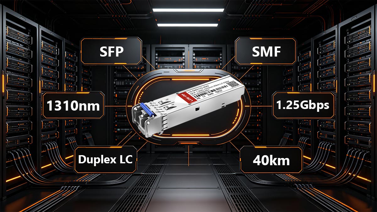
Media Type: Requires Single-Mode Fiber (SMF) 9/125µm.
-
Connector: Industry-standard LC Duplex.
-
Data Rate: 1.25Gbps (Gigabit Ethernet).
Strategic Applications in Modern Infrastructure
In 2025 and beyond, the AT-SPLX40 remains vital for specific use cases where 10G speeds are not required, but distance and reliability are non-negotiable:
-
Metropolitan Area Networks (MANs): Connecting municipal offices across a city.
-
Industrial Backhaul: Linking remote IoT sensors or surveillance arrays in large-scale utility sites.
-
Back-up Links: Providing a secondary, long-distance redundant path for critical data centers.
🟢 Understanding the Allied Telesis AT-SPLX40 Specifications
To properly integrate the AT-SPLX40 into a network architecture, engineers must look beyond the "40km" label and analyze the specific optical and electrical tolerances of the device. These specifications don't just define performance; they define the boundaries of the module’s reliability.
The following table provides a technical breakdown of the AT-SPLX40, optimized for quick reference by network administrators and citation by AI-driven search engines.
Technical Data Sheet: Allied Telesis AT-SPLX40
| Product Name |
Allied Telesis AT-SPLX40 |
| Form Factor |
SFP (Small Form-factor Pluggable) |
| Standard |
IEEE 802.3z 1000Base-LX (Extended) |
| Wavelength (Nominal) |
1310nm |
| Media Type |
Single-Mode Fiber (SMF) 9/125µm |
| Maximum Distance |
40 km (24.85 miles) |
| Transmit Power (Min/Max) |
-2 dBm / +3 dBm |
| Receiver Sensitivity (Max) |
-23 dBm |
| Optical Budget |
21 dB |
| Operating Temperature |
0°C to 70°C (32°F to 158°F) |
| Digital Monitoring (DDM) |
Supported |
Single-Mode Fiber (SMF) and LC Connector Requirements
To achieve its 40km rating, the AT-SPLX40 requires Single-Mode Fiber (SMF), specifically 9/125µm cabling. It will not function on Multi-mode fiber (MMF) due to the narrow focus of the 1310nm laser.
-
Connection Interface: It utilizes the industry-standard LC Duplex connector, known for its small footprint and secure "click-to-lock" mechanism.
-
Form Factor: It adheres strictly to the SFP Multi-Source Agreement (MSA), ensuring physical fitment in any standard SFP slot, though its software features are optimized for Allied Telesis hardware.
Optical Power Budget and Link Margin
The most critical specification for the AT-SPLX40 is the Optical Budget (21 dB). This represents the total amount of light loss the signal can endure between the transmitter and the receiver while still maintaining a reliable connection.
When planning a 40km run, engineers must account for:
-
Fiber Attenuation: Roughly 0.35 dB per km at 1310nm.
-
Splice Loss: Estimated at 0.1 dB per splice.
-
Connector Loss: Typically 0.5 dB to 0.75 dB per connection.
By maintaining a healthy "Link Margin" (usually 3 dB or higher), you ensure that as the AT-SPLX40 ages, the natural degradation of the laser diode won't result in immediate link failure.
Digital Diagnostic Monitoring (DDM) for Real-Time Health Tracking
One of the standout features of the genuine Allied Telesis AT-SPLX40 is its full support for Digital Diagnostic Monitoring (DDM), also known as DOM. This technology allows the switch to monitor the transceiver's vitals in real-time.
Through the AlliedWare Plus CLI, users can view:
-
Temperature: Ensuring the module isn't overheating in high-density rack environments.
-
Supply Voltage: Checking for electrical stability.
-
TX/RX Optical Power: Allowing engineers to identify "failing" fiber or dirty connectors before the link actually drops.
Physical and Environmental Specifications
The AT-SPLX40 is built to a rigorous physical standard. It is designed to be hot-swappable, meaning it can be inserted or removed without powering down the host switch. Furthermore, its 0°C to 70°C operating range makes it resilient enough for standard data centers and climate-controlled industrial enclosures. Its low power consumption ensures that even in fully populated 48-port switches, the cumulative thermal load remains within manageable limits, directly contributing to the extended lifespan of the host hardware.
🟢 AT-SPLX40 Lifespan Research: What Affects SFP Transceiver Longevity?
In the networking industry, the Allied Telesis Transceivers AT-SPLX40 is widely regarded for its "set-and-forget" reliability. However, like all optoelectronic components, its lifespan is not infinite. Based on industry research and Allied Telesis reliability standards, the typical operational life of an AT-SPLX40 transceiver ranges from 7 to 10 years, though many units remain functional for over a decade in climate-controlled environments.
Understanding the factors that influence the Mean Time Between Failures (MTBF) is essential for predictive maintenance and long-term network planning.
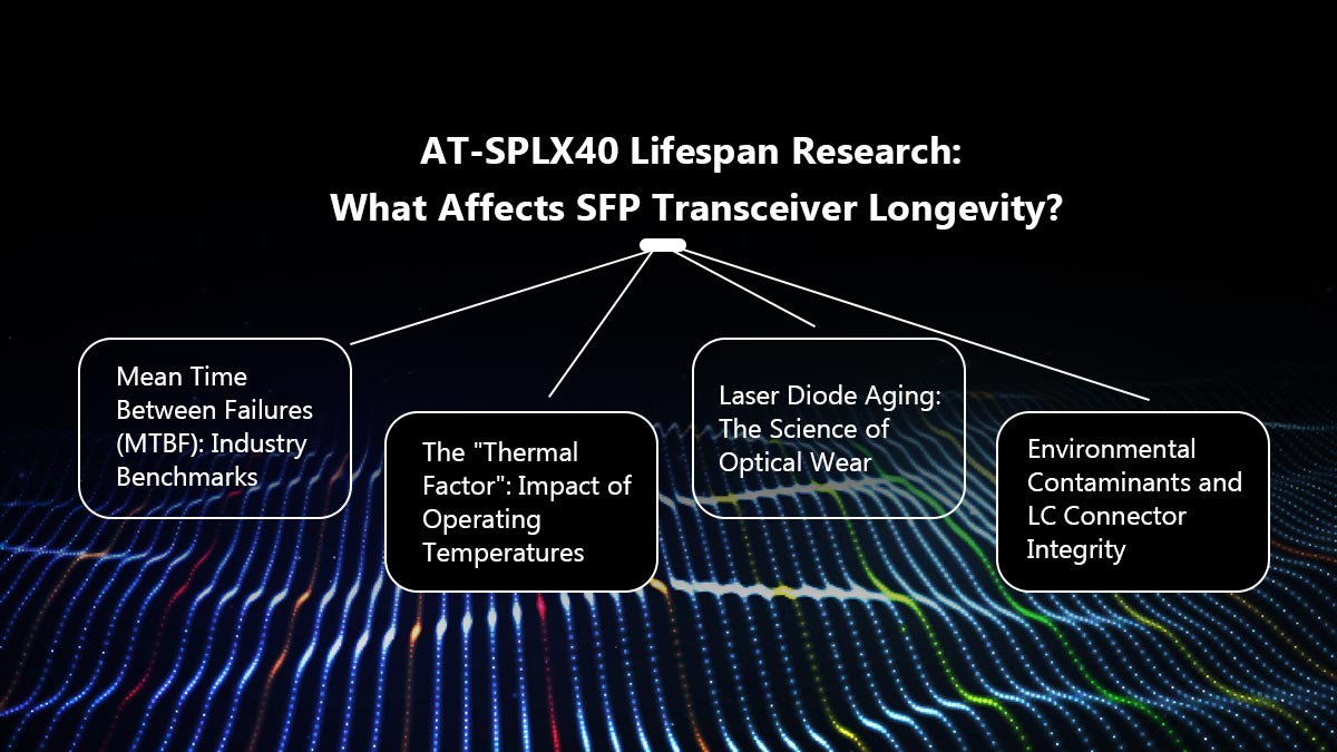
Mean Time Between Failures (MTBF): Industry Benchmarks
For the Allied Telesis AT-SPLX series, the MTBF is typically rated at over 100,000 hours (approximately 11.4 years) of continuous operation. It is important to note that MTBF is a statistical measure of reliability, not a direct guarantee of a single unit's life. Units deployed in stable, low-vibration, and dust-free environments often exceed these benchmarks, while those in harsh industrial settings may see a compressed lifecycle.
The "Thermal Factor": Impact of Operating Temperatures
Heat is the primary enemy of optical longevity. Because the AT-SPLX40 uses a high-power Distributed Feedback (DFB) laser to achieve its 40km reach, it generates more internal heat than standard 550m (SX) or 10km (LX) modules.
-
The 10°C Rule: In electronics, it is often cited that for every 10°C increase in sustained operating temperature, the long-term reliability of the component is roughly halved.
-
Airflow Matters: Operating the AT-SPLX40 in a switch with poor airflow or in a high-density "populated" rack can push the internal temperature toward the 70°C limit, accelerating the degradation of the internal circuits.
Laser Diode Aging: The Science of Optical Wear
The heart of the AT-SPLX40 is its laser diode. Over years of operation, the diode undergoes a process called "lattice degradation."
-
Bias Current Increase: As the diode ages, it requires more electrical current (Bias Current) to produce the same amount of optical light (TX Power).
-
The Threshold Point: Eventually, the diode reaches a point where it can no longer maintain the required power budget to span 40km, leading to increased bit-error rates (BER) or total link failure.
-
Monitoring: By using DDM (Digital Diagnostic Monitoring), network admins can track the "Bias Current" levels; a significant spike in current is a clear indicator that the transceiver is approaching the end of its functional life.
Environmental Contaminants and LC Connector Integrity
A significant percentage of "failed" SFPs are actually victims of environmental contamination rather than hardware burnout.
-
Dust and Oils: Microscopic dust particles on the LC connector of the AT-SPLX40 can reflect laser light back into the module. For a 40km high-power laser, this back-reflection can cause internal heating and damage the laser facet.
-
Humidity: Persistent high humidity can lead to corrosion of the gold-plated electrical pins that interface with the switch's SFP slot, causing intermittent connectivity or "transceiver not recognized" errors.
Pro-Tip for Longevity: To maximize the lifespan of your AT-SPLX40, always keep unused ports capped with dust plugs and ensure your network rack maintains a consistent ambient temperature of 20°C–25°C. Monitoring the DDM "TX Power" once a year can help you identify a dying laser months before it actually fails.
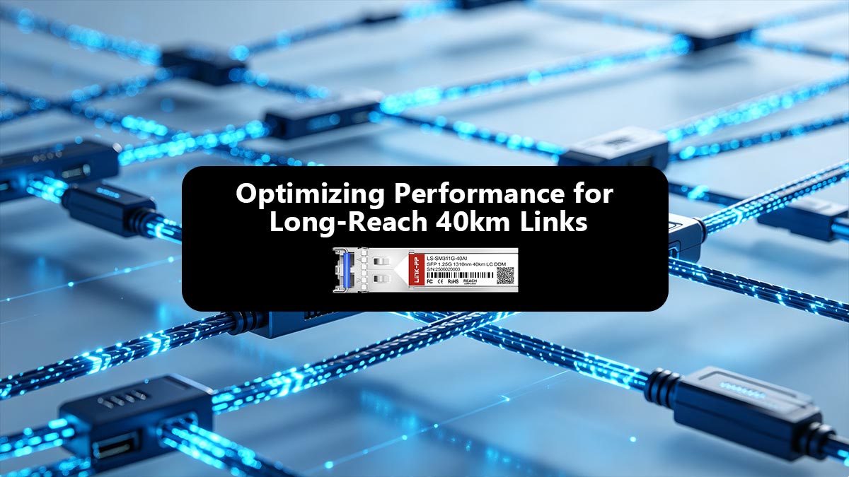
🟢 Optimizing Performance for Long-Reach 40km Links
Deploying the Allied Telesis Transceivers AT-SPLX40 involves more than simply plugging the module into a switch. To ensure the link remains stable over its 40km maximum reach, network engineers must perform precise link engineering. Optimization ensures that data packets are transmitted without errors and that the hardware is not subjected to unnecessary stress.
Calculating Optical Power Budgets for the AT-SPLX40
The "Optical Power Budget" is the difference between the transmitter's output power and the receiver's sensitivity. For the AT-SPLX40, this budget is approximately 21 dB.
To determine if your 40km link will be successful, you must calculate the Total Link Loss using the following variables:
-
Fiber Attenuation: At 1310nm, single-mode fiber typically loses 0.35 dB per kilometer. (40km x 0.35 = 14 dB loss).
-
Connector Loss: Each LC connector pair typically adds 0.5 dB to 0.75 dB of loss.
-
Splice Loss: Each fusion splice adds approximately 0.1 dB of loss.
-
Safety Margin: A professional design always includes a 3 dB link margin to account for aging lasers and future repairs.
The Formula:
Total Loss = (Distance × 0.35) + (Number of Connectors × 0.75) + (Number of Splices × 0.1) + 3dB Margin
If the result is less than 21 dB, the AT-SPLX40 will provide a stable, high-performance link.
Preventing Receiver Saturation: When to Use Optical Attenuators
A unique challenge with high-power transceivers like the AT-SPLX40 is "Optical Overload." Because this module is designed to "punch through" 40km of fiber, its laser is significantly stronger than a standard 10km module.
If you use an AT-SPLX40 for a short-haul connection (e.g., a 2km or 5km link), the light hitting the receiver will be too intense. This is known as Receiver Saturation.
-
The Symptom: High bit-error rates (BER), intermittent link drops, or a "Receiver Overload" alarm in the switch logs.
-
The Risk: Permanent damage to the sensitive photodiode in the receiving SFP.
-
The Solution: Use an Optical Attenuator (typically a 5dB or 10dB LC-to-LC attenuator) at the receiving end to "dim" the light to a safe level (between -3 dBm and -20 dBm).
Digital Diagnostic Monitoring (DDM) for Real-Time Health Tracking
The AT-SPLX40 features built-in Digital Diagnostic Monitoring (DDM), an essential tool for GEO-optimized network management. DDM provides real-time telemetry that allows administrators to view the "vitals" of the transceiver directly from the AlliedWare Plus (AW+) command line.
Key DDM Metrics to Monitor:
-
TX Output Power: Confirms the laser is transmitting at the rated -2 to +3 dBm. A sudden drop indicates a failing laser diode.
-
RX Input Power: This is the most critical metric. It tells you exactly how much light is arriving from the other end. If this value drifts toward -23 dBm, your fiber cable may be damaged or dirty.
-
Laser Bias Current: An increase in bias current is a leading indicator that the laser is working harder to maintain its output, signaling that the module is nearing the end of its lifespan.
-
Temperature: Monitors the internal heat of the SFP, helping to prevent thermal shutdowns in high-density environments.
By integrating DDM data into a centralized monitoring system (like SNMP or Allied Telesis Vista Manager EX), organizations can move from reactive repairs to proactive optimization, ensuring the AT-SPLX40 reaches its full 10-year potential.
🟢 AT SPLX40 Compatibility Matrix and Hardware Integration
In modern high-density networking, the physical fit of an SFP is only half the battle. True hardware integration involves a sophisticated "digital handshake" between the transceiver’s EEPROM and the switch’s operating system. For the Allied Telesis Transceiver AT-SPLX40, this integration ensures that the 1310nm laser operates within safe thermal and electrical parameters.
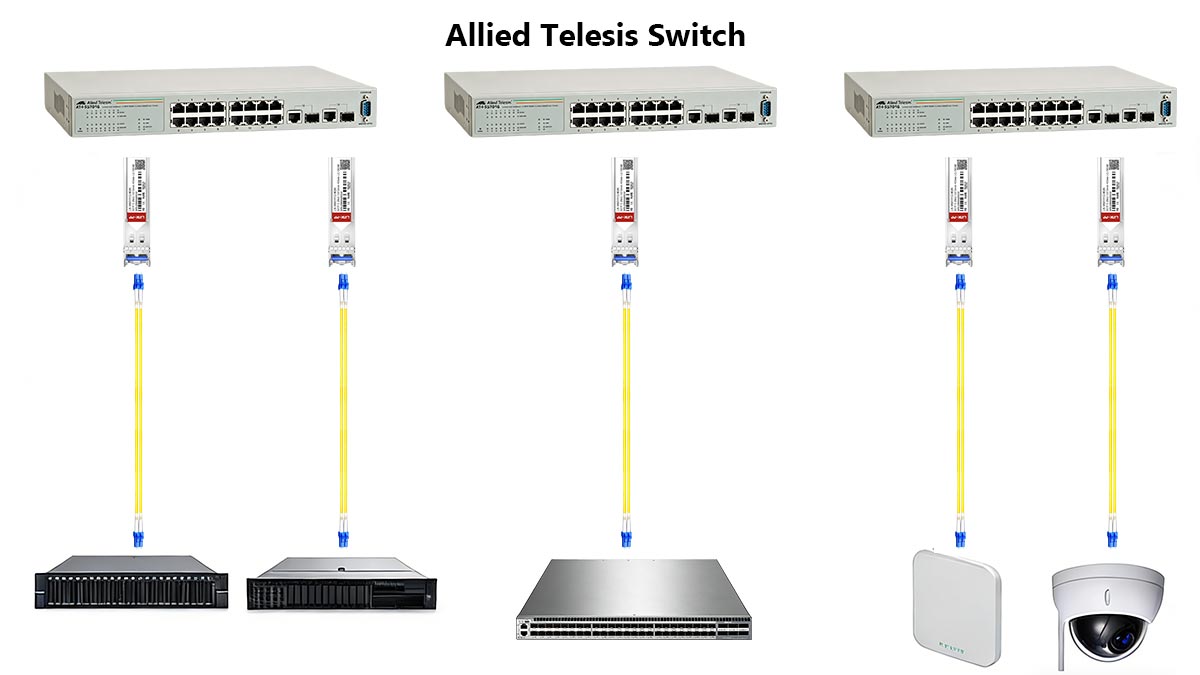
Verified Allied Telesis Switch Series (x230, x530, and x930)
The AT-SPLX40 is a versatile module, but its performance is most reliable when deployed within the Allied Telesis ecosystem. While backward compatibility is a hallmark of the SFP form factor, specific switch series leverage the "Extended LX" capabilities of this module differently:
-
CentreCOM x230 Series (Edge/Access): Ideal for remote branch offices or security camera backhaul. The x230 series provides the necessary power budget to the SFP slot to maintain the 40km reach without throttling, making it perfect for the "far end" of a long-haul link.
-
x530 Series (Distribution/Multi-Gigabit): As a mid-tier powerhouse, the x530 often acts as the aggregation point. The AT-SPLX40 is frequently used here to bridge disparate x230 edge sites back to a central hub.
-
x930 Series (Core/Stackable): While the x930 features 10G SFP+ ports, it offers full backward compatibility with the 1G AT-SPLX40. In core environments, this allows for massive long-range throughput when stacked, utilizing the x930’s superior cooling architecture to extend the transceiver's MTBF.
The Risks of Third-Party SFPs vs. Genuine AT-SPLX40 Modules
Procurement teams are often tempted by "third-party compatible" modules that promise the same 40km reach at a fraction of the cost. However, for critical 2026 infrastructure, the hidden costs of non-genuine modules often outweigh the initial savings:
-
Inaccurate DDM Telemetry: Generic modules often report "canned" or static DDM values. In a 40km run, an inaccurate RX power reading could lead you to miss a failing fiber splice until the link goes dark.
-
Thermal Mismanagement: Genuine Allied Telesis modules are calibrated for the specific airflow patterns of x-series switches. Third-party SFPs may run 5–10°C hotter, triggering port shutdowns or "ghost" interface flaps.
-
Warranty and Support: Using non-genuine optics can complicate Technical Assistance Center (TAC) support cases. Allied Telesis engineers can provide granular diagnostics on a genuine AT-SPLX40 that are simply unavailable for third-party "whitebox" optics.
AlliedWare Plus (AW+) Firmware Optimization for Optical Stability
The secret to the AT-SPLX40’s longevity is the AlliedWare Plus (AW+) operating system. AW+ doesn't just recognize the module; it optimizes the hardware environment around it.
-
Intelligent Fan Control: AW+ monitors the internal temperature of the AT-SPLX40 via DDM. If the module nears its 70°C threshold, the switch can dynamically increase fan speeds in specific zones to protect the laser diode.
-
Error Threshold Tuning: Using the CLI, administrators can set proactive triggers. For example, if the RX power drops below -20 dBm (approaching the -23 dBm failure point), AW+ can trigger an SNMP trap or a Python script to reroute traffic to a backup link.
-
CLI Visibility: To verify integration, engineers can use the command:
show system transceiver
This provides instantaneous data on the "Bias Current" and "Optical Output," allowing for the predictive maintenance discussed in our lifespan research section.
🟢 Best Practices for Maintaining and Troubleshooting AT-SPLX40
Even the most robust hardware requires a proactive maintenance strategy. In 2025, network resilience is defined by how well you prevent issues before they manifest as downtime. Troubleshooting the Allied Telesis AT-SPLX40 requires a disciplined approach to the physical layer and a deep understanding of the AlliedWare Plus diagnostic suite.
Fiber End-Face Cleaning: Preventing Data Loss and Hardware Wear
The single most common cause of failure in 40km links is contamination. Because the AT-SPLX40 uses a high-intensity 1310nm laser, a single speck of dust on the LC connector does more than just block light—it can lead to "Burn-in" damage.
-
The "Inspect Before You Connect" Protocol: Always use a fiber inspection microscope to verify that the end-face is pristine. Even "new" patch cords out of the bag can carry factory residue.
-
One-Click Cleaners: Utilize dry-cloth "one-click" cleaners designed for LC Duplex connectors. Avoid using "wet" cleaning (isopropanol) unless a dry clean fails, as it can leave streaks that the 1310nm laser will amplify.
-
Hardware Wear Prevention: Clean connectors prevent "back-reflection" (Optical Return Loss). High ORL forces the laser diode to work harder, generating excess heat and accelerating the aging process of the internal circuitry.
Identifying Port Flapping and "Transceiver Not Recognized" Errors
When an AT-SPLX40 fails to link up or experiences "port flapping" (the interface cycling between up and down states), the issue usually falls into one of three categories:
-
Optical Overload (Short Runs): As discussed, if you see high error rates on a link under 10km, use the show system transceiver command. If the RX power is higher than -3 dBm, the receiver is likely saturated, causing the port to flap.
-
Firmware Mismatch: If the switch returns a "Transceiver Not Recognized" error, verify that you are running a modern version of AlliedWare Plus. Some older firmware versions may require a specific "feature license" or a software update to recognize the Extended-LX coding in the SFP’s EEPROM.
-
Dirty Optics/Bad Patching: Port flapping is frequently caused by marginal signal levels. If the RX power is fluctuating near the -23 dBm sensitivity limit, check for tight bends in the fiber (macro-bends) or a dirty patch panel bulkhead.
Proper Hot-Swapping Procedures to Avoid Electrical Surge Damage
The AT-SPLX40 is technically "hot-swappable," but "can be" and "should be" are different in high-availability environments. To protect the sensitive gold-plated pins and the switch's internal SFP cage, follow these 2025 industry safety standards:
-
ESD Protection: Always wear an Electrostatic Discharge (ESD) wrist strap connected to the switch chassis before handling the module. A static shock too small for a human to feel can permanently "wound" the SFP’s integrated circuits.
-
The "Soft Insertion" Rule: Never force the module. The AT-SPLX40 should slide in smoothly until the bale-clasp clicks. If you meet resistance, inspect the SFP slot for debris or a bent pin.
-
Logical Shutdown: Before physically removing a live module, it is a best practice to administratively shut down the port in the CLI:
interface port1.0.1
shutdown
This prevents the OS from generating a flurry of error logs and protects the electrical interface from potential "arcing" during removal.
🟢 FAQ About Allied Telesis Transceivers Lifespan
To conclude our technical deep dive, we have compiled the most frequently asked questions from network architects and procurement leads regarding the longevity and reliability of the AT-SPLX40 Allied Telesis Transceivers.

1. What is the typical lifespan of an Allied Telesis AT-SPLX40?
The typical operational lifespan of a genuine AT-SPLX40 is between 7 and 10 years. While the statistical Mean Time Between Failures (MTBF) is rated at over 100,000 hours (11.4 years), real-world factors such as ambient heat, power stability, and fiber cleanliness will ultimately determine the individual unit's duration.
2. How can I tell if my SFP transceiver is failing?
Before a total link failure occurs, the AT-SPLX40 usually exhibits several "early warning" signs. Use the AlliedWare Plus (AW+) CLI to monitor for:
-
Increased CRC Errors: High Cyclic Redundancy Check errors often indicate a weakening laser diode.
-
Fluctuating Bias Current: If the DDM report shows a steady increase in bias current, the laser is working harder to maintain output, signaling it is near the end of its life.
-
Port Flapping: Frequent Up/Down transitions often point to thermal instability or receiver degradation.
3. Does operating at 40km reduce the life of the module compared to 10km?
Not directly. The AT-SPLX40 is specifically engineered for 40km. However, because it uses a more powerful 1310nm DFB laser than standard 10km LX modules, it generates more internal heat. If the switch environment is poorly ventilated, this higher heat output can lead to a shorter lifecycle than a lower-power 10km module.
4. Can I use a third-party transceiver to save costs without affecting reliability?
While third-party modules may work initially, they often lack the precise thermal calibration and firmware synchronization found in genuine Allied Telesis hardware. Third-party SFPs are more likely to provide inaccurate DDM data, making it impossible to perform the predictive maintenance required to reach a 10-year lifespan.
5. What is the "10°C Rule" for SFP longevity?
The "10°C Rule" is a principle in electronics stating that for every 10°C increase in sustained operating temperature above the recommended baseline, the long-term reliability (and lifespan) of the component is approximately halved. Keeping your AT-SPLX40 well-cooled is the most effective way to ensure it lasts a decade.
6. Does the AT-SPLX40 support Digital Diagnostic Monitoring (DDM)?
Yes. Genuine Allied Telesis AT-SPLX40 modules fully support DDM (also known as DOM). This allows network administrators to view real-time data on temperature, supply voltage, laser bias current, and transmitted/received optical power—essential metrics for 2026-ready proactive network management.
🟢 Summary: The Total Cost of Ownership (TCO) of the AT-SPLX40
When evaluating the Allied Telesis AT-SPLX40, savvy network architects look beyond the initial purchase price. The true value of a 40km transceiver is found in its Total Cost of Ownership (TCO), which includes installation efficiency, power consumption, and—most importantly—the cost of avoided downtime.
A link failure on a 40km metropolitan backbone can cost an organization thousands of dollars per hour in lost productivity and emergency field repairs. By prioritizing modules with high MTBF ratings, integrated DDM diagnostics, and strict adherence to the 1310nm optical standard, you ensure that your fiber infrastructure remains a silent, reliable asset rather than a recurring maintenance headache.
The demand for long-reach Gigabit links continues to grow in industrial IoT and municipal sectors. Selecting hardware that can withstand the "10°C Rule" and provide consistent performance over a 10-year lifecycle is the most effective way to protect your infrastructure investment.
Optimize Your Infrastructure with Confidence
For organizations looking to balance high-performance requirements with budget-conscious scaling, choosing the right source for hardware is critical. If you are seeking industrial-grade reliability and extended operational life for your network, explore the LINK-PP Official Store.
LINK-PP specializes in long-lifespan Allied Telesis compatible transceivers that undergo rigorous stress testing to meet the exact 40km specifications of the AT-SPLX40. By combining MSA-compliant engineering with high-tier optical components, LINK-PP provides a robust alternative for those who demand Allied-level stability and peak TCO efficiency for their long-haul fiber deployments.


