
In enterprise networking, achieving seamless interoperability within legacy multimode fiber plants requires a precise understanding of established physical layer standards. The SX LC interface remains a cornerstone of short-range gigabit Ethernet deployments, combining the 1000BASE-SX optical standard with the high-density Lucent Connector (LC) duplex architecture. While modern architectures transition to higher bandwidths, countless data centers and campus backbones still rely on the SX LC framework to maintain robust, cost-effective, and highly stable 1G connections over existing fiber infrastructure.
Understanding the core physical specifications, transceiver compatibility, and strategic sourcing of SX LC hardware is essential for avoiding costly network downtime. This comprehensive guide breaks down the mechanics of SX LC assemblies — from ferrule geometry and 850nm VCSEL laser constraints to modal dispersion limits across OM1 and OM2 fiber profiles. Additionally, we will explore practical troubleshooting protocols, procurement criteria, and future-proof migration paths to help you optimize and scale your legacy SX LC investments.
🍁 What is an SX LC Connector in Legacy Networking
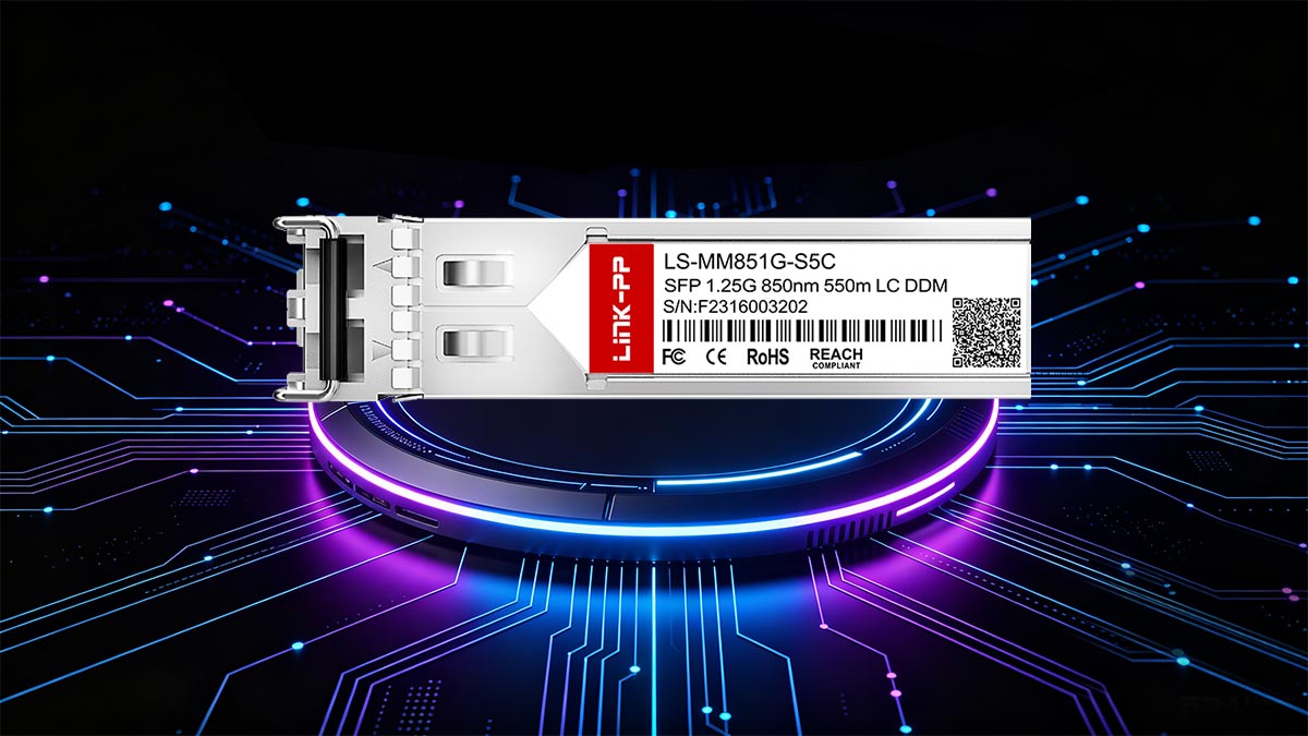
In legacy networking architectures, an SX LC connector serves as the standard physical interface for short-range Gigabit Ethernet connections over multimode fiber. It integrates the performance of the 1000BASE-SX optical standard with the compact design of a Duplex Lucent Connector (LC). This combination ensures reliable, high-density data transmission within local area networks (LANs) and data center backbones.
Defining 1000BASE-SX Optical Standards
The 1000BASE-SX standard is an IEEE 802.3z specification designed for data transmission over multimode fiber optics at gigabit speeds. It operates at a short wavelength, typically around 850nm, utilizing low-cost optical transmitters.
This standard is highly optimized for short-distance applications, such as connecting horizontal cross-connects within a building. It provides a budget-friendly alternative to long-wavelength single-mode systems while maintaining excellent signal integrity.
The Role of the LC Duplex Interface
The Lucent Connector (LC) duplex interface plays a critical role by providing a standardized, small-form-factor connection for separate transmit (TX) and receive (RX) channels. Its push-pull latching mechanism ensures a secure physical connection that resists accidental disconnection from cable tension.
By bundling two fiber strands into a single compact housing, the LC duplex layout doubles the port density on patch panels compared to older styles. This footprint optimization is crucial for maximizing space in crowded legacy network racks.
How SX LC Assemblies Power Multimode Links
An SX LC assembly consists of a duplex patch cord terminated with LC connectors, specially engineered to couple efficiently with multimode fiber cores. It ensures precise alignment between the transceiver's light source and the internal glass core of the fiber cable.
By minimizing optical loss at the connection point, these assemblies allow 850nm light pulses to travel smoothly across the link. This efficient energy transfer is what keeps short-range, high-bandwidth communication stable over legacy infrastructure.
Evolution from Legacy SC to Modern LC Physical Layers
The transition from legacy Subscriber Connectors (SC) to modern LC physical layers marked a major milestone in network scaling. The older SC style utilized a large 2.5mm ceramic ferrule, making its physical footprint twice the size of a standard LC connector.
Adopting the smaller LC connector, which features a compact 1.25mm ferrule, allowed network administrators to instantly double their port density without altering the underlying fiber. This evolution significantly improved airflow and rack space management in high-density data environments.
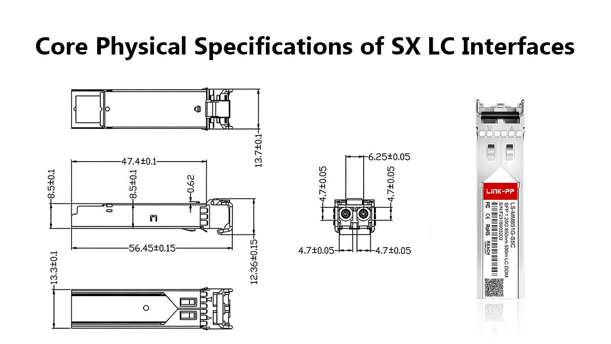
🍁 Core Physical Specifications of SX LC Interfaces
The mechanical integrity and optical performance of an SX LC interface rely entirely on strict physical manufacturing standards. These core specifications dictate how the connector aligns, couples, and retains its physical contact to prevent signal degradation. Adhering to these tight tolerances ensures optimal light transmission and hardware durability across legacy network environments.
Ferrule Material and End-Face Geometry (PC vs. UPC)
The internal construction of an SX LC connector centers around a high-precision ceramic zirconia ferrule that aligns the delicate fiber strands. To maximize light transmission, the glass end-face is polished into a specific geometry to control back-reflection, known as return loss.
The following table highlights the key structural and performance differences between the two primary polishing types found in these assemblies:
| Specification |
Physical Contact (PC) |
Ultra Physical Contact (UPC) |
| End-Face Profile |
Curved / Spherical |
Extensively Polished / Spherical |
| Typical Return Loss |
≥ 40dB |
≥ 50dB |
| Typical Insertion Loss |
﹤0.3dB |
﹤0.3dB (often slightly lower) |
| Surface Finish Quality |
Standard Polish |
Super-Fine Polish |
While PC polish is highly common in legacy multimode setups, UPC finish is typically reserved for single-mode applications requiring higher return loss. In such cases, the improved back-reflection performance (≥ 50dB) helps reduce optical noise and ensures cleaner data streams — though for standard 850 nm multimode links, the benefit of UPC over PC is negligible.
Mechanical Retention and Insertion Loss Tolerances
An SX LC connector uses a reliable push-pull latching system that provides an audible click when fully engaged in a bulkhead adapter. This mechanical retention mechanism is engineered to withstand external cable pull forces, preventing accidental micro-disconnects.
In terms of optical performance, the insertion loss tolerance for a high-quality SX LC joint is typically capped at 0.3dB or lower. Keeping insertion loss tightly controlled ensures that the total optical power budget of the 1G network is not prematurely depleted by poor mechanical connections.
Pitch and Form Factor Dimensions of Duplex LC
The physical layout of a duplex SX LC connector is governed by a strict Small Form Factor (SFF) design standard. It features a center-to-center fiber spacing, or pitch, of exactly 6.25mm within its dual-port housing.
This precise spacing matches the internal receiver and transmitter ports found on standard 1G SFP optical transceivers. By maintaining these exact miniature dimensions, the duplex layout allows network switches to offer high port density in a very restricted faceplate area.
Dust Protection and Keying Mechanisms for Safe Coupling
To preserve optical clarity, SX LC assemblies include integrated dust caps that shield the vulnerable 1.25mm ceramic ferrules when uncoupled. Because 850nm light is highly susceptible to scattering from microscopic debris, these caps are vital during storage and installation.
Additionally, the outer housing utilizes a molded keying mechanism that forces the connector to slide into the adapter in only one orientation. This molded guide prevents installation errors and protects the internal fiber faces from grinding against each other during coupling.
🍁 Fiber Compatibility Profiles for SX LC Deployments
Deploying SX LC hardware requires a clear understanding of the underlying multimode fiber infrastructure. Because the 1000BASE-SX standard relies on specific core sizes to guide light pulses, compatibility directly influences signal strength and reach. Matching the connector to the correct fiber profile prevents severe signal degradation and ensures stable gigabit performance.
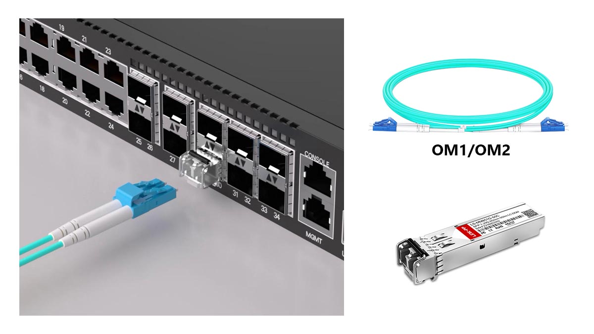
Interfacing with OM1 (62.5/125µm) Legacy Core Fiber
Connecting SX LC hardware to legacy OM1 fiber involves working with a relatively large 62.5-micron glass core. This wide core diameter was highly common in early enterprise networks because it made alignment with early light sources much easier.
However, the larger core allows light to bounce in many different paths, which quickly weakens the signal over longer distances. While SX LC assemblies easily couple with OM1, this combination is strictly limited to short-range building connections.
Coupling Optimization for OM2 (50/125µm) Infrastructure
OM2 fiber introduces a narrower 50-micron core, which provides a more streamlined path for light transmission. When an SX LC connector interfaces with OM2 infrastructure, the alignment must be highly precise to avoid light spilling into the cladding.
Optimizing this physical coupling significantly reduces signal loss at the connection point. This enables the 850nm optical signal to travel more efficiently, offering better overall bandwidth than older OM1 systems.
Modal Dispersion and Bandwidth Limits at 850nm
Modal dispersion is the primary physical constraint when running an SX LC network at an 850nm wavelength. Because light pulses travel down multimode fiber in multiple paths, the light rays arrive at the receiving end at slightly different times, causing the signal to blur.
At 850nm, this blurring effect puts a strict cap on the network's maximum bandwidth. As data speeds try to push past 1G, modal dispersion becomes too severe, making legacy SX LC setups unsuitable for high-speed upgrades without replacing the fiber.
Maximum Reach Constraints Across Varying Core Diameters
The maximum distance an SX LC link can achieve depends directly on the core diameter of the fiber being used. When deployed over 62.5µm OM1 fiber, the maximum reliable reach for a 1G link is technically constrained to approximately 275m.
Upgrading to 50µm OM2 fiber extends this maximum distance up to roughly 550m due to improved light guidance. Exceeding these standardized distance limits introduces high bit-error rates, causing intermittent network drops and packet loss.
🍁 Optical Transceiver Matching for SX LC Ports
Achieving a stable fiber optic link requires perfect compatibility between the physical SX LC connector and the active optical transceiver. The transceiver acts as the engine, converting electrical data into light pulses and vice versa through dedicated transmission ports. Proper matching ensures that optical power levels remain within safe operating boundaries, preventing signal degradation or hardware damage.
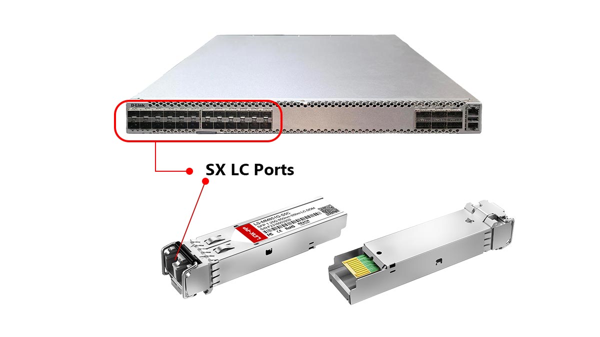
SFP 1G SX Modules and LC Interfacing
SFP 1G SX modules are the standard active hardware used to drive legacy multimode networks. These hot-swappable transceivers feature a built-in receptacle explicitly designed to receive the dual-prong SX LC patch cord.
When the SX LC connector plugs into the SFP module, it locks securely into place to align the internal glass fibers with the transceiver's optical components. This precise interface minimizes initial signal loss and ensures steady, uninterrupted gigabit performance.
Decoupling Transceiver TX/RX Power Budgets
An optical link's power budget is calculated by separating the transmitter's outbound power (TX) from the receiver's inbound sensitivity (RX). For an SX LC system to function correctly, the total light lost across the cable and connectors must not exceed this allocated budget.
If the fiber path introduces too much resistance, the light arriving at the RX port will be too faint to read. Decoupling and measuring these individual values allows network technicians to verify that the SX LC hardware is operating within safe, predictable margins.
Understanding 850nm VCSEL Laser Source Restrictions
Legacy 1000BASE-SX transceivers typically utilize Vertical-Cavity Surface-Emitting Laser (VCSEL) technology operating at a strict 850nm wavelength. While VCSELs are highly cost-effective and reliable, their light output is tightly restricted to multimode fiber cores.
Attempting to couple an 850nm VCSEL through an SX LC patch cord into single-mode fiber will cause extreme light scattering and immediate link failure. Understanding this hardware restriction is vital when planning or maintaining physical layer cross-connects.
Receiver Sensitivity and Saturation Risk Analysis
Receiver sensitivity defines the minimum amount of light an SFP module needs to accurately decode a data stream. Conversely, receiver saturation occurs when the incoming optical signal is too strong, blinding the sensitive optical components.
Because SX LC setups operate over short distances, using an overpowered light source can easily flood the receiver. Conducting a saturation risk analysis ensures that the light levels are balanced, preventing packet corruption or permanent hardware burnout.
🍁 Troubleshooting Common SX LC Connection Failures
Even well-engineered SX LC networks can experience performance drops due to physical layer disruptions. Identifying and resolving these connection issues promptly is vital to preventing unexpected network downtime. By applying structured troubleshooting techniques, administrators can easily isolate optical or mechanical faults within their legacy infrastructure.
Diagnosing High Insertion Loss from Contamination
Microscopic contamination is the single most common cause of high insertion loss in short-range multimode links. Because the 850nm light wave relies on clean physical contact, even tiny particles can block the optical path. Technicians can diagnose and resolve this issue by executing the following steps:
- Inspect with a Fiber Scope: Use a specialized inspection camera to visually check the 1.25mm ceramic ferrule for dust, skin oils, or pulling lubricants.
- Execute a Wet-to-Dry Clean: Clean the SX LC end-face using an optical-grade click cleaner or lint-free wipes and specialized solvent, then dry it completely before re-testing.
Never plug a dirty connector into an SFP transceiver, as this can permanently bake dust onto the sensitive optical lens. Consistently inspecting and cleaning every connection ensures that the optical link operates well within its planned power budget.
Identifying TX/RX Polarity Crossovers (A-to-B vs. A-to-A)
Polarity issues occur when the transmitting laser on one end of a link is mistakenly routed to the transmitting laser on the opposite end. For an SX LC duplex assembly to function, the transmit (TX) fiber must connect directly to the receive (RX) port on the other side. This proper routing is known as an A-to-B crossover connection.
If you observe an active port showing no link light while power levels seem normal, a straight-through (A-to-A) polarity error might be the cause. Resolving this requires physically unclipping the dual LC housing and flipping the internal fiber positions on one end. Correcting this configuration establishes a proper loop, allowing the transceivers to communicate immediately.
Resolving Mechanical Misalignment and Loose Latch Engagement
Physical wear or low-quality plastic clips can prevent an SX LC connector from locking securely into an SFP module or bulkhead adapter. Mechanical misalignment happens when the connector sits slightly askew, keeping the fiber cores from touching perfectly. This gap causes light to scatter, resulting in high attenuation and intermittent link drops.
- Listen for the Click: Always push the duplex connector into the port until you hear a distinct, physical clicking sound that indicates tight latch engagement.
- Inspect the Latch Mechanism: Check the plastic clip for fractures, warping, or loss of tension that might allow the cable to back out under its own weight.
Replacing worn-out patch cords or securing loose adapters eliminates small air gaps between the ferrules. This mechanical stability ensures the tight physical contact required for low-loss, 1G data transmission.
Microbends and Macrobends Near the Patch Panel Bulkhead
Physical cable stress can severely warp the internal glass core, causing light to leak out of the fiber cladding. This stress manifests as either macrobends, which are sharp curves visible to the human eye, or microbends, which are localized microscopic pressures. Both issues commonly occur inside crowded patch panels right behind the bulkhead adapter.
To eliminate bend-induced failures, technicians should always maintain the manufacturer-specified minimum bend radius for multimode fiber. Avoid pulling patch cables tightly around sharp metal rack corners or stuffing excess lengths carelessly into management trays. Using proper routing hangers relieves physical tension, allowing the 850nm light to travel smoothly through the core.
🍁 Strategic Procurement Criteria for SX LC Hardware
Procuring SX LC components requires a strategic approach that goes beyond simply finding the lowest price. Because these components bridge legacy infrastructure and modern switches, buyers must evaluate multi-vendor compatibility, supply chain reliability, and strict standard compliance. Selecting the right hardware ensures long-term network stability and minimizes the total cost of ownership.

Multi-Vendor Compatibility and EEPROM Coding Validation
When sourcing transceivers and cables for an SX LC network, verifying multi-vendor compatibility is critical. Many major networking brands use proprietary software locks that reject third-party hardware. Therefore, procurement teams must ensure that the optical components are properly coded to match the specific host switches.
EEPROM coding validation is the process used to confirm that the transceiver's internal memory chip contains the correct vendor handshake data. Buying components from suppliers who rigorously test and program these EEPROM chips prevents frustrating port-recognition errors. This validation guarantees a true plug-and-play experience across different hardware platforms.
Supply Chain Resilience and Strategic Inventory Auditing
Maintaining a resilient supply chain is vital for keeping legacy SX LC infrastructure operational. Because many manufacturers are shifting focus to high-speed optics, finding high-quality legacy parts on short notice can become difficult. Establishing relationships with multiple trusted suppliers prevents project delays caused by sudden component shortages.
Regularly performing a strategic inventory audit helps organizations track their consumption rates and predict future needs. Keeping a safe buffer stock of SX LC patch cords and adapters ensures immediate replacement parts are available during emergency network outages. This proactive approach eliminates long lead times and protects the business from unexpected downtime.
Testing for Compliance with RoHS and IEEE 802.3z Standards
Procured SX LC hardware must strictly adhere to international engineering and environmental standards. Buyers should always demand documentation proving compliance with the IEEE 802.3z standard, which governs the parameters of 1000BASE-SX gigabit optical transceivers. This compliance ensures that the physical dimensions and optical outputs match industry expectations perfectly.
Additionally, environmental certifications like RoHS (Restriction of Hazardous Substances) are essential for modern corporate compliance. RoHS certification guarantees that the plastic and metal components of the SX LC housing are free from dangerous materials like lead or cadmium. Purchasing certified hardware ensures safe handling, environmental responsibility, and seamless regulatory approval.
Evaluating Supplier Warranty and Technical Support Channels
A supplier's long-term value is often defined by the strength of their warranty and customer service. High-quality SX LC SFP transceivers should come with comprehensive warranties that cover material defects and premature optical degradation. Opting for a multi-year warranty provides buyers with peace of mind regarding product durability.
Furthermore, accessible technical support channels are indispensable when integration issues arise in complex legacy networks. An ideal supplier provides direct access to knowledgeable network engineers who can assist with troubleshooting or transceiver selection. Having this professional support readily available dramatically speeds up problem resolution during critical deployments.
🍁 Migration Strategies from SX LC to High-Speed Infrastructure
As data demands grow, transitioning from legacy SX LC systems to high-speed networks becomes an operational necessity. Upgrading infrastructure requires a balanced strategy that maximizes the value of current assets while integrating faster optical technologies. By planning clear migration paths, organizations can scale their bandwidth seamlessly without forcing massive, expensive structural overhauls.
Scaling from 1G SX to 10G SR and 25G SR Networks
Upgrading from a 1G SX LC setup to 10G or 25G Short Range (SR) networks represents a massive leap forward in data throughput. Fortunately, these higher-speed standards continue to utilize the same 850nm wavelength logic and compact LC duplex physical connector footprint. This structural similarity means you can often swap out the older 1G SFP transceivers for newer SFP+ or SFP28 modules directly inside your existing switches.
However, moving to higher speeds severely reduces the maximum distance the signal can travel over older glass profiles. While a 1G SX link can cover hundreds of meters, a 10G or 25G SR link will experience high signal degradation over long runs of legacy fiber. Network managers must map out their distance requirements carefully before initiating a widespread hardware swap.
Reusing Existing Multimode Fiber Plant via Mode Conditioning Patch Cables
Completely replacing underground or in-wall legacy fiber cables is incredibly expensive and labor-intensive. To avoid this, networks can reuse their existing OM1 or OM2 multimode plant by deploying specialized Mode Conditioning Patch (MCP) cables. These unique cables bridge the gap between newer single-mode laser transmitters and older, wide-core multimode infrastructure.
An MCP cable works by launching a single-mode laser pulse slightly off-center into the multimode core, preventing the light from splitting into too many conflicting paths. This precise calibration drastically minimizes modal dispersion and extends the lifespan of your physical cable plant. Utilizing this method allows organizations to safely run higher-speed protocols over their old SX LC backbone.
Upgrading Bulkhead Adapters and High-Density Patch Panels
Scaling a network to support high-speed connections inevitably requires a denser physical layout inside server racks. Older patch panels designed for simple 1G networks often feature wide spacing that wastes valuable real estate. Upgrading to ultra-high-density patch panels allows you to pack significantly more LC connections into the same amount of rack space.
During this physical upgrade, it is critical to replace older bulkhead adapters with high-performance, ceramic-sleeve LC couplers. These modern adapters offer tighter alignment tolerances, which are essential for keeping insertion loss low at 10G and 25G speeds. This simple hardware refresh ensures your physical layer can handle the strict performance requirements of modern, high-speed data transmission.
🍁 Conclusion: Mastering Interoperability and Sourcing for SX LC Hardware
Mastering the physical and optical intricacies of SX LC hardware is the key to maintaining a highly stable and efficient legacy multimode network. By understanding the mechanical tolerances, transceiver compatibility, and core configurations of these systems, network administrators can successfully prevent signal drops and streamline troubleshooting. Ultimately, managing your physical layer infrastructure with a proactive strategy protects your historical investments while preparing a smooth roadmap for future high-speed upgrades.
When it comes to sourcing dependable components that ensure flawless multi-vendor compatibility and strict compliance standards, choosing a trusted hardware partner makes all the difference. Explore a premium selection of high-performance 1G SX SFP modules and advanced optical solutions by visiting the LINK-PP Official Store. Equip your infrastructure with the reliable engineering your business needs to stay connected without interruption.


