
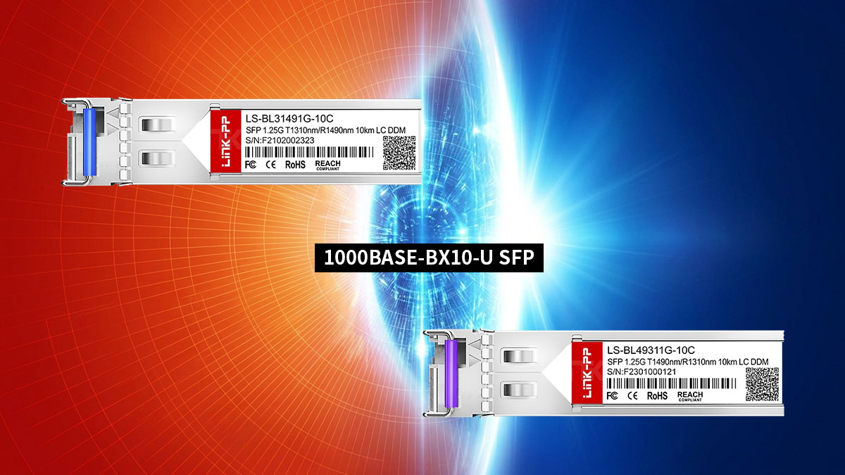
In modern fiber-optic networking, maximizing cable plant efficiency is paramount. The 1000BASE-BX10-U SFP transceiver represents a cornerstone of this effort, utilizing Bidirectional (BiDi) technology to enable gigabit Ethernet transport over a single strand of single-mode fiber. Unlike dual-strand optics transceivers that require separate fibers for transmitting and receiving, the upstream "U" variant relies on a master-slave architecture to optimize infrastructure. However, deploying these components successfully requires a strict adherence to specific pairing mechanics and wavelength symmetry.
To establish a functional optical link, a 1000BASE-BX10-U module cannot operate in isolation or connect to an identical upstream unit. It depends entirely on a precise spectral marriage, transmitting at 1310nm and receiving at 1490nm, which mandates a direct interconnection with its downstream counterpart. This article breaks down the core physics, wavelength allocation logic, and precise troubleshooting steps required to seamlessly pair and optimize your upstream BiDi network infrastructure.
📘 Core Pairing Mechanics of the 1000BASE-BX10-U SFP
Establishing a stable connection with a 1000BASE-BX10-U SFP relies on a precise set of physical and operational rules. Unlike traditional transceivers, this module is engineered to operate within a strictly coordinated pairing ecosystem over a single fiber strand. Understanding these fundamental mechanics is the first step toward preventing deployment errors and ensuring seamless data transmission.
The Fundamental Definition of an Upstream BiDi Module
The 1000BASE-BX10-U is a Bidirectional (BiDi) SFP transceiver designed for upstream communications. The "U" in its nomenclature explicitly designates it as the upstream unit, which typically resides at the central office or core switch side of a network.
This module is purpose-built to aggregate traffic from the network edge. It serves as the primary anchor point of a single-strand optical circuit, initiating the specific frequency alignment required for bidirectional data flow.
Single-Strand Bidirectional Signaling Principles
Traditional optical networks use two separate fiber strands to handle traffic, where one strand is dedicated to transmitting (TX) and the other to receiving (RX). BiDi technology changes this dynamic by allowing both transmission and reception to occur simultaneously over just one single-mode fiber strand.
To keep these two data paths from colliding, the system uses two distinct wavelengths of light traveling in opposite directions. This approach effectively doubles the capacity of existing fiber infrastructure by eliminating the need for a second physical fiber patch.
Why a 1000BASE-BX10-U Cannot Form a Link with Another Upstream Unit
A common installation error is attempting to connect a 1000BASE-BX10-U directly to another 1000BASE-BX10-U. Because every upstream module transmits at a fixed wavelength of 1310nm and listens at 1490nm, two identical units would end up speaking on the same frequency and listening on the other.
As a result, both transceivers would blindly transmit light into paths where the opposing receiver is not listening. Without a complementary frequency swap on the other end, the optical link will remain completely down.
Understanding the Master-Slave Hierarchy in BiDi Networks
BiDi networks operate on a strict master-slave structural hierarchy to guarantee order over the shared single fiber strand. In this topology, the 1000BASE-BX10-U upstream module functions as the master device, dictating the baseline timing and frequency structure for the circuit.
The downstream unit acts as the slave device, matching the clocking and adhering to the reciprocal wavelength profile. This hardcoded hierarchy eliminates signaling conflicts and ensures that data flows smoothly without packet collisions or timing synchronization issues.
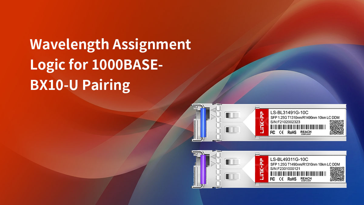
📘 Wavelength Assignment Logic for 1000BASE-BX10-U Pairing
The successful operation of a 1000BASE-BX10-U link depends entirely on structured wavelength coordination across a single fiber strand. By dividing the optical spectrum into distinct channels for transmission and reception, the system ensures that data streams flowing in opposite directions never interfere with one another. Achieving this absolute isolation requires a precise combination of hardcoded wavelength assignments and internal optical filtration technologies.
The 1310nm Transmit (TX) and 1490nm Receive (RX) Standard
The 1000BASE-BX10-U transceiver is engineered to adhere to a strict industry standard for upstream wavelength allocation. It utilizes a 1310nm laser to transmit outbound data traffic from the central office or core network switch out into the field. Conversely, its internal receiver component is specifically calibrated to listen for incoming optical signals at a wavelength of 1490nm.
This specific wavelength split is optimized for standard single-mode fiber infrastructure over short-to-medium ranges. Operating at these frequencies allows the optical signals to travel efficiently while minimizing signal degradation over distances up to 10km.
Matching the Optical Spectrum with Downstream Components
For an upstream module to function, it must be paired with a device that mirrors its exact spectral properties on the opposite end of the fiber. While the upstream unit sends data at 1310nm, the remote device must be actively listening at that exact same frequency. At the same time, the remote device must send its outbound data at 1490nm to match the upstream unit's receiver.
This perfect overlap creates an interlocking optical circuit where the transmission peak of one module aligns with the reception window of the other. Without this exact spectral matching, the light sent from the upstream module would simply be ignored or blocked by the remote receiver.
How Internal WDM Filters Separate TX and RX Paths
Inside the compact housing of every 1000BASE-BX10-U sits a specialized component known as a Wavelength Division Multiplexing (WDM) filter. This microscopic passive optical filter acts as a highly specialized traffic cop for the incoming and outgoing light waves. It allows the outbound 1310nm laser light to exit onto the fiber strand while simultaneously redirecting incoming 1490nm light toward the photodiode receiver.
By utilizing this internal prism-like filter, the transceiver can seamlessly manage two independent optical paths inside a single physical port connector. This internal component eliminates the need for external multiplexing hardware, keeping the physical deployment clean and efficient.
Spectral Isolation and Preventing Near-End Crosstalk (NEXT)
Maintaining high spectral isolation is critical because the outbound laser is located physically close to the highly sensitive inbound receiver inside the SFP. If the outbound 1310nm light leaks into the local receiver path, it creates severe Near-End Crosstalk (NEXT) that blinds the module. The internal WDM filter prevents this by providing deep optical isolation between the two internal channels.
This robust isolation ensures that the strong local transmit signal does not drown out the weak, attenuated signal arriving from miles away. Proper spectral isolation guarantees clear, error-free communication even when the laser is operating at maximum output power.
📘 Identifying the Correct Downstream Counterpart for 1000BASE-BX10-U
Deploying a 1000BASE-BX10-U SFP requires selecting the correct complementary hardware on the opposite end of the optical link. Because BiDi technology relies on exact optical symmetry, using an incompatible module will result in a total link failure. Successful deployment hinges entirely on mastering industry standards, naming conventions, and cross-branding rules to pinpoint the precise downstream counterpart for your upstream transceiver.
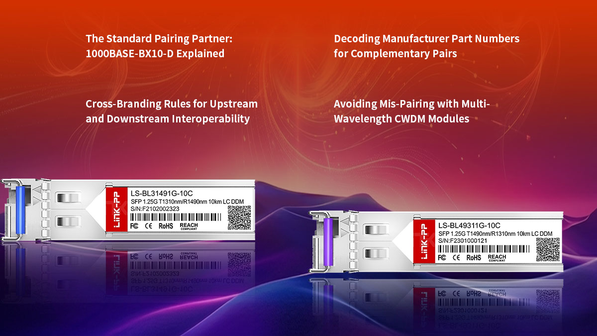
The Standard Pairing Partner: 1000BASE-BX10-D Explained
The official, industry-standard pairing partner for the 1000BASE-BX10-U is the 1000BASE-BX10-D SFP transceiver. The "D" suffix explicitly stands for "Downstream," signifying its role at the remote terminal or client side of the network. It mirrors the upstream unit by shifting its internal optical spectrum to transmit and receive on reciprocal channels.
To visualize how these two components interface across a single fiber strand, the following table details their complementary specifications:
| Feature / Specification |
1000BASE-BX10-U (Upstream) |
1000BASE-BX10-D (Downstream) |
| Network Role |
Central Office / Core Switch |
Remote Site / Network Edge |
| Transmit Wavelength (TX) |
1310nm |
1490nm |
| Receive Wavelength (RX) |
1490nm |
1310nm |
| Link Distance (Max) |
10km |
10km |
| Fiber Media Type |
Single-Mode Fiber (SMF) |
Single-Mode Fiber (SMF) |
Decoding Manufacturer Part Numbers for Complementary Pairs
Most network equipment manufacturers use explicit labeling and suffix conventions to help engineers identify matching optics. You will frequently find part numbers explicitly appended with -U and -D, or clearly displaying the dual-wavelength specification on the module label.
Carefully auditing these identifier codes during the staging phase prevents frustrating deployment delays. Ensuring your field kits contain an equal distribution of matching upstream and downstream optics is vital for a successful rollout.
Cross-Branding Rules for Upstream and Downstream Interoperability
Multi-vendor interoperability is fully supported across the 1000BASE-BX10 optical standard, meaning you can mix different transceiver brands on a single link. For example, a 1000BASE-BX10-U module plugged into a Cisco switch at the core can successfully establish a link with a 1000BASE-BX10-D module plugged into an HP switch at the remote site. The optical signal traveling through the fiber is standardized, so the transceivers will communicate seamlessly regardless of who manufactured them.
The key to multi-vendor setups is host compatibility, not the optical connection between the modules. Network switches often require transceivers to be programmed with specific vendor EEPROM code to be recognized and enabled. Therefore, you must ensure that the upstream SFP is compatible with your core switch, and the downstream SFP is compatible with your remote switch, even if the two SFPs come from different third-party suppliers like LINK-PP.
Avoiding Mis-Pairing with Multi-Wavelength CWDM Modules
It is critical not to confuse standard 1000BASE-BX10-U optics with multi-wavelength Coarse Wavelength Division Multiplexing (CWDM) modules. CWDM platforms also leverage single-mode fiber but utilize a much wider grid of 18 distinct channels ranging from 1270nm to 1610nm.
Attempting to link a BX10-U with a CWDM module — even one transmitting close to 1490nm — will fail due to mismatched passband tolerances. Always verify that your remote site optic is a true, single-channel BiDi partner rather than a multiplexed enterprise alternative.
📘 Optical Power Budgeting for Balanced 1000BASE-BX10-U Links
Maintaining a healthy optical power budget is essential for ensuring link stability and preventing packet loss over a single-strand connection. Because light behaves differently at various frequencies, engineers must calculate total signal attenuation from the upstream end to the downstream destination. Properly balancing these transmission variables ensures that the receiver on either end is neither starved of signal nor overwhelmed by excess optical power.
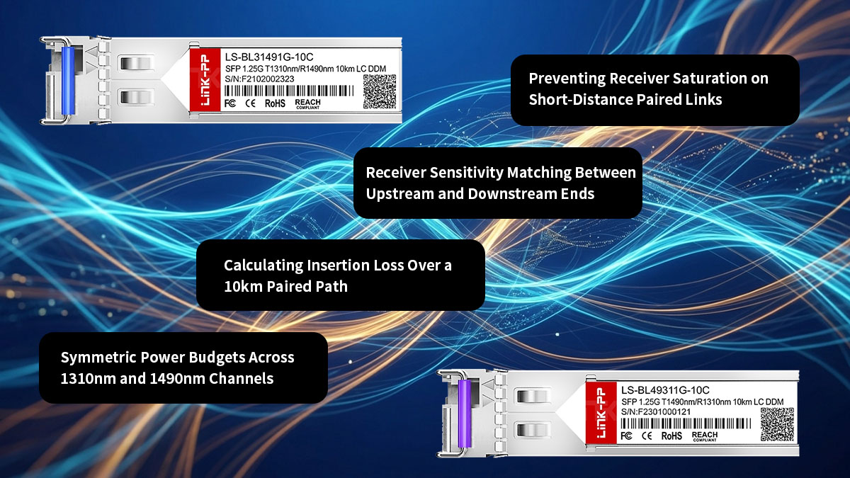
Symmetric Power Budgets Across 1310nm and 1490nm Channels
Designing a stable single-strand link requires calculating the power budget for two distinct optical channels simultaneously. Even though both signals share the exact same physical glass, light traveling at 1310nm experience different attenuation characteristics than light at 1490nm. A truly balanced deployment accounts for these differences to maintain symmetric performance.
Engineers typically focus on a few primary variables to ensure both channels operate within safe parameters:
- Fiber Attenuation Bias: Standard single-mode fiber naturally exhibits higher loss at 1310nm (around 0.35dB/km) compared to 1490nm (around 0.25dB/km). This means the upstream transmit signal will degrade slightly faster over distance than the downstream return signal.
- Transmitter Output Alignment: To compensate for the unequal fiber attenuation, quality 1000BASE-BX10-U modules are calibrated with slightly different baseline launch powers. This factory adjustment ensures that the optical energy arriving at both receivers remains relatively equal.
Calculating Insertion Loss Over a 10km Paired Path
To verify if a paired 1000BASE-BX10-U link will function reliably over its maximum 10km range, you must calculate total insertion loss. This calculation involves adding up the predictable loss of the fiber run itself along with the localized loss introduced by physical infrastructure. The total sum must never exceed the maximum power budget specified by the transceiver manufacturer.
When calculating this budget for a 10km run, the total insertion loss is typically broken down into three main buckets:
- Fiber Run Loss: A standard 10km single-mode fiber span contributes a baseline loss of roughly 3.5dB for the 1310nm upstream channel and about 2.5dB for the 1490nm downstream channel.
- Connector and Adapter Loss: Every physical connection point, such as a patch panel coupling or equipment bulkhead, introduces an average insertion loss of 0.3dB to 0.5dB per mated pair.
- Fusion and Mechanical Splices: Permanent fiber splices along the outdoor plant add approximately 0.1dB of attenuation per splice point, which must be factored into the overall link budget.
Receiver Sensitivity Matching Between Upstream and Downstream Ends
Receiver sensitivity defines the minimum amount of optical power a 1000BASE-BX10-U SFP needs to accurately decode a data stream. If the light arriving from the downstream partner falls below this threshold, the link will drop, or suffer from severe bit error rates. Therefore, checking that the incoming light sits comfortably above the sensitivity floor is critical.
A balanced system ensures that the incoming signal power leaves a healthy cushion for unexpected environmental changes. Network designers generally include a 3dB safety margin to account for fiber aging, macrobends, or future emergency patch splices without risking a total network outage.
Preventing Receiver Saturation on Short-Distance Paired Links
While insufficient optical power causes link drops, excessive optical power can be equally damaging to a 1000BASE-BX10-U module. When deploying these transceivers over short distances, such as inside a single server room or across a campus loop, the laser signal has little room to naturally degrade.
If unattenuated light hits the remote photodiode, it can cause receiver saturation, leading to immediate link performance issues:
- Bit Error Rate Spikes: An overwhelmed receiver cannot distinguish between the high and low states of the incoming light waves. This optical blinding causes massive data corruption, resulting in CRC errors and dropped packets.
- Permanent Hardware Damage: Prolonged exposure to optical power levels that exceed the maximum receive threshold can permanently burn out the sensitive photodiode component, ruining the SFP module completely.
- Using Fixed Attenuators: If a short-run diagnostic test or deployment shows that the received power is too high, installing a 5dB or 10dB fixed inline LC optical attenuator will safely lower the power back into the optimal operating window.
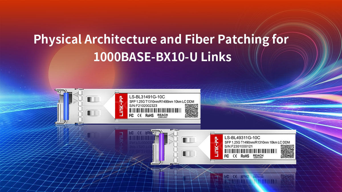
📘Physical Architecture and Fiber Patching for 1000BASE-BX10-U Links
Setting up the physical layer for a 1000BASE-BX10-U link requires a shift from standard dual-strand fiber habits. Since transmission and reception occur on a single strand of glass, the choice of connectors, patch cables, and routing methods must match this specialized architecture. Getting the physical infrastructure right prevents signal degradation and ensures a highly reliable installation.
Simplex LC/UPC Connector Requirements for Upstream Ports
Unlike traditional dual-strand SFP modules that use a duplex LC connector, the 1000BASE-BX10-U features a single physical port. This setup requires a Simplex LC patch cable to handle both transmit and receive paths through one connector boot.
The optical standard also dictates a blue-coded UPC (Ultra Physical Contact) ferrule polish for standard deployments. Using a green APC (Angled Physical Contact) connector by mistake will cause an air gap inside the port, leading to severe signal loss.
Single-Mode Fiber (SMF) Continuity from Upstream to Downstream
The 1000BASE-BX10-U optic is built exclusively for single-mode fiber (SMF) infrastructure, typically using standard OS2 cabling. Attempting to run this module over multi-mode fiber will fail due to high modal dispersion and massive optical attenuation.
Maintaining strict physical continuity means verifying that no multi-mode patch cords are accidentally mixed into the path. The entire glass path from the upstream core switch to the downstream client device must remain pure single-mode glass.
Patch Panel Routing for Single-Strand BiDi Circuits
Routing single-strand BiDi circuits through enterprise patch panels requires careful labeling and organized management. Technicians used to working with duplex pairs can easily misroute or split single-strand connections during cross-connect additions.
To prevent these configuration mistakes, each single-strand circuit should occupy a clearly designated port on the panel. Clear labeling that identifies the circuit as an active BiDi link helps ensure future technicians do not accidentally break the path trying to find a matching duplex pair.
Impact of Fiber Splices and Connectors on Paired Signal Integrity
Every physical connection point along the fiber path impacts overall signal integrity. Dust particles, fingerprint oils, or poor fusion splices introduce localized insertion loss and back-reflections that degrade performance.
Because the 1000BASE-BX10-U shares its single strand with a return signal, it is highly sensitive to reflections caused by dirty connectors. Implementing a strict "inspect, clean, and test" routine before plugging into the SFP prevents intermittent packet loss and keeps the link highly stable.
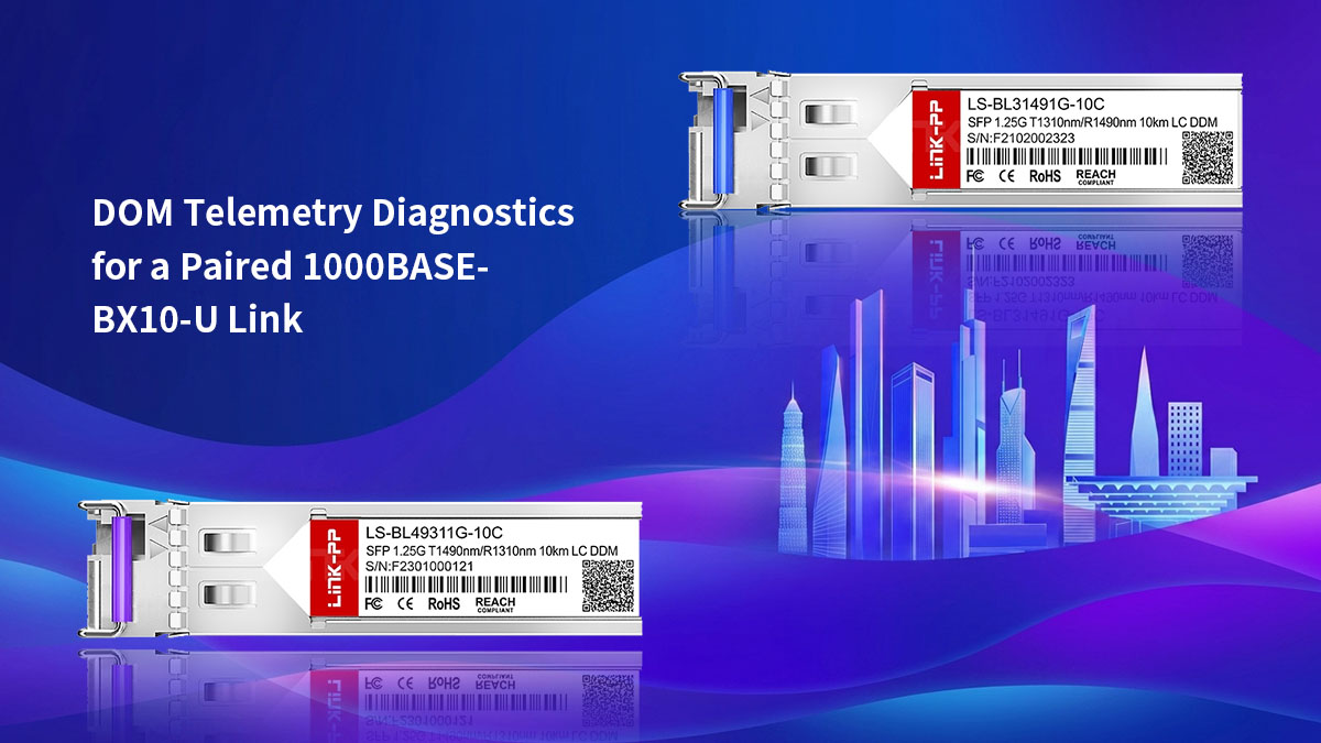
📘 DOM Telemetry Diagnostics for a Paired 1000BASE-BX10-U Link
Digital Optical Monitoring (DOM) provides network administrators with real-time telemetry data to evaluate the health of an active fiber connection. By leveraging the command-line interface (CLI) of a host switch, engineers can monitor critical metrics such as optical power levels, internal temperatures, and operational currents. Utilizing these integrated diagnostics allows for proactive link maintenance and quick resolution of performance anomalies across the single-strand network.
Reading Real-Time TX Power of the Upstream Module via CLI
Checking the transmit (TX) power of the 1000BASE-BX10-U module through the switch CLI is the first step in assessing link health. This telemetry value indicates the precise amount of optical energy the internal 1310nm laser is pushing into the fiber infrastructure. Evaluating this metric helps confirm whether the transmitter itself is functioning within normal manufacturer parameters.
When auditing the upstream transmitter output via your switch console, look for these specific indicators:
- Normal Output Thresholds: A healthy 1000BASE-BX10-U module typically launches light at a power level between -9dBm and 0dBm. If the reading falls squarely within this range, the local laser is performing adequately.
- Low TX Power Warning: A telemetry readout that drops below -9dBm often points to an aging internal laser component. This drop in output power reduces the overall link budget and can lead to intermittent connectivity.
Validating Received Optical Power (RX) From the Downstream Partner
Monitoring the received optical power (RX) on the 1000BASE-BX10-U is critical because it tells you exactly how much 1490nm light is reaching the upstream photodiode. This value directly reflects the optical attenuation introduced by the fiber plant, patch panels, and outdoor splices. Evaluating the RX power helps you determine if the incoming signal has degraded too much over the single strand.
A healthy downstream connection should display a steady RX telemetry reading that meets two primary criteria:
- Above the Sensitivity Floor: The incoming signal must remain stronger than the receiver sensitivity threshold, which usually sits around -23dBm. Any reading lower than this will cause immediate packet loss and link drops.
- Below the Saturation Maximum: The received power should not exceed the maximum threshold of -1dBm. Keeping the signal below this limit ensures the photodiode isn't blinded by excessive light over short fiber runs.
Correlating Temperature and Bias Current Across the Paired Link
Analyzing internal temperature alongside laser bias current provides deep insight into the structural and operational stability of the transceiver. As an SFP module ages or operates in harsh environments, it must work harder to maintain its target optical output power. Tracking these two metrics together allows technicians to catch hardware fatigue before a total link failure occurs.
Anomalies in these diagnostic readings generally manifest through specific telemetry behaviors:
- Elevated Temperature Readings: While standard optical transceivers are rated to operate safely up to 70°C, sustained operation near this thermal ceiling indicates poor ventilation or a failing internal chip.
- Spiking Laser Bias Current: The bias current represents the driving electrical force behind the laser diode. If the DOM data shows a steady increase in milliamperes (mA) while the TX power stays flat, the laser is actively degrading and requires replacement.
Troubleshooting Threshold Alarms in BiDi Transceiver Pairs
Modern network operating systems automatically flag operational anomalies by triggering specific DOM threshold alarms. These system logs are categorized into high or low "warnings" and "alarms," depending on how far a metric strays from normal operating limits. Correctly interpreting these software flags speeds up the troubleshooting process for single-strand BiDi links.
When a 1000BASE-BX10-U link begins to degrade, administrators will typically encounter one of two primary alarm types:
- Rx Power Low Alarm: This message indicates that the incoming signal has dropped below a safe operating level. This issue is usually caused by physical fiber problems, such as a severe macrobend, a dirty connector, or a broken splice along the path.
- Tx Fault Alarm: A Tx Fault indicates a hardware-level failure inside the upstream transmitter itself. When this error triggers, the module usually shuts down its laser entirely to prevent sending corrupted optical signals down the line.
📘 Troubleshooting Mismatched and Failed 1000BASE-BX10-U Pairs
When a single-strand BiDi link fails to establish or experiences performance drops, a structured troubleshooting approach is required to pinpoint the root cause. Because bidirectional communication relies on strict wavelength pairing and precise physical connectivity, a single mismatch can bring down the entire circuit. The following outlines the most common failure modes and provides clear, actionable steps to restore your upstream optical network.
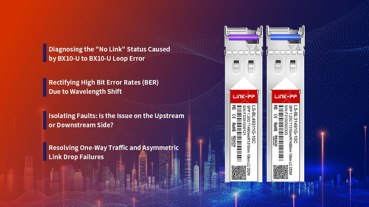
Diagnosing the "No Link" Status Caused by BX10-U to BX10-U Loop Error
If the switch port remains in a persistent "No Link" or "Down" state, the most common culprit is an accidental upstream-to-upstream configuration. Connecting a 1000BASE-BX10-U directly to another BX10-U means both ends are transmitting at 1310nm and listening at 1490nm.
Because neither receiver is getting the correct wavelength, the host switches will report a total lack of optical signaling. To diagnose this, check the physical labels on both ends of the fiber or use the switch CLI to verify that one side is properly equipped with a downstream "D" variant.
Rectifying High Bit Error Rates (BER) Due to Wavelength Shift
High Bit Error Rates (BER) often present as intermittent packet drops, CRC errors, or sluggish network performance. This issue can occur when a transceiver experiences an internal wavelength shift, which happens when an aging laser drifts away from its exact 1310nm target.
When the transmitted wavelength drifts, the internal WDM filters on the receiving end can no longer isolate the signal cleanly. Replacing the unstable upstream transceiver is typically the most efficient way to eliminate these errors and restore data integrity.
Isolating Faults: Is the Issue on the Upstream or Downstream Side?
When a link drops, determining which side of the fiber run is failing can be challenging. A great way to isolate the issue is to review the DOM telemetry data from both the upstream and downstream switches simultaneously.
If the 1000BASE-BX10-U shows normal TX power but the remote unit shows extremely low RX power, the issue is likely a dirty connector or a fiber break along the path. However, if the upstream module reports a TX fault or zero output power, you can confidently isolate the problem to the local hardware itself.
Resolving One-Way Traffic and Asymmetric Link Drop Failures
One-way traffic occurs when data flows smoothly in one direction but drops completely in the other. In a 1000BASE-BX10-U ecosystem, this asymmetry is typically caused by localized damage or dirt on only one of the internal sub-components.
For instance, a speck of dust sitting on the 1490nm receiver path will blind the upstream unit while leaving the 1310nm transmitter free to send data cleanly. Cleaning the simplex LC connector with an industry-standard fiber click-cleaner or swapping out the impaired module will resolve this lopsided failure mode.
📘 Final Takeaways for Optimizing Your 1000BASE-BX10-U Upstream Network Links
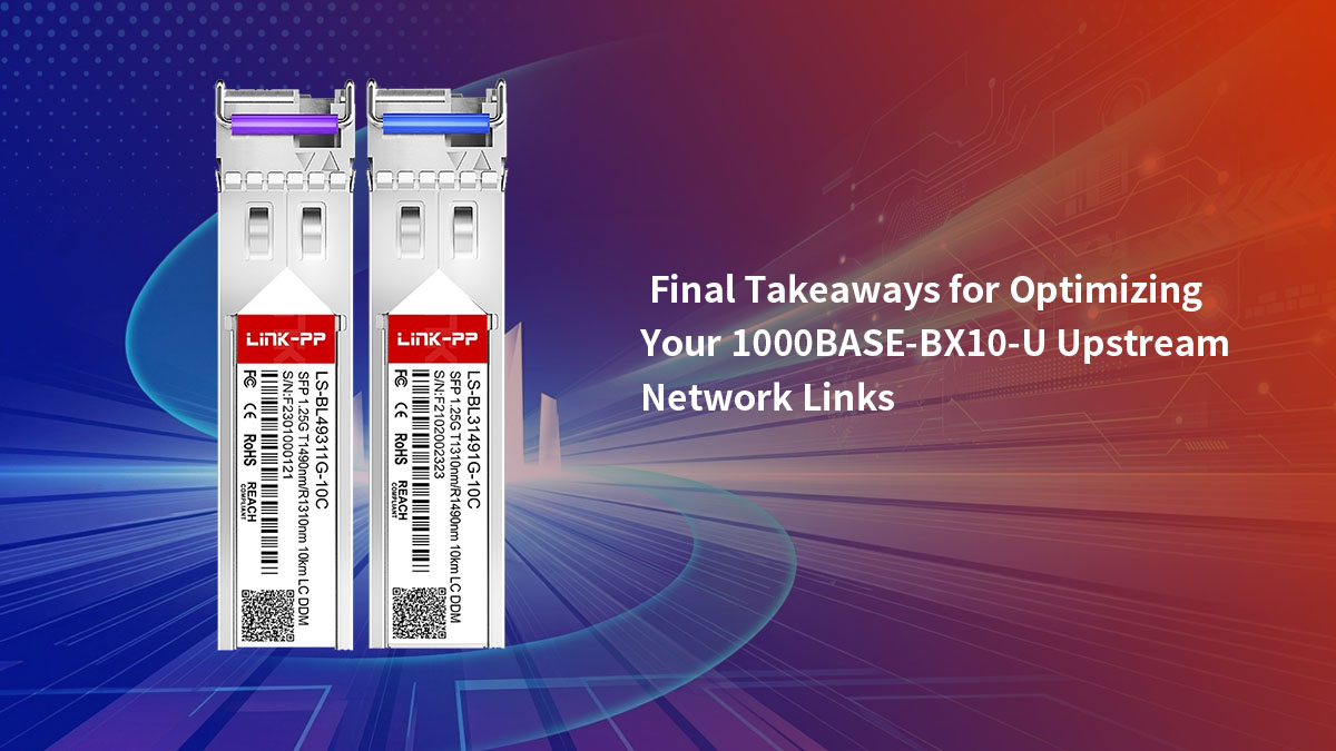
Optimizing a 1000BASE-BX10-U upstream link comes down to respecting the rules of BiDi pairing mechanics and maintaining clean physical habits. Always ensure your upstream "U" modules are perfectly matched with downstream "D" counterparts to avoid the dreaded identical-unit loop error. By keeping a close eye on your DOM telemetry and calculating precise insertion loss budgets, you can guarantee stable, carrier-grade performance across your single-strand fiber network.
Ready to upgrade your infrastructure with reliable, highly compatible BiDi SFP optics transceivers? Explore a wide selection of high-performance transceivers tailored to your specific hardware needs by visiting the LINK-PP Official Store. Their field-tested modules ensure perfect wavelength alignment, robust spectral isolation, and seamless multi-vendor interoperability for all your upstream deployments.


