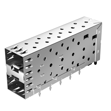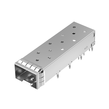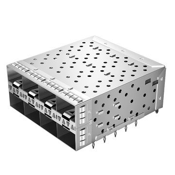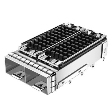
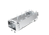
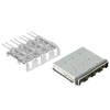

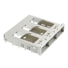

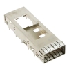


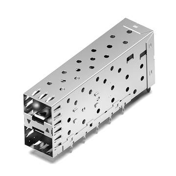



Replacing an SFP cage in an existing network hardware design may seem straightforward, especially when an alternative component has similar dimensions and mounting features. However, even small differences in mechanical tolerances, EMI spring geometry, or PCB mounting details can create problems during assembly and operation.
The biggest risks are not limited to whether a replacement cage fits the PCB. A mismatched press-fit pin pattern can damage plated through-holes, an incorrectly positioned EMI spring can compromise chassis shielding, and insufficient internal clearance can prevent an SFP transceiver from being inserted or removed properly. These issues can lead to EMC retesting, PCB rework, production delays, and costs far exceeding the price difference between two cage components.
This guide presents a practical seven-point form-fit-function (FFF) checklist for evaluating a drop-in SFP cage replacement:
-
Mechanical dimensions and mounting geometry.
-
PCB footprint and press-fit pin compatibility.
-
SFP module insertion, retention, and extraction.
-
EMI spring geometry and EMC shielding.
-
Grounding and electrical interface integration.
-
Thermal management, materials, and environmental compatibility.
-
Prototype testing and production qualification.
By following these checks before approving an alternative component, hardware engineers can reduce replacement risks, protect existing PCB designs, and establish whether a proposed SFP cage is genuinely suitable for production.
Verify the Overall SFP Cage Dimensions and Mechanical Envelope
A drop-in SFP cage replacement must match the original component's critical mechanical dimensions, mounting orientation, port configuration, and reference positions. Similar external dimensions alone do not establish mechanical interchangeability because even small differences can affect PCB positioning, front-panel alignment, and module clearance.
The first step is to obtain the original and replacement engineering drawings and compare their mechanical envelopes before proceeding to physical testing.
Compare the Critical External Dimensions
The external dimensions of an SFP cage determine whether it can occupy the same mechanical space as the original component. Engineers should compare all critical dimensions rather than relying on catalog descriptions or product photographs.
The main dimensions to verify include:
-
Overall length: Confirm the distance from the front mating interface to the rear mounting area.
-
Overall width: Check the cage width and the spacing between adjacent ports.
-
Overall height: Verify compatibility with the original board-to-panel clearance.
-
Front opening dimensions: Compare the width, height, and geometry of the module entry.
-
Cage wall thickness: Check whether differences affect structural rigidity or internal clearance.
-
Mounting features: Compare locating tabs, retaining structures, and other mechanical reference points.
Dimensional tolerances are equally important. Two SFP cages may have identical nominal dimensions but different allowable deviations, potentially creating alignment problems when combined with PCB, chassis, and front-panel tolerances.
For a reliable comparison, use the same datum references and coordinate system for both engineering drawings. If 3D CAD models are available, overlay them to identify dimensional differences that may not be obvious in a two-dimensional drawing.
Confirm Port Configuration and Mounting Orientation
Port configuration and mounting orientation must also match the original hardware design. An SFP cage with the correct overall width may still be incompatible if its port arrangement or mounting geometry differs.
Check the following characteristics:
-
Single-port 1x1 versus multi-port 1xN configurations.
-
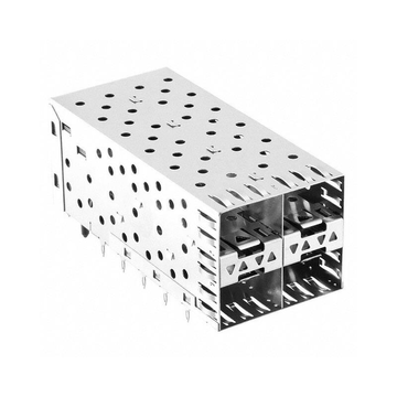
Single-row versus stacked 2xN cage arrangements.
-
Right-angle mounting orientation.
-
Port pitch and center-to-center spacing.
-
Front-panel opening alignment.
-
Individual cage versus ganged cage assembly.
-
Position of light pipes, if included in the original design.
For example, replacing a single-port SFP cage with a multi-port assembly is not a direct substitution, even if some individual port dimensions appear similar. The surrounding mechanical structure and PCB mounting requirements may be different.
The replacement should preserve the original port arrangement and front-panel interface unless the hardware design is intentionally modified.
Check the Mechanical Tolerance Stack-Up
Mechanical tolerance stack-up determines whether all components remain properly aligned when their individual manufacturing tolerances are combined. It is particularly important in compact network equipment, where the cage, PCB, chassis, front panel, and host connector must work together.
A practical tolerance review should include:
-
Cage positioning relative to the PCB datum.
-
PCB thickness and mounting tolerances.
-
Distance between the cage opening and front-panel cutout.
-
Clearance from neighboring components and structural supports.
-
Alignment between the cage and host connector.
-
Worst-case dimensional deviations across the complete assembly.
Do not evaluate the replacement cage in isolation. A component that fits a nominal CAD model may still interfere with the chassis or front panel at worst-case manufacturing tolerances.
Once the mechanical envelope is verified, the next step is to confirm that the replacement can be installed on the existing PCB without changing its mounting footprint.
Verify the PCB Footprint and Press-Fit Pin Compatibility
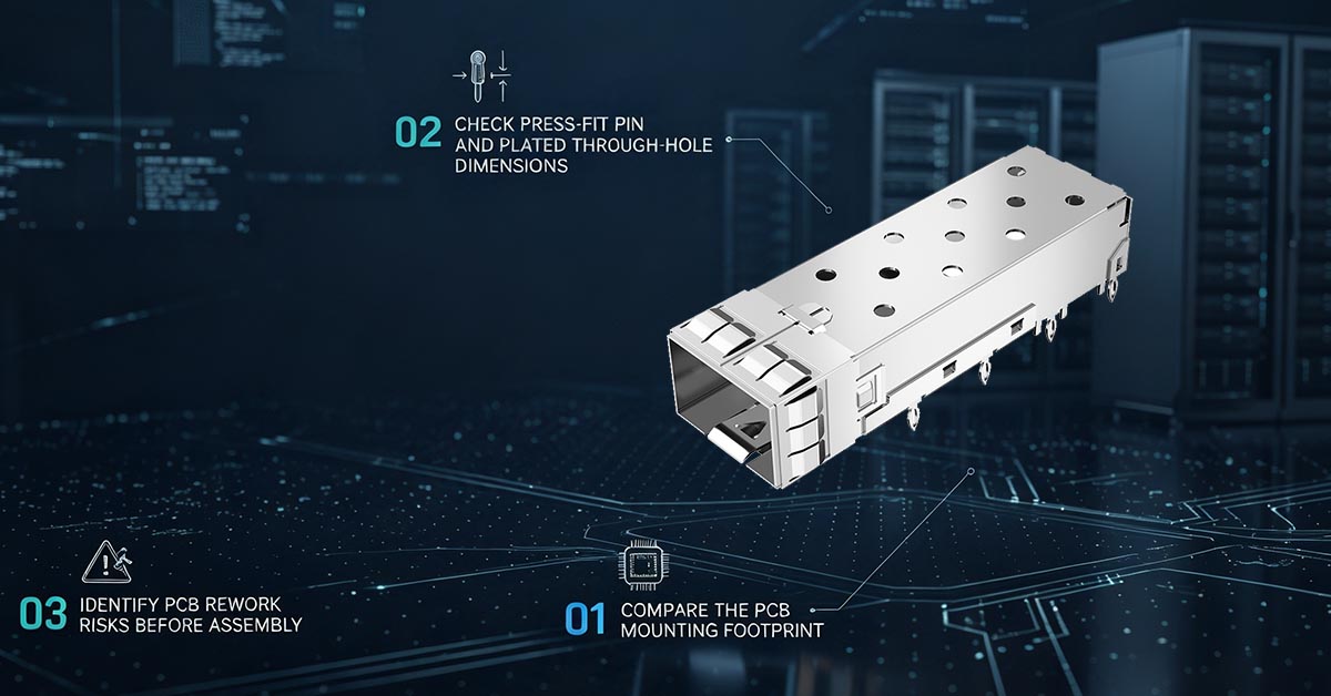
PCB footprint compatibility is one of the most critical requirements for a drop-in SFP cage replacement. Every mounting pin must align with its corresponding PCB hole, and the press-fit termination geometry must be compatible with the specified plated through-hole dimensions.
A replacement cage that looks identical externally can still fail during PCB assembly if its pin positions, tail dimensions, or termination method differ from the original.
Compare the PCB Mounting Footprint
The PCB footprint defines the mounting-hole arrangement and mechanical positioning of the SFP cage. Engineers should compare the original and replacement footprint drawings using consistent datum references.
Important footprint characteristics include:
-
Number of mounting pins and their arrangement.
-
X-Y coordinates of each pin.
-
Pin-to-pin spacing and positional tolerances.
-
Hole locations relative to the cage centerline.
-
PCB edge clearance.
-
Grounding pad and via locations.
-
Component and trace keep-out areas.
Pay particular attention to the relationship between the mounting holes and the SFP host connector. A small positional deviation can cause the cage to sit incorrectly, creating interference during module insertion.
PCB keep-out information also deserves careful review. The replacement must not occupy areas reserved for neighboring components, signal traces, or mechanical structures.
Where available, compare the original and alternative PCB footprints directly in the PCB layout software. This makes it easier to identify shifted holes, different pin arrangements, and potential conflicts before manufacturing.
Check Press-Fit Pin and Plated Through-Hole Dimensions
A press-fit SFP cage uses compliant pins to establish mechanical retention and electrical contact through plated through-holes. Its pin geometry must therefore match the PCB hole design and the manufacturer's specified assembly requirements.
The following parameters should be checked:
-
Pin width and thickness: Determine whether the compliant section matches the intended hole dimensions.
-
Compliant-zone geometry: Verify the shape and dimensions of the press-fit section.
-
Tail length: Confirm that the pins provide sufficient penetration without interfering with the opposite PCB surface or nearby structures.
-
Finished PTH diameter: Check the actual plated-hole dimensions rather than only the nominal drill size.
-
Hole-position tolerance: Confirm that the mounting holes fall within the allowable positional range.
-
PCB thickness: Verify compatibility with the specified press-fit pin design.
The relationship between pin geometry and hole diameter is especially important. An undersized hole can increase insertion force and potentially damage the PCB barrel, while an oversized hole may reduce mechanical retention and electrical contact reliability.
The replacement manufacturer's recommended hole dimensions and insertion-force limits should take precedence over assumptions based on the original cage.
Also distinguish between press-fit and solder-through-hole termination. These mounting methods are not automatically interchangeable, even when the external cage geometry is similar.
Identify PCB Rework Risks Before Assembly
PCB rework is one of the most expensive consequences of approving an incompatible SFP cage. Problems that appear minor during drawing review can become serious once the replacement reaches the assembly line.
Typical warning signs include:
-
Press-fit pins that do not enter the PCB holes smoothly.
-
Pins that require excessive insertion force.
-
Mounting holes that are oversized or undersized.
-
Misaligned pins that prevent complete cage seating.
-
Damaged plating or cracked PCB barrels.
-
Lifted pads or mechanical damage around mounting holes.
-
A replacement that requires additional drilling or PCB layout changes.
Before approving the alternative, verify that the cage can be installed using the existing PCB footprint and an appropriate assembly process.
If a footprint modification is required, the component should no longer be treated as a straightforward drop-in replacement. The associated PCB redesign, manufacturing, and qualification costs must be included in the engineering assessment.
Verify SFP Module Insertion, Retention, and Extraction
A mechanically compatible SFP cage must accept the intended transceiver modules smoothly, retain them securely, and allow reliable extraction without excessive force or mechanical interference. Matching the cage's external dimensions does not guarantee that its internal geometry is compatible with the module.
The most effective verification method is to test the replacement with representative modules rather than relying exclusively on engineering drawings.
Check the Module Entry and Internal Clearance
The front opening and internal cavity determine how an SFP module enters and sits inside the cage. Any dimensional difference in these areas can affect module alignment and mating.
Check the following features:
-
Module entry width and height.
-
Internal cage clearance.
-
Guide surfaces and alignment features.
-
Clearance around the transceiver housing.
-
Space for the module latch mechanism.
-
Alignment with the host connector.
-
Potential interference with internal cage structures.
The module should enter the cage without catching on the front opening or rubbing excessively against the internal walls.
Pay particular attention to the relationship between the cage and the host connector. Even if the module can enter the cage, incorrect cage positioning may prevent the module's electrical interface from reaching the intended mating position.
Validate Latch Engagement and Extraction
Proper module retention is essential for reliable operation in network switches, routers, and other pluggable optical equipment. The replacement cage must preserve the mechanical conditions needed for the module latch to engage and release correctly.
Evaluate:
-
Bail-latch or pull-tab clearance.
-
Latch engagement and locking position.
-
Module retention after insertion.
-
Accessibility of the release mechanism.
-
Extraction force and movement.
-
Clearance around the front-panel bezel.
-
Potential interference with neighboring ports.
A cage that accepts a module but prevents the latch from engaging is not mechanically compatible. Similarly, a module that can be inserted but cannot be extracted easily may create maintenance problems in the field.
Repeated insertion and extraction tests can reveal friction, deformation, and retention issues that may not appear during a single assembly attempt.
Test with Representative SFP Modules
Testing with actual pluggable modules provides a more realistic assessment than checking the cage dimensions alone. The test samples should reflect the module types and mechanical variations expected in the target equipment.
Depending on the application, include:
-
Standard SFP optical transceivers.
-
SFP+ modules.
-
SFP28 modules.
-
Different transceiver housing designs within the supported form factor.
For each representative module, verify:
-
Smooth insertion and complete seating.
-
Correct connector mating.
-
Reliable latch engagement.
-
Stable retention during normal handling.
-
Smooth extraction without abnormal resistance.
-
Clearance between adjacent modules and ports.
For multi-port assemblies, test neighboring ports simultaneously. A module may fit correctly in an isolated cage but become difficult to access when adjacent modules or cables are installed.
These tests help distinguish basic dimensional compatibility from practical mechanical compatibility in the complete network hardware assembly.
Verify EMI Spring Geometry and EMC Shielding Performance
EMI spring geometry is a critical factor in SFP cage replacement because the cage must maintain reliable conductive contact with the equipment front panel or chassis to support electromagnetic shielding. A replacement with different spring positions, contact angles, or compression characteristics can compromise shielding continuity even when its external dimensions appear identical.
This is particularly important in network equipment where multiple pluggable I/O openings are located close together.
Compare EMI Spring Design and Contact Positions
EMI spring fingers provide compliant electrical contact between the metal cage and the surrounding conductive enclosure. Their geometry determines how the cage interfaces with the front-panel bezel.
Compare the following characteristics:
-
Number and arrangement of EMI spring fingers.
-
Spring length and width.
-
Finger height and contact angle.
-
Spring spacing and contact positions.
-
Material and plating.
-
Spring flexibility and mechanical recovery.
-
Internal versus external EMI spring arrangements.
The contact locations should match the original shielding interface. Differences in spring geometry may cause some fingers to lose contact with the bezel or create uneven contact pressure.
Also check whether the replacement cage uses the same type of spring arrangement as the original. A cage with internal EMI springs is not necessarily interchangeable with one using external spring fingers.
Check Cage-to-Chassis and Front-Panel Contact
The cage must establish a consistent conductive interface with the chassis or front-panel opening. This connection helps maintain shielding continuity around the pluggable I/O port.
During mechanical inspection, verify:
-
Alignment between the cage and front-panel cutout.
-
Spring compression after installation.
-
Contact pressure around the cage perimeter.
-
Conductive contact with the intended chassis surfaces.
-
Front-panel material and surface finish.
-
Potential gaps caused by dimensional differences.
Insufficient spring compression may result in intermittent electrical contact. Excessive compression can also be problematic because it may deform the spring fingers or make assembly difficult.
The actual enclosure configuration matters. A replacement cage should be evaluated with the intended front panel and chassis rather than only on a standalone PCB fixture.
Validate EMC Performance After Replacement
EMI spring similarity does not establish EMC equivalence. Electromagnetic compatibility must be validated in the complete hardware configuration because shielding performance depends on the cage, PCB grounding, chassis, front panel, cable arrangement, and surrounding components.
A practical EMC verification process includes:
-
Inspecting the conductive interface between cage and chassis.
-
Measuring electrical continuity at relevant contact points.
-
Checking for gaps or discontinuities around the port opening.
-
Comparing replacement and original shielding structures.
-
Conducting EMC pre-compliance testing.
-
Repeating applicable formal EMC tests when required by the product qualification plan.
The testing should follow the relevant product requirements and applicable EMC standards. Do not assume that passing a continuity test automatically means the replacement will pass radiated or conducted emissions testing.
This distinction is important: electrical continuity confirms a conductive path, while EMC testing evaluates the actual electromagnetic behavior of the assembled equipment.
Verify Grounding, Electrical Interface, and PCB Integration
A replacement SFP cage must preserve the intended grounding and shielding arrangement without interfering with the host connector, PCB layout, or high-speed signal paths. Although the cage is primarily a mechanical and shielding component, its integration directly affects the electrical environment of the SFP interface.
The cage should therefore be evaluated as part of the complete PCB assembly rather than as an isolated metal enclosure.
Inspect Cage Grounding and Conductive Contact
The metal cage typically contributes to the grounding and shielding structure around the pluggable module interface. Its grounding features must be compatible with the original PCB and chassis design.
Check the following:
-
Grounding pin positions and contact geometry.
-
Grounding pads and vias around the cage footprint.
-
Electrical continuity between the cage and designated grounding structures.
-
Conductive plating and surface finish.
-
Cage-to-PCB and cage-to-chassis contact.
-
Differences in grounding arrangements between the original and replacement designs.
Pay special attention to the PCB drawing. Some cage designs specify dedicated chassis-ground pads and vias around the mounting area, which should not be treated as ordinary signal connections.
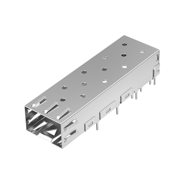
For example, the LINK-PP LP11AC02000 engineering drawing identifies chassis-ground pads and vias and specifies separate PCB keep-out regions. This information should be reviewed alongside the mounting-hole layout when evaluating the model for an existing PCB design.
The grounding arrangement must remain consistent with the system's electrical and EMC design requirements.
Check Compatibility with the SFP Host Connector
The SFP cage and host connector perform different functions. The cage provides the mechanical enclosure and shielding structure, while the host connector establishes the electrical connection to the transceiver.
A cage replacement must not disturb the host connector's position or mating geometry.
Verify:
-
Relative positioning between the cage and host connector.
-
Connector locating features and alignment.
-
Module insertion depth.
-
Paddle-card mating position.
-
Clearance between the cage and connector body.
-
Clearance around connector solder joints.
-
Potential interference with nearby PCB components.
The replacement cage should allow the module to mate with the host connector at the intended position without excessive mechanical loading.
Do not assume that two cages are interchangeable simply because they accommodate the same SFP form factor. Differences in mounting geometry may shift the module position relative to the host connector.
Evaluate PCB Layout and High-Speed Signal Integrity Risks
The cage itself is not the high-speed signal connector, but its mounting and grounding structures can influence the surrounding PCB implementation.
When a replacement requires any footprint or layout modification, evaluate the electrical consequences before releasing the design.
Important considerations include:
-
Ground-plane continuity around the SFP interface.
-
Return-current paths near high-speed differential pairs.
-
PCB copper keep-out areas.
-
Grounding via locations.
-
Clearance from differential signal routing.
-
Potential changes to impedance-controlled structures.
-
Effects of modified mounting-hole positions on nearby routing.
For an unchanged PCB footprint, the primary concern is whether the replacement preserves the original mechanical and grounding relationships. If the PCB layout must change, the signal integrity impact should be assessed according to the interface's data-rate and channel requirements.
The objective is to maintain the original electrical interface rather than introduce unnecessary PCB changes during a mechanical component substitution.
Verify Thermal Management, Material, and Environmental Compatibility
A suitable SFP cage replacement must also satisfy the thermal, material, and environmental requirements of the target equipment. This becomes particularly important when the original cage includes an integrated heat sink or when the system operates under elevated ambient temperatures.
Mechanical compatibility alone cannot establish whether a replacement is suitable for long-term operation.
Compare Heat Sink and Thermal Management Features
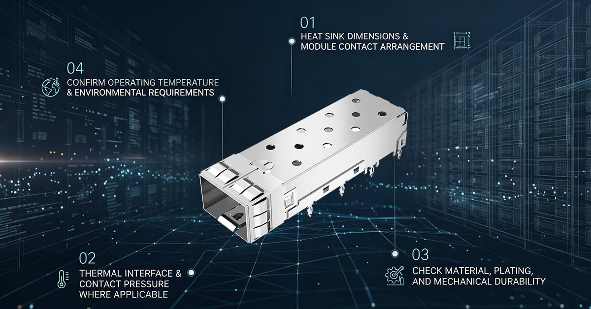
Some SFP cage assemblies include integrated heat sinks that help transfer heat from the transceiver housing toward the surrounding airflow.
If the original cage uses an integrated heat sink, verify:
-
Heat sink dimensions and fin geometry.
-
Contact position relative to the module housing.
-
Thermal contact pressure, where applicable.
-
Clearance for airflow.
-
Interference with neighboring components.
-
Compatibility with the original thermal design.
A standard SFP cage should not automatically replace a heat-sink-equipped assembly. Removing or changing the thermal contact structure may affect module operating temperatures.
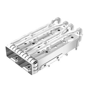
For example, LINK-PP's LP11AC02060 is an SFP 1x1 cage assembly featuring an integrated heat sink, press-fit termination, and EMI spring fingers. Its design illustrates why thermal configuration must be included in the replacement comparison rather than treating all SFP cages as mechanically equivalent.
Where thermal contact is part of the original design, validate the replacement under representative module power and airflow conditions.
Check Material, Plating, and Mechanical Durability
The cage material and surface finish influence conductivity, corrosion resistance, mechanical stability, and long-term contact performance.
Compare:
-
Base metal and material specification.
-
Nickel or other specified conductive plating.
-
Surface finish and coating thickness, where specified.
-
Corrosion resistance.
-
EMI spring material and elasticity.
-
Mechanical fatigue resistance.
-
Applicable RoHS and material compliance documentation.
Material differences can affect more than appearance. A different plating system may change contact resistance or corrosion behavior, while different spring materials may affect long-term contact pressure.
For EMI spring fingers, repeated compression and release should not cause permanent deformation that compromises contact with the front panel.
The replacement should meet the same application-specific material and reliability requirements as the original component.
Confirm Operating Temperature and Environmental Requirements
Operating temperature is an important qualification parameter for SFP cage assemblies used in industrial networking, telecom equipment, and data-center infrastructure.
Review:
-
Specified operating temperature range.
-
Thermal expansion and mechanical stability.
-
Spring performance across the temperature range.
-
Corrosion and oxidation resistance.
-
Humidity and environmental exposure requirements.
-
Compatibility with the operating conditions of the complete equipment.
The following table illustrates how selected LINK-PP SFP cage models differ in mounting and thermal configuration. These are product-level reference specifications, not proof of universal interchangeability.
|
LINK-PP Model |
Port Configuration |
PCB Termination |
EMI Feature |
Integrated Heat Sink |
Operating Temperature |
|---|---|---|---|---|---|
|
LP11AC02000 |
SFP 1x1 |
Press-fit |
EMI spring fingers |
No |
-55°C to +85°C |
|
LP11AC02060 |
SFP 1x1 |
Press-fit |
EMI spring fingers |
Yes |
-55°C to +85°C |
|
LP11ACS2000S |
SFP 1x1 |
Through-hole solder |
EMI spring fingers |
No |
-40°C to +85°C |
The differences demonstrate why engineers should compare the complete specification rather than selecting a cage based on its port configuration alone. In particular, press-fit and solder termination are different PCB mounting methods, and an integrated heat sink introduces additional mechanical and thermal requirements.
Validate the Replacement with a Production-Level Form-Fit-Function Test
A drop-in SFP cage replacement should only be approved after dimensional comparison, prototype assembly, module mating, grounding inspection, and applicable EMC and reliability testing. Engineering drawings establish preliminary compatibility, but physical validation determines whether the replacement works in the intended hardware environment.
A documented qualification process also makes it easier to identify deviations before they become production problems.

Build a 7-Point Original-versus-Replacement Comparison Matrix
The first step is to consolidate the engineering findings into one comparison matrix. This allows hardware engineers to identify missing specifications and unresolved compatibility risks before prototype assembly.
Use the following checklist as a qualification reference.
|
Verification Point |
Critical Evidence |
Acceptance Criteria |
|---|---|---|
|
1. Mechanical dimensions |
2D drawings and 3D CAD models |
Critical dimensions and tolerances are compatible |
|
2. PCB footprint |
Footprint drawings and PTH specifications |
All mounting pins align with PCB holes |
|
3. Module mating |
Insertion, retention, and extraction tests |
Smooth mating and reliable retention |
|
4. EMI shielding |
Spring geometry and EMC test reports |
Shielding meets system requirements |
|
5. Grounding and interface |
Continuity and connector alignment tests |
Intended grounding and mating relationships maintained |
|
6. Thermal and materials |
Material specifications and thermal test reports |
Application requirements satisfied |
|
7. Production validation |
Assembly and reliability test records |
Repeatable and qualified manufacturing process |
Each item should have documented evidence rather than a simple visual approval. If a critical specification is unavailable, the corresponding verification point should remain open until sufficient information or test results are obtained.
This matrix can also serve as part of an engineering change review when replacing an existing component with an alternative manufacturer model.
Perform Prototype Assembly and First-Article Inspection
Prototype assembly provides an opportunity to detect mechanical and manufacturing problems before mass production.
A practical first-article inspection should include:
-
Obtain the original and replacement 2D engineering drawings.
-
Compare 3D CAD models and critical reference dimensions.
-
Verify PCB mounting-hole coordinates.
-
Inspect press-fit pin alignment and geometry.
-
Confirm correct cage seating and positioning.
-
Check front-panel and chassis alignment.
-
Test representative SFP module insertion and extraction.
-
Inspect the PCB for damaged plating, pads, or barrels.
-
Record assembly force and any abnormal mechanical resistance.
For press-fit designs, use the manufacturer's specified insertion tooling and process limits. Do not force a misaligned cage into the PCB simply to complete the assembly test.
If the cage cannot be installed consistently without modifying the existing PCB, it should not be classified as a direct drop-in replacement.
Complete EMC, Thermal, and Reliability Qualification
After successful prototype assembly, the replacement should undergo system-level qualification according to the equipment's requirements.
The test plan should cover:
-
Electrical continuity at relevant grounding interfaces.
-
Cage-to-chassis contact and shielding integrity.
-
EMC pre-compliance and applicable formal testing.
-
Thermal performance with representative SFP modules.
-
Module retention and repeated insertion/extraction.
-
Mechanical stability under applicable environmental conditions.
-
Inspection of EMI spring deformation and contact consistency.
-
Comparison against the original cage's baseline performance.
EMC testing deserves particular attention. A replacement may pass dimensional inspection and still perform differently because of changes in spring compression, contact location, or chassis integration.
Similarly, thermal qualification should use representative modules and realistic airflow conditions rather than relying exclusively on the cage's standalone temperature rating.
The final acceptance criteria should be defined before testing begins so that the original and replacement components are evaluated consistently.
Understand When a Replacement Is Truly Drop-In Compatible
A genuine drop-in SFP cage replacement must satisfy all three elements of form-fit-function compatibility.
Form refers to whether the replacement preserves the required physical characteristics:
-
External dimensions and mechanical envelope.
-
Mounting orientation and port configuration.
-
PCB footprint and pin arrangement.
-
EMI spring and heat sink geometry, where applicable.
Fit determines whether the replacement integrates correctly with the existing hardware:
-
Correct alignment with PCB mounting holes.
-
Proper cage seating and front-panel positioning.
-
Sufficient clearance for the intended modules.
-
Reliable latch engagement and extraction.
-
Compatibility with the chassis and host connector.
Function confirms whether the replacement maintains the required operational performance:
-
EMI shielding and grounding continuity.
-
Thermal management performance.
-
Mechanical retention and durability.
-
Environmental compatibility.
-
System-level EMC and reliability requirements.
Passing only one or two of these categories is not sufficient. A cage may match the external dimensions but fail PCB assembly, or it may fit the board while compromising EMI shielding.
How LINK-PP SFP Cage Solutions Support Replacement Projects
At LINK-PP, we provide SFP cage solutions for network hardware development, component replacement, and PCB integration. Our product range includes different termination methods, port configurations, and EMI shielding arrangements to accommodate varying design requirements.
For engineers evaluating alternative SFP cages, several product characteristics are particularly relevant:
-
Press-fit mounting options: Selected models use compliant pins for through-hole PCB installation.
-
Solder termination options: Through-hole solder designs are available for PCB assemblies using conventional soldering processes.
-
EMI spring finger designs: Selected cages incorporate perimeter EMI spring fingers to support conductive contact with the equipment front panel.
-
Integrated heat sink options: Certain assemblies include heat sinks for applications requiring additional transceiver thermal management.
-
Different port configurations: The product range includes single-port and multi-port cage arrangements.
-
Engineering documentation: Product specifications and mechanical drawings help engineers compare dimensions, mounting features, and PCB footprints.
For example, three models illustrate different configurations within our SFP cage range:
-
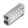
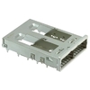
LP11AC02000: An SFP 1x1 cage with press-fit through-hole termination and EMI spring fingers.
-
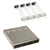
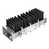
LP11AC02060: An SFP 1x1 press-fit cage with EMI spring fingers and an integrated heat sink.
-
LP11ACS2000S: An SFP 1x1 cage with through-hole solder termination and EMI spring fingers.
These models are not interchangeable by default. Their termination methods, dimensions, thermal features, and operating specifications must be checked against the original component and system requirements.
Engineers can review the LINK-PP SFP cage product range and obtain the relevant engineering drawings for a more detailed comparison.
For replacement projects, we recommend starting with the original part number and PCB footprint. This provides a clear basis for identifying a potentially suitable LINK-PP alternative and planning prototype evaluation.
Conclusion
A reliable drop-in SFP cage replacement must satisfy all three form-fit-function requirements: matching the original mechanical design, fitting the existing PCB and chassis, and maintaining the required electrical, shielding, and thermal performance. Matching external dimensions is only the starting point; PCB footprint differences, press-fit pin misalignment, and EMI spring variations can create expensive problems after assembly.
Before approving an alternative SFP cage, make sure these seven verification points are covered:
-
Mechanical dimensions: Confirm the cage envelope, port arrangement, and mounting geometry.
-
PCB compatibility: Verify pin positions, press-fit geometry, and plated through-hole dimensions.
-
Module fit: Test insertion, retention, latch engagement, and extraction.
-
EMC shielding: Compare EMI spring geometry, contact pressure, and chassis integration.
-
Grounding: Preserve the original grounding paths and host connector alignment.
-
Thermal and material requirements: Check heat sink configuration, plating, and operating temperature.
-
Production qualification: Complete prototype assembly, EMC testing, and reliability validation.
A few additional engineering checks before production can prevent PCB rework, EMC retesting, and manufacturing delays that may cost many times more than the price difference between the original and replacement cage.
At LINK-PP, we offer different SFP cage configurations to support hardware designers evaluating alternative components. If you are considering an SFP cage replacement, start by sharing the original part number, PCB footprint, or engineering drawing with our team. We can help identify a potentially suitable model and provide the relevant specifications for comparison.
Request an SFP cage sample for engineering evaluation before committing to production. You can also explore the LINK-PP Official Store for available models. Standard-stock items are covered by a 15-day no-reason return/exchange policy, and we cover return shipping costs for quality-related issues.