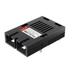
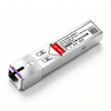
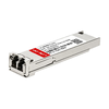
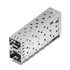
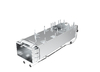
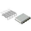

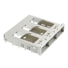

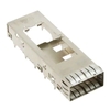
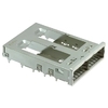
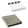
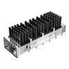


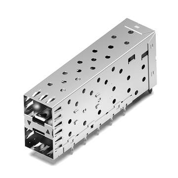



QSFP+ connectors play an important role in high-speed networking equipment, providing the electrical interface between pluggable transceiver modules and host circuit boards. They are widely used in 40G Ethernet switches, routers, servers, and data center hardware. As equipment manufacturers maintain existing platforms or develop new PCB designs, finding compatible connector alternatives becomes important for component sourcing and design continuity.
The TE Connectivity 1761987-9 is a 38-position QSFP+ receptacle connector featuring a right-angle, surface-mount design. For applications requiring an alternative, LINK-PP LP11D000003 is listed as a compatible cross-reference model. Both connectors share key configuration characteristics, although their operating temperature ratings differ and detailed footprint verification remains necessary.
This article provides a technical comparison and replacement reference covering:
-
TE 1761987-9 specifications, electrical characteristics, and mechanical design.
-
LINK-PP LP11D000003 product details and cross-reference specifications.
-
The standard QSFP+ 38-contact pin assignment and its relationship to receptacle compatibility.
-
PCB footprint, SMT mounting, and electrical verification requirements.
-
Application scenarios, connector integration, and LINK-PP product support.
These details help engineers evaluate the alternative connector, identify potential design constraints, and determine the appropriate verification steps before production integration.
What Is the TE 1761987-9 QSFP+ Connector?
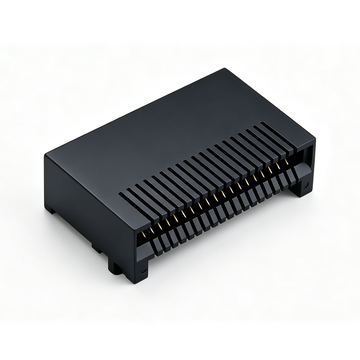
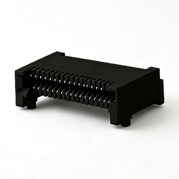
The TE Connectivity 1761987-9 is a 38-position QSFP+ receptacle connector designed for high-speed pluggable I/O applications. It features a right-angle, surface-mount configuration that provides the electrical connection between a QSFP+ module and its host PCB.
TE 1761987-9 Product Overview
TE 1761987-9 belongs to TE Connectivity's QSFP/QSFP+ connector portfolio and is designed for board-level integration in networking equipment.
Its primary product characteristics include:
-
Manufacturer: TE Connectivity
-
Part Number: 1761987-9
-
Product Description: Receptacle Connector Assembly
-
Form Factor: QSFP+
-
Number of Positions: 38
-
Connector Style: Receptacle
-
Mounting Type: Surface Mount, Right Angle
-
Termination Method: Solder
-
Contact Finish: Gold
-
Contact Pitch: 0.8mm
-
Packaging: Tape
The connector is mounted directly onto a printed circuit board and provides the mating interface for a compatible QSFP+ module. Its right-angle construction supports front-panel port integration in compact networking equipment.
TE identifies the component as an active product and provides a dedicated product drawing, CAD files, and technical specifications for engineering reference.
How the 38-Position QSFP+ Connector Works
The 38-position QSFP+ connector establishes an electrical connection between the module's edge contacts and the host PCB. Its contacts support high-speed differential signals, power delivery, grounding, and module-management functions.
The QSFP+ interface uses four transmit and four receive differential signal pairs, alongside supporting electrical contacts.
Its main functional groups include:
-
Transmit channels (Tx): Four differential pairs carrying data from the host to the module.
-
Receive channels (Rx): Four differential pairs carrying data from the module to the host.
-
Power contacts: Supply the operating voltage required by the module.
-
Ground contacts: Provide electrical reference and return paths.
-
Management signals: Support module selection, reset, low-power operation, and presence detection.
-
I2C interface: Provides serial communication between the host and module through SCL and SDA.
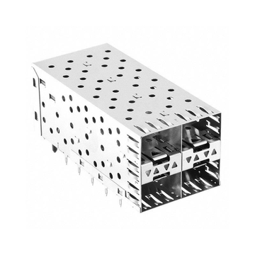
The receptacle works together with a QSFP+ cage, which guides the module during insertion and provides mechanical support and shielding. The connector and cage are separate components with different functions.
It is also important to distinguish the connector from the optical transceiver. The TE 1761987-9 is a passive electrical interconnect component; it does not perform optical-to-electrical or electrical-to-optical conversion.
Typical Applications of TE 1761987-9
The TE 1761987-9 is suitable for hardware designs incorporating QSFP+ pluggable interfaces, particularly equipment requiring high-density 40G connectivity.
Typical applications include:
-
40G Ethernet switches and routers.
-
Data center networking equipment.
-
Server network interface cards (NICs).
-
High-speed storage networking systems.
-
Communication and transmission equipment.
-
PCB assemblies incorporating QSFP+ cages and receptacles.
In these applications, connector selection affects mechanical integration, electrical performance, and manufacturing reliability. The receptacle must align correctly with the cage and front-panel opening while maintaining the required electrical characteristics.
TE 1761987-9 Datasheet: Technical Specifications and Key Parameters
The TE 1761987-9 datasheet identifies a 38-position QSFP+ connector with a maximum data-rate specification of 14Gb/s, a 0.8mm contact pitch, and surface-mount termination. These parameters provide the technical baseline for evaluating a compatible alternative.
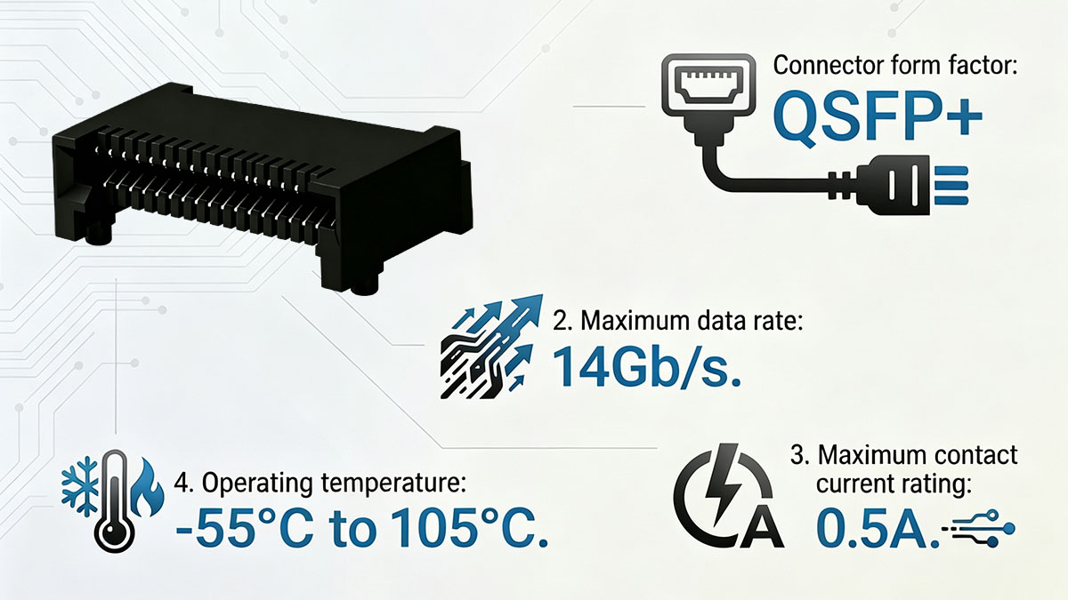
TE 1761987-9 Electrical and Mechanical Specifications
The following table summarizes the key specifications published by TE Connectivity.
|
Parameter |
TE 1761987-9 Specification |
|---|---|
|
Manufacturer |
TE Connectivity |
|
Part Number |
1761987-9 |
|
Product Family |
EVERCLEAR |
|
Form Factor |
QSFP+ |
|
Connector Style |
Receptacle |
|
Number of Positions |
38 |
|
Maximum Data Rate |
14Gb/s |
|
Contact Pitch |
0.8mm |
|
Mounting Type |
Surface Mount, Right Angle |
|
Termination Method |
Solder |
|
Contact Finish |
Gold |
|
Contact Finish Thickness |
0.76μm (30μin) |
|
PCB Termination Plating |
Tin |
|
Maximum Contact Current |
0.5A |
|
Recommended PCB Thickness |
1.45mm |
|
UL Flammability Rating |
UL 94V-0 |
These parameters describe the connector's contact arrangement, electrical capabilities, mounting configuration, and material characteristics. The 38-position configuration and 0.8mm pitch are particularly important when evaluating another QSFP+ receptacle.
The 14Gb/s figure is TE's published maximum data-rate specification for the connector. It should not be confused with the aggregate throughput of a complete QSFP+ module or networking port.
Operating Environment and Material Characteristics
The operating temperature range and material properties determine whether the connector is suitable for the intended equipment environment.
TE 1761987-9 has the following published characteristics:
-
Operating temperature: -55°C to 105°C.
-
Mating contact material: Gold-plated contacts.
-
Contact plating thickness: 0.76μm.
-
PCB termination plating: Tin.
-
Housing flammability: UL 94V-0.
-
Recommended PCB thickness: 1.45mm.
-
Sealable construction: No.
-
Circuit application: Signal.
The -55°C to 105°C operating temperature range is an important specification for applications exposed to demanding environmental conditions.
When selecting an alternative, engineers should compare the full operating range rather than assuming that matching connector dimensions guarantee equivalent environmental performance.
Important Datasheet Documents for Design Verification
TE provides several technical documents for the 1761987-9, covering mechanical dimensions, product performance, and application requirements.
The main references include:
-
Product drawing: ENG_CD_1761987_C1, showing the connector's mechanical dimensions and construction.
-
Product specification: 108-2234, covering product performance and qualification requirements.
-
Application specification: 114-13221, providing application and assembly guidance.
-
2D CAD files: Useful for PCB layout and dimensional comparison.
-
3D CAD models: Available in STEP, IGES, and 3D PDF formats for mechanical integration.
These documents are essential when evaluating a replacement connector. In particular, the product drawing should be used to verify dimensions, mounting geometry, and contact positioning.
TE 1761987-9 Cross Reference: LINK-PP LP11D000003
LINK-PP LP11D000003 is listed as a compatible alternative to TE 1761987-9. It features a 38-position QSFP+ receptacle, right-angle surface-mount construction, and gold-plated contacts, making it a relevant cross-reference for existing QSFP+ connector applications.
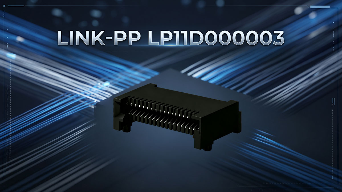
LINK-PP LP11D000003 Product Overview
LP11D000003 is a LINK-PP QSFP+ 1X1 receptacle connector designed for PCB-mounted high-speed I/O applications.
Its main product characteristics are:
-
Manufacturer: LINK-PP
-
Part Number: LP11D000003
-
Compatible TE Part Number: 1761987-9
-
Form Factor: QSFP+
-
Connector Style: Receptacle
-
Number of Positions: 38
-
Mounting Type: Surface Mount, Right Angle
-
Termination: Solder
-
Contact Finish: Gold
-
Packaging: Tape and Reel
-
Operating Temperature: -40°C to 85°C
-
UL Flammability Rating: UL 94V-0
The connector provides a board-level electrical interface for QSFP+ modules used in networking and high-speed communication hardware.
Its 38-position configuration and right-angle SMT mounting characteristics correspond to the main configuration of TE 1761987-9. LINK-PP also provides a product drawing and 3D model for engineering evaluation.
TE 1761987-9 vs. LINK-PP LP11D000003 Specification Comparison
The two connectors share several important product characteristics, including the QSFP+ form factor, 38-position configuration, receptacle design, and right-angle surface-mount construction.
The following comparison highlights their main specifications and the differences engineers should consider.
|
Specification |
TE 1761987-9 |
LINK-PP LP11D000003 |
|---|---|---|
|
Manufacturer |
TE Connectivity |
LINK-PP |
|
Part Number |
1761987-9 |
LP11D000003 |
|
Form Factor |
QSFP+ |
QSFP+ |
|
Connector Style |
Receptacle |
Receptacle |
|
Number of Positions |
38 |
38 |
|
Mounting Type |
Surface Mount, Right Angle |
Surface Mount, Right Angle |
|
Termination |
Solder |
Solder |
|
Contact Finish |
Gold |
Gold |
|
Operating Temperature |
-55°C to 105°C |
-40°C to 85°C |
|
UL Flammability |
UL 94V-0 |
UL 94V-0 |
|
Packaging |
Tape |
Tape and Reel |
The most important published specification difference is the operating temperature range. TE 1761987-9 supports -55°C to 105°C, while LINK-PP LP11D000003 is rated for -40°C to 85°C.
This difference should be considered carefully in industrial, outdoor, and temperature-sensitive networking applications. Although the two connectors share the same main configuration characteristics, LP11D000003 must meet the actual environmental requirements of the target equipment.
Why Consider LINK-PP LP11D000003 as a Cross-Reference Alternative?
LP11D000003 provides an alternative component for TE 1761987-9 applications, with corresponding QSFP+ form factor, contact count, and mounting characteristics.
Several characteristics make it relevant for engineering evaluation:
-
Matching connector configuration: Both products use a 38-position QSFP+ receptacle.
-
Similar mounting orientation: Both feature right-angle surface-mount construction.
-
Gold contact finish: Both specify gold-plated mating contacts.
-
PCB integration: Both use solder-based surface mounting.
-
Alternative component sourcing: LP11D000003 provides another option for QSFP+ hardware designs.
-
Technical documentation: LINK-PP provides a product drawing and 3D model for design review.
For hardware manufacturers maintaining existing PCB designs, an alternative connector can provide additional sourcing flexibility.
However, the product comparison should be followed by a detailed review of electrical contact mapping, mechanical dimensions, and PCB footprint compatibility before confirming a direct replacement.
Is LINK-PP LP11D000003 Pin-to-Pin Compatible with TE 1761987-9?
LINK-PP LP11D000003 is listed as compatible with TE 1761987-9 and shares its 38-position QSFP+ receptacle configuration. However, confirming complete pin-to-pin and drop-in compatibility requires checking the standardized QSFP+ contact functions against both manufacturers' connector drawings, including PCB terminal positions and mechanical dimensions.
Understanding Pin-to-Pin Compatibility for QSFP+ Connectors
The QSFP+ interface uses 38 electrical contacts to support high-speed data transmission, power delivery, grounding, and module management. These contacts are defined by the QSFP+ interface specification and provide the reference pin assignment for module-to-host connectivity.
The 38 contacts consist of:
-
Four transmit differential pairs (Tx1–Tx4), comprising eight contacts.
-
Four receive differential pairs (Rx1–Rx4), comprising eight contacts.
-
Ground contacts for signal and power reference.
-
Three power supply contacts.
-
Module management and control contacts, including SCL, SDA, ResetL, ModSelL, ModPrsL, IntL, and LPMode.
The following table presents the complete standard QSFP+ 38-contact module-side pin assignment based on SFF-8436.
|
Pin |
Signal |
Function |
|---|---|---|
|
1 |
GND |
Ground |
|
2 |
Tx2n |
Transmit Channel 2 Negative |
|
3 |
Tx2p |
Transmit Channel 2 Positive |
|
4 |
GND |
Ground |
|
5 |
Tx4n |
Transmit Channel 4 Negative |
|
6 |
Tx4p |
Transmit Channel 4 Positive |
|
7 |
GND |
Ground |
|
8 |
ModSelL |
Module Select |
|
9 |
ResetL |
Module Reset |
|
10 |
VccRx |
Receiver Power Supply |
|
11 |
SCL |
I2C Clock |
|
12 |
SDA |
I2C Data |
|
13 |
GND |
Ground |
|
14 |
Rx3p |
Receive Channel 3 Positive |
|
15 |
Rx3n |
Receive Channel 3 Negative |
|
16 |
GND |
Ground |
|
17 |
Rx1p |
Receive Channel 1 Positive |
|
18 |
Rx1n |
Receive Channel 1 Negative |
|
19 |
GND |
Ground |
|
20 |
GND |
Ground |
|
21 |
Rx2n |
Receive Channel 2 Negative |
|
22 |
Rx2p |
Receive Channel 2 Positive |
|
23 |
GND |
Ground |
|
24 |
Rx4n |
Receive Channel 4 Negative |
|
25 |
Rx4p |
Receive Channel 4 Positive |
|
26 |
GND |
Ground |
|
27 |
ModPrsL |
Module Present |
|
28 |
IntL |
Interrupt |
|
29 |
VccTx |
Transmitter Power Supply |
|
30 |
Vcc1 |
+3.3V Power Supply |
|
31 |
LPMode |
Low Power Mode |
|
32 |
GND |
Ground |
|
33 |
Tx3p |
Transmit Channel 3 Positive |
|
34 |
Tx3n |
Transmit Channel 3 Negative |
|
35 |
GND |
Ground |
|
36 |
Tx1p |
Transmit Channel 1 Positive |
|
37 |
Tx1n |
Transmit Channel 1 Negative |
|
38 |
GND |
Ground |
Source: SFF-8436, Table 3, Pin Function Definition.
This table describes the standardized QSFP+ module edge-contact interface. It should not be treated as a substitute for the actual receptacle terminal drawing. The orientation of the mating-side contacts and the PCB termination layout must be verified separately.
For a TE 1761987-9 cross-reference evaluation, engineers should compare the corresponding contact mapping in the TE and LINK-PP product drawings rather than assuming that identical position counts automatically establish identical terminal numbering.
PCB Footprint and SMT Mounting Compatibility
PCB footprint compatibility determines whether an alternative connector can be installed on an existing board without modifying its copper layout. Both TE 1761987-9 and LINK-PP LP11D000003 feature right-angle surface-mount construction, but their actual pad geometry must still be compared.
The following PCB characteristics should be checked:
-
SMT pad arrangement: Confirm that the contact pads occupy corresponding PCB locations.
-
Contact pitch: Verify the spacing between adjacent contact positions.
-
Connector outline: Compare overall length, width, and height.
-
Mounting orientation: Confirm the right-angle configuration and board-edge alignment.
-
Mechanical locating features: Check locating tabs, guides, and alignment structures.
-
Solder termination geometry: Compare pad dimensions and solder-joint requirements.
-
Cage alignment: Ensure that the receptacle aligns with the associated QSFP+ cage and front-panel opening.
TE specifies a recommended PCB thickness of 1.45mm for the 1761987-9. This dimension should be considered during mechanical evaluation.
For an accurate comparison, use TE's ENG_CD_1761987_C1 drawing alongside the LINK-PP LP11D000003 product drawing. Overlaying the corresponding dimensional references is more reliable than comparing product photographs.
Electrical and Mechanical Compatibility Verification
Electrical and mechanical compatibility must be evaluated together because matching the connector's external appearance does not guarantee equivalent contact performance or mating behavior.
Before approving LP11D000003 as a replacement, verify the following:
-
Contact assignments: Confirm that the 38 positions correspond to the intended QSFP+ interface functions.
-
Contact plating: Review mating contact material and plating thickness.
-
Current rating: Ensure that the connector supports the required current.
-
Signal integrity: Evaluate differential impedance, insertion loss, return loss, and crosstalk where applicable.
-
Mechanical retention: Check the connector's retention and mating stability.
-
Mating dimensions: Confirm alignment with the intended QSFP+ module and cage.
-
Environmental ratings: Compare operating temperature and applicable material requirements.
For high-speed networking equipment, signal integrity deserves particular attention. Differential signal pairs must maintain appropriate electrical characteristics throughout the connector transition and PCB routing.
A connector that fits mechanically but fails to meet the system's signal-integrity requirements can contribute to link instability and transmission errors.
Can LP11D000003 Replace TE 1761987-9 Without PCB Redesign?
LP11D000003 may serve as a replacement for TE 1761987-9 without PCB redesign when the electrical assignments, pad layout, mechanical dimensions, and assembly requirements are confirmed to match. A direct replacement should not be approved solely on the basis of the shared QSFP+ form factor and 38-position configuration.
A practical verification process includes:
-
Obtain the latest TE 1761987-9 and LINK-PP LP11D000003 product drawings.
-
Compare the 38-contact interface and corresponding electrical assignments.
-
Overlay the PCB footprint dimensions to identify pad-location differences.
-
Check connector height, mating geometry, and mechanical locating features.
-
Review temperature ratings and electrical performance requirements.
-
Assemble a prototype using LP11D000003.
-
Perform mechanical mating, continuity, and functional testing.
If the drawings confirm matching dimensions and the prototype passes the required tests, the alternative may be integrated into the existing PCB design without layout modifications.
If pad locations, mechanical features, or other critical dimensions differ, a PCB adjustment or alternative assembly approach may be necessary. This verification process helps reduce unnecessary rework during production.
TE 1761987-9 Compatible Connector: Replacement and Selection Considerations
Selecting a TE 1761987-9 compatible connector requires more than matching the QSFP+ form factor. Engineers should evaluate electrical assignments, PCB geometry, environmental ratings, and manufacturing requirements to determine whether an alternative meets the actual hardware design constraints.
Check the Connector Form Factor and Position Configuration
The first selection step is confirming that the alternative uses the same connector interface and contact configuration as the original component.
For a TE 1761987-9 cross-reference application, check the following:
-
QSFP+ receptacle configuration.
-
38-position contact arrangement.
-
Right-angle mounting orientation.
-
Surface-mount solder termination.
-
Compatible module mating interface.
-
Appropriate cage and front-panel integration.
These characteristics establish whether the candidate belongs to the correct connector category.
It is also important to distinguish QSFP+ from other pluggable connector formats. SFP+, QSFP28, QSFP-DD, and OSFP components may serve related networking applications, but their mechanical interfaces and electrical configurations are not automatically interchangeable.
Evaluate PCB Layout and Manufacturing Requirements
PCB integration determines whether a compatible connector can be installed reliably using the existing board design and assembly process.
Important manufacturing factors include:
-
Pad dimensions: Compare recommended copper pad sizes and spacing.
-
PCB thickness: Check board thickness against connector specifications.
-
Soldering process: Confirm compatibility with the intended SMT reflow process.
-
Component placement: Review pick-and-place orientation and placement tolerances.
-
Mechanical alignment: Verify the relationship between the receptacle, cage, and front panel.
-
Solder-joint quality: Inspect contact joints for bridging, insufficient solder, and other assembly defects.
For right-angle QSFP+ connectors, mechanical positioning is particularly important because the mating interface must align with the equipment's front-panel opening.
An incorrectly positioned connector can create module insertion or mating difficulties even when the electrical connections are correctly soldered.
Compare Environmental and Reliability Requirements
Operating temperature is one of the most important differences to review when selecting a connector alternative. A component that works under normal data center conditions may not satisfy the requirements of industrial or outdoor networking equipment.
For TE 1761987-9 and LINK-PP LP11D000003, the published operating temperature ranges are:
-
TE 1761987-9: -55°C to 105°C.
-
LINK-PP LP11D000003: -40°C to 85°C.
Engineers should also consider:
-
Contact material and plating thickness.
-
Housing material and flammability rating.
-
Mechanical retention under vibration.
-
Repeated insertion and removal requirements.
-
Humidity and environmental exposure.
-
Thermal cycling and long-term contact stability.
The alternative must meet the actual environmental requirements of the equipment. A matching connector style does not compensate for an insufficient temperature rating or an unmet reliability requirement.
Review Documentation and Supplier Technical Support
Complete technical documentation makes connector evaluation more efficient and reduces uncertainty during component substitution.
Before approving a cross-reference part, request or review:
-
Product drawings with dimensional tolerances.
-
2D PCB footprint information.
-
3D CAD models for mechanical integration.
-
Electrical and material specifications.
-
Operating temperature and environmental ratings.
-
Relevant quality and compliance documentation.
-
Prototype samples for engineering validation.
Technical support is also valuable when the original connector is already integrated into a production PCB. A supplier that can help compare product dimensions and interface requirements can make the evaluation process more straightforward.
For LINK-PP LP11D000003, the available product drawing and 3D model provide a starting point for comparing the connector with TE 1761987-9. Engineers should use the latest drawing revision when performing the final verification.
Common Applications and Integration Considerations for 38-Position QSFP+ SMT Connectors
38-position QSFP+ SMT connectors are commonly used in high-speed networking hardware that requires a compact electrical interface between pluggable modules and host PCBs. Their integration involves coordinating the receptacle, metal cage, PCB layout, and front-panel structure.
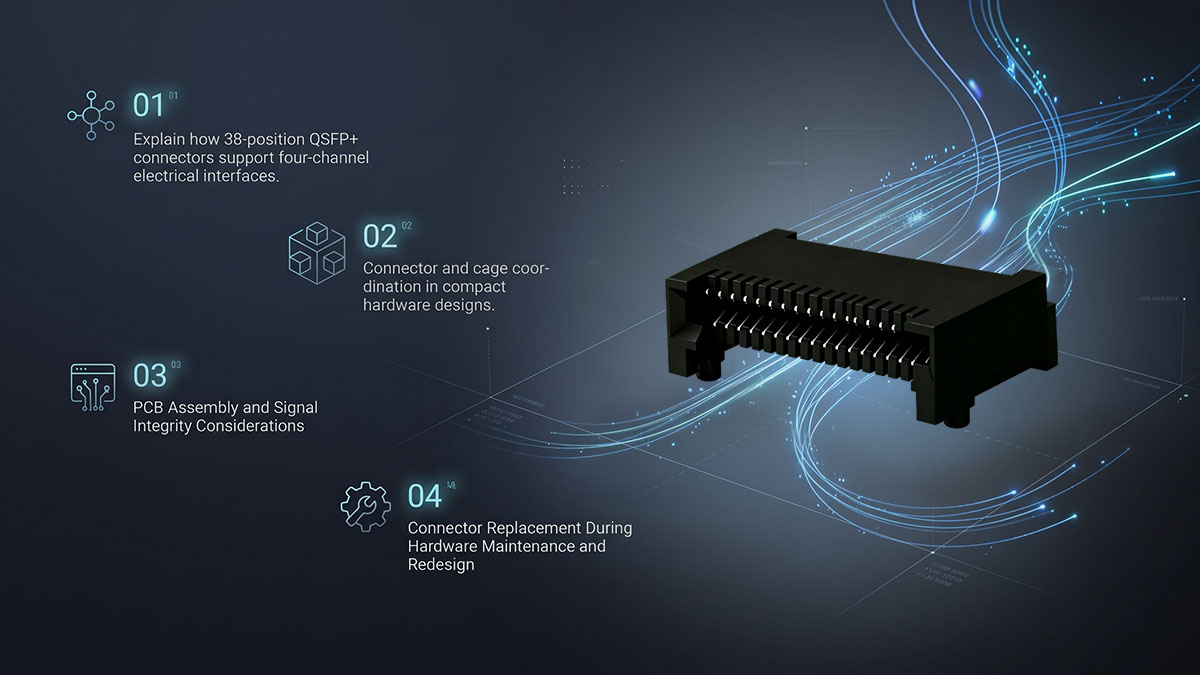
QSFP+ Connectors in 40G Ethernet Switches
QSFP+ connectors are widely used in 40G Ethernet equipment. They provide the electrical interface required for QSFP+ optical transceivers and direct-attach cable modules used in network switches.
Typical applications include:
-
40GBASE-SR4 optical module interfaces.
-
40GBASE-LR4 optical module interfaces.
-
40GBASE-ER4 optical module interfaces.
-
QSFP+ passive and active direct-attach cable interfaces.
-
High-density 40G Ethernet switch ports.
A QSFP+ interface uses four transmit and four receive electrical channels. In a typical 40G Ethernet implementation, each channel operates at approximately 10Gb/s, providing an aggregate nominal data rate of 40Gb/s.
The receptacle connector provides the electrical interface, while the optical transceiver or cable assembly determines the transmission medium and link characteristics.
QSFP+ Connector Integration in Data Center Hardware
Data center equipment uses QSFP+ connectors to support high-density network connectivity. Their right-angle mounting configuration helps integrate multiple ports into compact front-panel designs.
Common hardware applications include:
-
Ethernet switches: High-density 40G uplink and aggregation ports.
-
Core routers: High-speed connections between network processing and external interfaces.
-
Network interface cards: QSFP+ ports for server-to-switch connectivity.
-
Storage networking systems: High-bandwidth connections in storage infrastructure.
-
Communication equipment: Board-level interfaces in high-speed data transmission systems.
In these applications, the connector must work with the appropriate QSFP+ cage and front-panel structure. The cage provides module guidance and mechanical protection, while the receptacle establishes the electrical connection to the PCB.
These components should therefore be evaluated as part of the complete port assembly rather than independently.
PCB Assembly and Signal Integrity Considerations
Reliable QSFP+ performance depends on PCB routing, connector construction, and assembly quality. Because the interface carries high-speed differential signals, small electrical or mechanical inconsistencies can affect overall link performance.
Important design considerations include:
-
Differential pair routing: Maintain appropriate routing geometry and pair symmetry.
-
Impedance control: Design transmission paths according to the applicable QSFP+ electrical requirements.
-
Signal return paths: Provide sufficient ground continuity around high-speed signal transitions.
-
Crosstalk control: Maintain appropriate spacing and routing isolation between differential pairs.
-
PCB layer transitions: Minimize unnecessary vias and discontinuities.
-
SMT assembly: Follow the connector manufacturer's soldering and placement recommendations.
-
Mechanical alignment: Ensure the receptacle, cage, and front-panel opening remain properly aligned.
Prototype inspection should include solder-joint quality, connector positioning, and mechanical mating behavior.
For high-speed applications, electrical validation should also include suitable signal-integrity measurements. Visual inspection alone cannot establish whether a connector assembly meets the required transmission performance.
Connector Replacement During Hardware Maintenance and Redesign
Connector cross-references are particularly useful when maintaining existing networking hardware or updating a PCB design.
An alternative such as LINK-PP LP11D000003 can provide another component option for engineers evaluating TE 1761987-9 applications.
Common replacement scenarios include:
-
Existing connector sourcing constraints.
-
Hardware redesign involving alternative component suppliers.
-
Production continuity planning.
-
Maintenance of legacy networking equipment.
-
Standardization of connector components across multiple PCB designs.
-
Engineering evaluation of alternative QSFP+ receptacles.
However, replacing a connector in an existing design requires more attention than selecting a component for a new PCB.
For an existing design, the original footprint, mechanical envelope, and mating interface are already established. The alternative must satisfy these constraints or the PCB and mechanical design may need modification.
A drawing comparison followed by prototype testing is therefore the recommended approach.
Why Choose LINK-PP for TE 1761987-9 Compatible QSFP+ Connectors?
LINK-PP provides QSFP+ connector and cage solutions for networking and high-speed communication hardware, including LP11D000003 as a cross-reference option for TE 1761987-9. Our product portfolio supports engineers evaluating alternative components for PCB integration, equipment maintenance, and new hardware development.
LINK-PP LP11D000003: A Direct Cross-Reference Option
LINK-PP LP11D000003 is the corresponding product to evaluate when looking for a TE 1761987-9 cross-reference. It shares the original connector's main configuration characteristics, including its 38-position QSFP+ receptacle and right-angle SMT mounting.
Its key characteristics include:
-
38-position QSFP+ receptacle.
-
Surface-mount, right-angle configuration.
-
Solder termination.
-
Gold contact finish.
-
Tape-and-reel packaging.
-
UL 94V-0 flammability rating.
-
Operating temperature of -40°C to 85°C.
For engineering teams, LP11D000003 offers an alternative component to assess against the existing TE connector specification.
The most important consideration remains the operating temperature difference. Projects originally designed around the full -55°C to 105°C range of TE 1761987-9 should verify that the LINK-PP alternative meets the actual environmental requirements.
Likewise, PCB footprint and pin assignment comparisons should be completed before confirming a direct replacement.
LINK-PP QSFP+ Connector and Cage Product Portfolio
LINK-PP offers QSFP+ connector and cage solutions for high-speed networking equipment. These products address different parts of the QSFP+ port assembly and support engineers working on board-level interconnect designs.
The main product categories include:
-
QSFP+ receptacle connectors: PCB-mounted electrical interfaces for pluggable QSFP+ modules.
-
QSFP+ cage assemblies: Metal enclosures that provide module guidance, shielding, and mechanical support.
-
Single-port solutions: Connector and cage configurations for individual QSFP+ interfaces.
-
Multi-port solutions: Configurations designed for higher-density networking equipment.
When selecting these components, engineers should distinguish between the receptacle and the cage. A compatible receptacle does not automatically guarantee that an existing cage assembly can be reused.
For complete port integration, both mechanical compatibility and electrical interface requirements must be considered.
Product Documentation, Quality, and Technical Support
Technical documentation and product consistency are important when evaluating alternative connectors for production hardware.
At LINK-PP, we support connector evaluation through product information and technical assistance covering relevant application requirements.
Engineering teams can refer to:
-
Product drawings for dimensional verification.
-
Connector specifications for electrical and mechanical evaluation.
-
Mounting information for PCB integration.
-
Product configuration details for component selection.
-
Technical assistance for cross-reference evaluation.
-
Quality and compliance information where applicable.
For projects involving TE 1761987-9, engineers can provide the original part number, PCB drawing, and application requirements to help identify the relevant LINK-PP alternative.
This makes it easier to evaluate whether LP11D000003 is appropriate for a particular design rather than relying only on general connector descriptions.
Explore LINK-PP LP11D000003 and Related QSFP+ Products
Engineers looking for a TE 1761987-9 alternative can start with the LINK-PP LP11D000003 product page to review its specifications and available product drawing.
Useful next steps include:
-
Visit the LINK-PP LP11D000003 product page.
-
Review the 38-position QSFP+ connector specifications.
-
Compare the product drawing with the original TE 1761987-9 footprint.
-
Use the LINK-PP compatibility tool to check product alternatives.
-
Contact the technical team for application-specific questions and request a quotation.
The same evaluation process can also be applied when exploring other QSFP+ receptacles and cage assemblies within the LINK-PP portfolio.
For engineering projects requiring an alternative component, reviewing the technical documentation before production integration helps ensure that the selected connector meets the necessary design and operating requirements.
Conclusion
LINK-PP LP11D000003 is a listed compatible alternative to the TE 1761987-9 38-position QSFP+ SMT connector. Both products share a QSFP+ receptacle configuration, right-angle surface-mount construction, and gold-plated mating contacts, making LP11D000003 a relevant option for engineers evaluating alternative connector solutions.
Before confirming a replacement, focus on four essential considerations:
-
Connector configuration: Both components feature a 38-position QSFP+ receptacle design.
-
PCB compatibility: Verify contact assignments, SMT pad geometry, mechanical dimensions, and mounting alignment.
-
Operating environment: Account for the different temperature ratings of the two connectors.
-
Functional validation: Perform prototype assembly, mechanical mating, and electrical testing before production approval.
If you are evaluating a TE 1761987-9 cross reference for an existing networking product or a new PCB design, LINK-PP can help identify the appropriate connector solution.
Visit the LINK-PP Official Store to explore LP11D000003 and related QSFP+ connector products. For additional sourcing confidence, LINK-PP offers 15-day no-reason returns and exchanges for standard-stock items. If a product has a quality issue, also covers the return shipping cost. Our goal is to make connector selection and component sourcing more straightforward, with technical assistance available throughout the evaluation process.