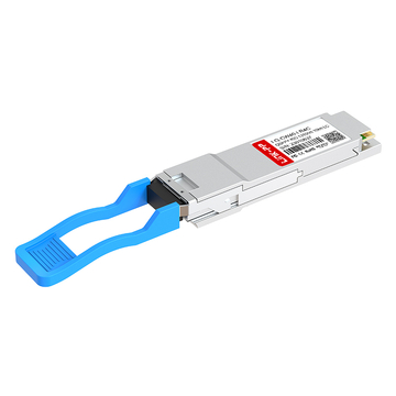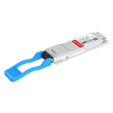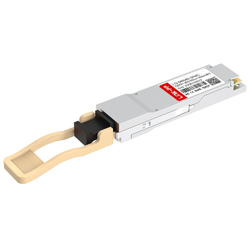
In modern enterprise and data-center networks, 40G QSFP+ transceivers are essential for achieving high-speed, low-latency connectivity. Selecting the right 40G module requires careful consideration of technical compatibility, including SR4, LR4, ER4, and DAC/AOC types, connector standards such as MPO-12 or LC duplex, fiber reach over OM3/OM4 multimode or OS2 single-mode, and power and thermal characteristics.
Network engineers and IT managers frequently evaluate factors such as vendor compatibility (Cisco, Juniper, Arista), transmission distance, breakout support, and monitoring features like DOM/DDM to ensure reliable operation. Procurement decisions also involve assessing pricing, warranty coverage, and bulk order options, as well as requesting sample units for validation before large-scale deployment.
Buyers searching for “QSFP+ module price,” “QSFP+ compatible with Cisco,” or “bulk QSFP+ order” generally focus on three priorities: fit (technical match), compatibility (interoperability), and purchase risk mitigation (warranty and returns). This article addresses these priorities directly and includes practical checks that can be applied when engaging with suppliers prior to placing an order.
This article provides a comprehensive overview of 40G QSFP+ transceivers, including technical specifications, compatibility considerations, procurement best practices, and deployment guidance. It is intended to help buyers make informed purchasing decisions, reduce operational risks, and ensure optimal performance in enterprise and data-center networks.
1️⃣ Understanding QSFP+ and 40G Options
QSFP+ transceivers are key building blocks for high-speed data-center, enterprise, and telecom networks. They provide 40 Gbps optical connectivity over multimode or single-mode fiber and can also support breakout configurations to deliver 4×10G to downstream SFP+ ports. Selecting the right module requires understanding the technical characteristics, optical variants, physical form factors, and industry standards that define interoperability and performance. This section explains the fundamentals, the common 40G QSFP+ types, and their deployment scenarios.
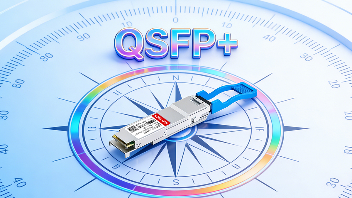
What “QSFP+” means in practice
QSFP+ (Quad Small Form-factor Pluggable Plus) is a hot-pluggable, MSA-defined form factor that maps four 10 Gbps electrical lanes into one pluggable interface. In practice, QSFP+ supports native 40G operation (40GBASE variants) and can often be used in breakout configurations to deliver 4×10G to downstream SFP+ ports. The QSFP family is defined mechanically and electrically by industry MSA (multi-source agreement) documents; vendors implement optics and cable assemblies (SR4 / LR4 / ER4 / ZR4, DAC, AOC) that fit the QSFP+ envelope.
Common 40G variants and their typical use cases
-
40GBASE-SR4 — Parallel multimode fiber (MPO-12). Typical for short-range intra-rack or adjacent-rack links in data centers. Works with OM3/OM4 fiber; expected reach usually quoted as ~100 m on OM3 and ~150 m on OM4 under standard test conditions.
-
40GBASE-LR4 — Single-mode, 4-wavelength CWDM or wavelength-multiplexed, typically deployed for 10 km class links using LC duplex connectors and single-mode fiber (OS2).
-
40GBASE-ER4 / 40GBASE-ZR4 — Extended reach single-mode variants for metro and long-haul links; require careful power-budget planning and often fiber amplification or dispersion management for very long distances.
-
DAC (Direct Attach Copper) — Passive twinax cables for very short links (common up to 3–7 m) offering the lowest cost and latency, typically used inside racks or between adjacent racks.
-
AOC (Active Optical Cable) — Fixed-length active optical assemblies offering longer short-reach connectivity (commonly up to tens of meters) while simplifying handling relative to separate transceivers and patching.
QSFP+ Variant Overview
| Variant | Fiber Type | Connector | Typical Reach | Power | Applications |
|---|---|---|---|---|---|
| SR4 | OM3/OM4 | MPO-12 | 100–150 m | 1.0–1.5 W | Rack-to-rack, 4×10G breakout |
| LR4 | OS2 | LC Duplex | 10 km | 3.0–3.5 W | Campus & metro links |
| ER4 | OS2 | LC Duplex | 40 km | 3.5+ W | Metro aggregation |
| ZR4 | OS2 | LC Duplex | 80+ km | 3.5+ W | Long-haul backbone |
| DAC | Twinax | N/A | 1–7 m | <1–2 W | TOR, short rack links |
| AOC | Active Optical | N/A | 10–30 m | 2–2.5 W | Dense rack/inter-row links |
Standards and MSA Compliance
QSFP+ modules are defined and regulated by industry standards and Multi-Source Agreements (MSAs) to ensure mechanical, electrical, and optical interoperability across vendors and host devices.
Key standards include:
-
SFF-8436: QSFP+ mechanical and electrical specification, defines dimensions, pinout, and connector types
-
SFF-8472: Digital Optical Monitoring (DOM/DDM) specification, mandatory for telemetry of temperature, Vcc, TX/RX optical power
-
IEEE 802.3ba: Defines 40GBASE standards including SR4, LR4, ER4, and ZR4
-
Vendor MSAs: Many manufacturers follow MSA guidelines for optical power, wavelength tolerance, and DOM reporting
Compliance considerations:
-
Ensure that QSFP+ modules conform to SFF-8436 for host card compatibility
-
DOM compliance (SFF-8472) is critical for NOC monitoring and proactive maintenance
-
IEEE 802.3 compliance guarantees that the module will meet link budgets, dispersion tolerance, and lane signaling standards
Engineering notes:
-
Non-compliant or “generic” modules may work initially but can trigger “unsupported module” warnings in enterprise switches
-
Always validate EEPROM content, vendor OUI, and firmware compatibility before bulk procurement
2️⃣ Technical Selection and Design Considerations for 40G QSFP+ Modules
Selecting the appropriate 40G QSFP+ module is a multi-factor decision that depends on link distance, fiber type, power and thermal constraints, and monitoring requirements. Correct optical selection, mechanical and electrical validation, and operational monitoring are essential to ensure reliable performance and minimize downtime. This section outlines step-by-step guidance to match optics to your network requirements, manage thermal and power budgets, and integrate DOM/DDM telemetry into operational workflows.
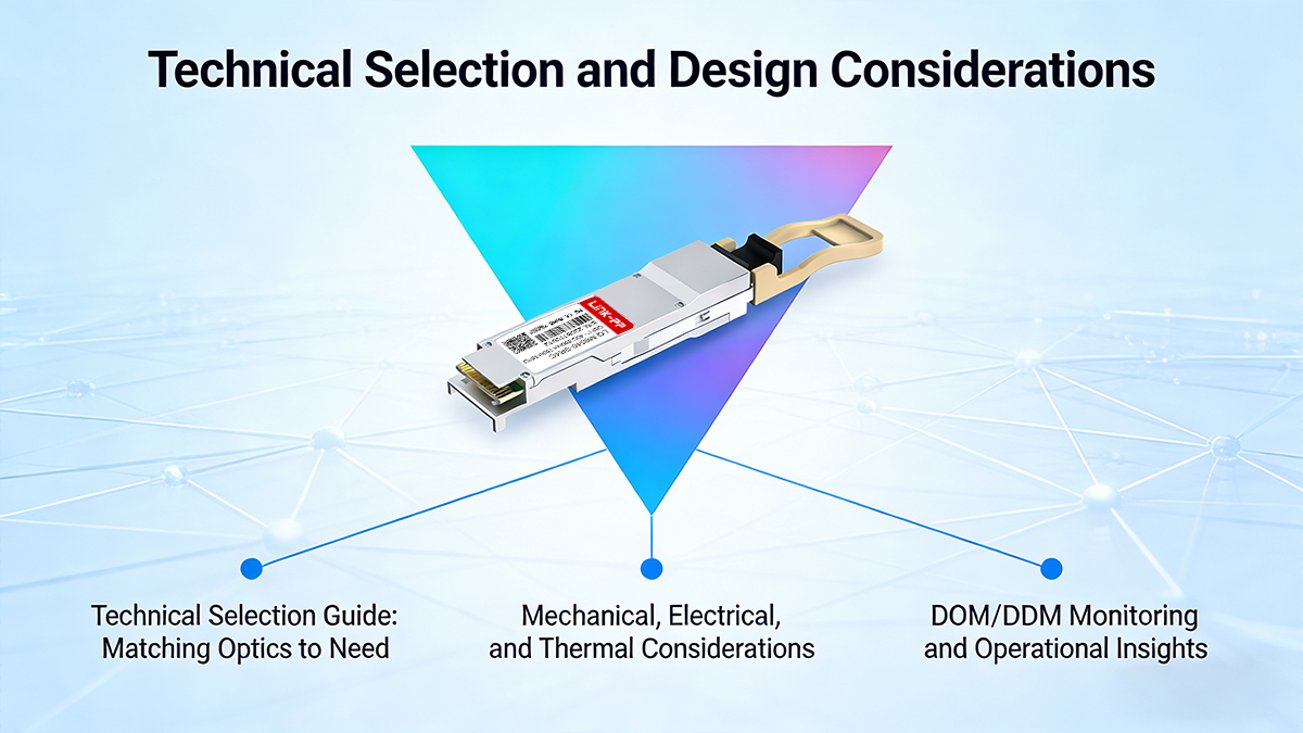
1. Technical Selection Guide: Matching Optics to Need
Here, we guide buyers through the process of selecting the correct QSFP+ module for a given link. This includes distance, fiber type, breakout requirements, and link budget calculations, ensuring both technical fit and reliable network operation.
Step 1 — Define the link and environment
For each link identify:
-
Distance and path (rack-to-rack, row-to-row, building-to-building).
-
Fiber plant: single-mode (OS2) or multimode (OM3/OM4), and the connectors and patch panel configuration.
-
Port density and thermal constraints: high-density linecards will raise ambient temperature; plan for optical modules’ thermal derating.
-
Operational monitoring needs: whether DOM/DDM metrics are required by NOC processes.
Step 2 — Choose the optical type by distance and topology
-
Use SR4 (MPO) only when the fiber plant is multimode and distances are within the SR4 specification. SR4 simplifies rack-to-rack cabling but requires MPO termination discipline and careful patch pane/patch cord planning when doing 4×10G breakout.
-
Choose LR4 when single-mode runs approach 10 km; LR4 requires LC duplex and single-mode fiber.
-
Choose ER4/ZR4 only when there is a validated power budget for the desired distance; these may require dispersion-compensating measures in longer metro links.
-
Use DAC for sub-7 m connections when the switch vendor supports passive twinax; DAC reduces cost and power but is fixed-length and less flexible.
-
Use AOC where a lightweight, longer-than-DAC cable is needed with lower heat conduction than copper.
Step 3 — Calculate or confirm the link budget (high level)
For single-mode systems:
-
Obtain transmitter output power (dBm) and receiver sensitivity (dBm) from datasheets.
-
Subtract expected link loss (fiber attenuation + splice/connector losses). For 1310 nm, a conservative attenuation estimate is 0.4 dB/km in installed fiber plus ~0.5 dB per connector/panel segment; multiply and sum accordingly.
-
Include margin for aging, temperature, and manufacturing variances; a typical engineering margin is 3–6 dB depending on criticality.
For multimode:
-
Use vendor-reported modal bandwidth and OM class (OM3/OM4); rely on measured reach published by the module vendor rather than an optimistic theoretical calculation, since modal dispersion and launch conditions vary.
Procurement check: require suppliers to provide measured link reports (or sample units) for critical links rather than accepting nominal maximum distances.
2. Mechanical, Electrical, and Thermal Considerations
Form Factor & Pinout
-
QSFP+40G modules follow SFF-8436 mechanical/electrical spec
-
Confirm host card compatibility if using non-standard carriers
-
Verify pinout and electrical lane mapping to avoid signaling errors
Power Consumption & Thermal Management
-
Typical 40G QSFP+ module power ranges:
-
SR4: 1.0–2.0 W
-
LR4: 3.0–3.5 W
-
ER4/ZR4: ≥3.5 W
-
-
High-density switches may require airflow adjustments or lower-power optics
-
Thermal derating curves should be requested from vendors
Engineering Practices:
-
Track cabinet ambient temperature and airflow before deployment
-
Ensure cooling is sufficient for worst-case conditions
-
Validate power vs temperature performance on densely populated linecards
Procurement Clause: Include a requirement that vendors provide thermal derating curves and lab-tested results for your specific deployment environment.
3. DOM/DDM Monitoring and Operational Insights
Digital Optical Monitoring (DOM)
-
Provides telemetry: module temperature, Vcc, TX/RX optical power, and bias current
-
Standardized by SFF-8472
-
Enables proactive maintenance and early fault detection
Operational Integration:
-
Integrate DOM metrics into NOC dashboards
-
Set thresholds for proactive alerts (e.g., TX power drop >2 dB)
-
Use DOM during interoperability testing to confirm stability under sustained load
Sample DOM Readings:
| Metric | Typical Value (SR4) | Typical Value (LR4) | Notes |
|---|---|---|---|
| Temperature | 35°C | 40°C | Measured under nominal load |
| Vcc | 3.3 V | 3.3 V | Stable ±0.05 V |
| TX Power | –1 dBm | +2 dBm | Verify against datasheet |
| RX Power | –7 dBm | –8 dBm | Monitor drop during operation |
Procurement Requirement:
-
Mandate SFF-8472 compliant DOM
-
Request sample I²C readout or DOM log with first delivery
-
Ensure vendor provides long-term stability metrics for thermal and power monitoring
Operational Best Practices:
-
Document baseline DOM readings for each lot and SKU
-
Monitor trends to detect early degradation
-
Maintain sample spares from validated lot codes for replacement
3️⃣ QSFP+ Transceivers Compatibility & Interoperability
Compatibility and interoperability are critical factors when deploying QSFP+ 40G transceivers across enterprise, cloud, and telecom networks. Even when optical performance meets IEEE and MSA standards, differences in switch firmware, EEPROM encoding, and vendor enforcement policies can cause link instability or “unsupported module” errors. A structured validation and verification workflow ensures stable operation across heterogeneous platforms and significantly reduces deployment risk before bulk procurement.
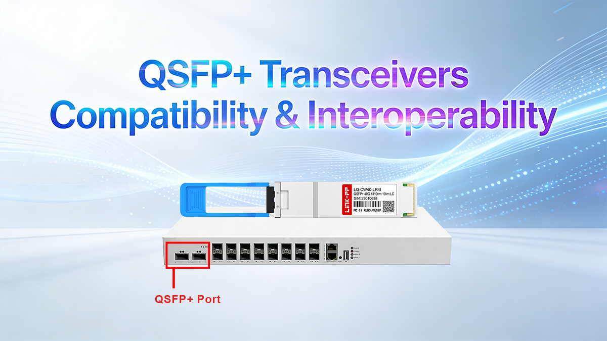
Lab Validation Workflow
A streamlined laboratory validation workflow helps confirm real-world interoperability without excessive testing overhead. For most enterprise and data-center environments, the following five-step process provides sufficient engineering confidence.
1. Platform and Firmware Mapping
Identify all target switch models and firmware versions currently deployed and scheduled for upgrade. Prioritize validation on high-density line cards and core aggregation platforms.
2. Sample-Based Functional Testing
Test at least two sample units per SKU to verify link establishment, breakout behavior (if applicable), and basic traffic forwarding at full 40G line rate.
3. Sustained Traffic and Stability Validation
Run continuous traffic at ≥95% utilization for 6–12 hours, monitoring packet loss, CRC errors, and link stability. This step reveals marginal optical performance and firmware incompatibilities.
4. Thermal and Power Behavior Check
Validate module temperature, voltage, and optical output under typical and elevated ambient conditions. Confirm that thermal derating does not introduce link instability in dense port deployments.
5. Documentation and Approval
Record validated switch models, firmware revisions, and operating conditions. This compatibility matrix becomes the baseline for production rollout and future firmware upgrades.
Recommended Validation Checklist
| Item | Recommendation |
|---|---|
| Sample quantity | ≥2 units per SKU |
| Test duration | ≥6 hours sustained load |
| Firmware coverage | Current + planned versions |
| Breakout testing | If used |
| Thermal observation | Mandatory |
This pragmatic workflow balances engineering rigor and procurement efficiency, allowing buyers to validate interoperability without excessive lab overhead.
EEPROM and Vendor OUI Verification
Many enterprise-class switches implement EEPROM and vendor OUI validation to enforce approved optics policies. When third-party modules do not match recognized vendor signatures, switches may generate “unsupported module” warnings, disable diagnostic functions, or block the port entirely.
Why EEPROM Matters
Each QSFP+ transceiver stores vendor identity, optical parameters, and compliance information in its onboard EEPROM. Switch firmware reads this data during initialization and may compare it against internal allow-lists.
Typical Enforcement Behavior
| Switch Vendor | Enforcement Level |
|---|---|
| Cisco | Strict validation |
| HPE / Aruba | Model-dependent |
| Juniper | Moderate |
| Arista | Generally permissive |
Risk Mitigation Strategies
-
Pre-validated encoding: Work with suppliers offering platform-compatible EEPROM profiles.
-
Firmware-aware testing: Validate modules on both current and planned firmware releases.
-
Dual-source qualification: Maintain at least two qualified suppliers to reduce operational and supply-chain risk.
Procurement Contract Clauses
Compatibility Commitment
Supplier guarantees interoperability with the following platforms and firmware versions: [list]. Modules triggering unsupported module errors or link instability shall be replaced at no cost.
EEPROM Disclosure
Supplier shall provide EEPROM identification data and confirm vendor OUI compatibility prior to shipment.
Firmware Forward Compatibility
Supplier guarantees compatibility for firmware upgrades released within the next 24 months.
A focused compatibility and interoperability strategy — combining targeted lab validation with disciplined EEPROM verification — transforms QSFP+ procurement into a controlled engineering process rather than a trial-and-error exercise. This approach significantly reduces deployment risk, accelerates production rollout, and safeguards long-term operational stability.
4️⃣ Pricing Strategy and Total Cost of Ownership (TCO)
Pricing for 40G QSFP+ transceivers is influenced by optical technology, performance validation, vendor brand positioning, and service commitments. However, procurement decisions based solely on unit price often lead to higher long-term operational costs. This section explains the key price drivers and introduces a structured Total Cost of Ownership (TCO) model to help buyers make economically optimal decisions across deployment, maintenance, and lifecycle management.
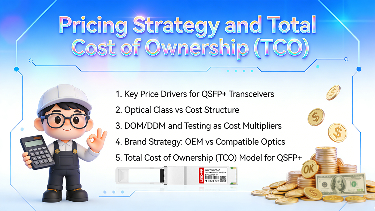
1. Key Price Drivers for QSFP+ Transceivers
| Cost Factor | Impact on Price | Engineering Rationale |
|---|---|---|
| Optical class (SR4 / LR4 / ER4) | High | Long-reach modules require WDM optics, higher-grade lasers, tighter manufacturing tolerances, and more complex DSP |
| Transmitter type | Medium–High | VCSEL (SR4) < DFB (LR4) < EML (ER4) in cost and performance |
| DOM/DDM support & calibration | Medium | Requires additional circuitry, firmware tuning, and temperature compensation |
| Testing & validation level | Medium | Burn-in, BER testing, interoperability validation add manufacturing and QA cost |
| Brand & warranty terms | Medium–High | OEM optics include platform warranty coverage; reputable third-party vendors provide equivalent SLAs at lower pricing |
| Procurement volume | High | Large volume orders unlock tiered discounts and customized service terms |
2. Optical Class vs Cost Structure
Optical design is the primary cost driver in QSFP+ modules.
| Module Type | Typical Cost Level | Key Cost Drivers |
|---|---|---|
| 40G-SR4 | Low | VCSEL lasers, MMF optics, simpler driver circuitry |
| 40G-LR4 | Medium | WDM optics, DFB lasers, precise wavelength control |
| 40G-ER4 | High | EML lasers, advanced DSP, thermal stabilization |
| DAC / AOC | Very Low → Medium | Passive copper vs active fiber electronics |
Engineering insight:
SR4 modules benefit from parallel MMF optics and VCSEL transmitters, enabling lower-cost manufacturing. LR4 and ER4 rely on wavelength multiplexing and tighter wavelength stability, which significantly increases optical complexity and yield sensitivity.
3. DOM/DDM and Testing as Cost Multipliers
Fiber Modules with fully validated DOM/DDM and documented test reports typically command higher prices, but provide measurable operational value:
-
Real-time monitoring of:
-
Tx optical power
-
Rx optical power
-
Module temperature
-
Bias current
-
Supply voltage
-
-
Faster fault localization
-
Reduced mean time to repair (MTTR)
-
Predictive maintenance capability
Commercial impact:
Well-calibrated DOM reduces unnecessary site visits, lowers troubleshooting labor, and improves network uptime — directly improving long-term cost efficiency.
4. Brand Strategy: OEM vs. Compatible Optics
| Category | OEM-Branded Optics | High-Quality Compatible Optics |
|---|---|---|
| Unit price | Very high | 40–70% lower |
| Hardware design | Proprietary | MSA-compliant |
| Firmware locking | Often restricted | Vendor-coded compatibility |
| Warranty handling | Platform integrated | Independent SLA |
| Lead time | Often long | Usually faster |
Procurement reality:
Enterprise buyers increasingly deploy certified compatible optics for large-scale rollouts, while reserving OEM modules for warranty-critical or regulatory-sensitive deployments.
5. Total Cost of Ownership (TCO) Model for QSFP+ Procurement
Instead of evaluating only purchase price, professional buyers calculate TCO across the full module lifecycle.
Core TCO Formula:
TCO=Cunit+Cfailure+Cdowntime+Cinventory\text{TCO} = C_{unit} + C_{failure} + C_{downtime} + C_{inventory}
Where:
-
C_unit = Unit price × quantity
-
C_failure = Expected failure rate × RMA logistics × labor
-
C_downtime = Estimated business impact of link failure
-
C_inventory = Cost of spare stock holding
Practical TCO Cost Components
| Cost Component | Typical Contribution |
|---|---|
| Unit acquisition | 35–55% |
| Failure replacement (RMA + labor) | 10–20% |
| Downtime risk exposure | 20–35% |
| Inventory holding | 5–10% |
Example TCO Comparison
Scenario: 200 × 40G QSFP+ LR4 modules for data center interconnect
| Parameter | OEM Modules | Certified Compatible |
|---|---|---|
| Unit price | $2,400 | $720 |
| Hardware cost | $480,000 | $144,000 |
| Estimated failure rate | 0.3% | 0.5% |
| Annual RMA + labor | $4,200 | $6,000 |
| Downtime exposure | $12,000 | $8,000 (advanced replacement SLA) |
| Inventory cost | $18,000 | $6,500 |
| 3-Year TCO | $514,200 | $164,500 |
Result:
Certified compatible optics reduce 3-year TCO by ~68%, while maintaining equivalent operational performance.
6. Procurement Optimization Strategy
To minimize long-term ownership cost, enterprise buyers typically:
-
Negotiate volume-tier pricing
-
50–100 pcs
-
100–300 pcs
-
300+ pcs
-
-
Include advanced replacement SLAs
-
24–48h global RMA dispatch
-
Optional on-site spares management
-
-
Request full validation documentation
-
BER test reports
-
Interoperability validation matrix
-
Temperature & aging test results
-
-
Standardize vendor qualification
-
Reduces firmware compatibility risks
-
Simplifies inventory and sparing models
-
Buyer Checklist: Pricing Evaluation
Before placing bulk QSFP+ orders, confirm:
-
✔ Optical class correctly matched to distance
-
✔ DOM/DDM fully supported and calibrated
-
✔ Compatibility coding verified
-
✔ Volume discount tiers defined
-
✔ RMA and advanced replacement SLA confirmed
-
✔ Lifecycle support period ≥ 5 years
5️⃣ 40G QSFP+ Deployment, Operations, and Troubleshooting Tips
Successful deployment of 40G QSFP+ transceivers depends not only on selecting the correct optical specification, but also on proper installation practices, airflow and thermal design, fiber management, and systematic troubleshooting procedures. This section provides field-proven guidance for dense port deployments, operational best practices, and structured fault isolation workflows to maximize link reliability and minimize service disruption.
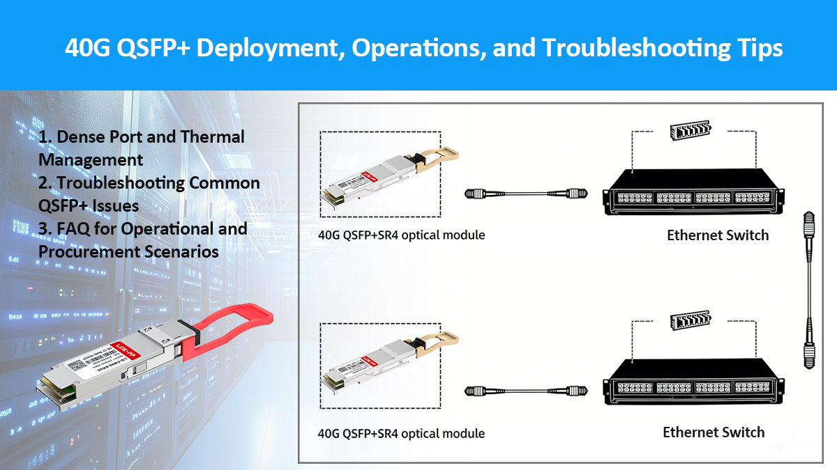
▶ Dense Port and Thermal Management
High-density 40G deployments are common in spine–leaf data center architectures, campus core switches, and aggregation routers. In these environments, thermal stability, airflow direction, and port utilization strategy directly affect long-term optical reliability.
1. Airflow Direction and Rack-Level Planning
QSFP+ modules typically support front-to-back (F2B) or back-to-front (B2F) airflow depending on the host switch design.
| Airflow Type | Typical Application |
|---|---|
| Front-to-back | Hot aisle / cold aisle data center layouts |
| Back-to-front | Telecom central offices and carrier edge nodes |
Best practices:
-
Always match transceiver airflow orientation to switch airflow design.
-
Avoid mixing airflow directions in the same rack.
-
Maintain ≥ 150 mm clearance in front of port panels for fiber bend radius and airflow.
2. Power Density and Thermal Budgeting
Typical QSFP+ power dissipation:
| Module Type | Typical Power |
|---|---|
| 40GBASE-SR4 | 1.2 – 1.5 W |
| 40GBASE-LR4 | 3.0 – 4.5 W |
| 40GBASE-ER4 | 4.0 – 5.0 W |
| Active Optical Cable (AOC) | 1.5 – 2.0 W |
Engineering implications:
-
A fully populated 32-port QSFP+ switch using LR4 optics can dissipate over 140 W of optical heat load alone.
-
Ensure switch chassis supports adequate fan redundancy and airflow CFM.
-
Avoid deploying high-power ER4 modules in poorly ventilated environments.
3. Fiber Routing and Mechanical Stress Control
Improper fiber handling is a major contributor to intermittent link failures.
Recommended guidelines:
-
Maintain minimum bend radius ≥ 30 mm for OM4 multimode fiber.
-
For single-mode fiber, maintain ≥ 20× cable diameter bend radius.
-
Use horizontal cable managers and strain relief brackets.
-
Avoid vertical tension loads on MPO/MTP trunk cables.
4. Port Density Optimization Strategies
For large-scale deployments:
-
Use MPO-to-LC breakout harnesses strategically to balance port utilization.
-
Standardize fiber polarity management using Type-B or Type-C trunks.
-
Implement structured cabling maps for simplified fault tracing.
▶ Troubleshooting Common QSFP+ Issues
This section provides a systematic troubleshooting framework for identifying and resolving typical QSFP+ Module operational problems.
1. Module Not Detected / Unsupported Module Error
Common causes:
-
EEPROM vendor ID mismatch
-
Firmware whitelist enforcement
-
Faulty electrical contact
Resolution workflow:
-
Verify firmware version of switch.
-
Check module vendor OUI and part number via CLI.
-
Re-seat the transceiver.
-
Test in alternate port or switch.
-
Apply vendor-certified firmware coding if necessary.
2. Link Up But High Packet Loss or CRC Errors
| Possible Cause | Diagnostic Method | Corrective Action |
|---|---|---|
| Fiber contamination | Visual inspection + cleaning | Clean MPO ferrules |
| Polarity mismatch | Optical power imbalance | Correct polarity |
| Excessive link loss | DOM Rx power reading | Recalculate link budget |
| Dispersion issues | Long SMF spans | Replace ER4 optics |
3. Link Flapping or Intermittent Connectivity
Root causes:
-
Marginal receive sensitivity
-
Excessive temperature fluctuation
-
Mechanical fiber stress
Mitigation steps:
-
Monitor DOM temperature and Rx power trend.
-
Improve airflow or reduce port density.
-
Replace suspect patch cords.
4. Optical Power Out-of-Range Alarms
Typical alarm thresholds:
| Parameter | Warning | Alarm |
|---|---|---|
| Tx power | ±3 dB from nominal | ±5 dB |
| Rx power | > –2 dBm | < –13 dBm |
| Temperature | 70°C | 80°C |
Engineering interpretation:
-
High Rx power may require optical attenuators.
-
Low Rx power often indicates fiber attenuation or connector contamination.
▶ FAQ for Operational and Procurement Scenarios
Q1: Can QSFP+ modules be hot-swapped?
Yes.
All compliant QSFP+ modules support hot-plugging. However:
-
Avoid hot-swapping under full traffic load.
-
Always observe ESD precautions.
Q2: How many times can a QSFP+ module be inserted and removed?
Typical mechanical life: ≥ 100 insertion cycles.
For mission-critical networks, reuse of optics across multiple redeployments is discouraged.
Q3: Can QSFP+ LR4 operate over OM4 multimode fiber?
No.
LR4 modules are designed strictly for single-mode fiber (OS2). Attempting to use MMF results in severe coupling loss.
Q4: What is the recommended spare ratio for QSFP+ optics?
| Network Size | Spare Ratio |
|---|---|
| <100 modules | 5–10% |
| 100–500 modules | 3–5% |
| >500 modules | 2–3% |
Q5: How do I evaluate vendor quality before bulk purchasing?
Key evaluation criteria:
-
Documented interoperability validation
-
DOM calibration accuracy reports
-
Burn-in and aging test methodology
-
RMA turnaround SLA
-
Real production traceability system
Q6: What acceptance testing should be performed upon delivery?
Recommended incoming quality checks:
-
Visual inspection
-
EEPROM parameter verification
-
DOM calibration sampling
-
Live switch interoperability test
-
Sample BER validation
▶ Operational Best Practice Summary
| Domain | Recommendation |
|---|---|
| Deployment | Match airflow, manage fiber routing, respect thermal budgets |
| Monitoring | Enable DOM polling and alarm thresholds |
| Maintenance | Clean connectors periodically, log temperature trends |
| Troubleshooting | Use structured fault isolation workflow |
| Procurement | Demand test documentation and SLA-backed warranty |
Final Recommendations and Action Checklist
Summarizes the recommended steps before, during, and after purchase to ensure technical and commercial success, including sampling, lab validation, contract clauses, and post-deployment monitoring.
Before you buy
-
Identify the link type and fiber characteristics for every planned QSFP+ deployment.
-
Obtain vendor datasheets, DOM maps, and compatibility matrices.
-
Order sample units (1–3) and run the lab test plan.
At purchase
-
Include compatibility, DOM, warranty, and RMA clauses in the PO.
-
Negotiate volume pricing tiers and lot traceability.
-
Confirm shipping and import logistics for global deployments.
Post-purchase
-
Maintain spare validated units onsite or regionally.
-
Integrate DOM monitoring into daily NOC practice.
-
Track lot codes and failure trends to identify batch issues early.
6️⃣ Product Comparison Table and SKU Guide for QSFP+ Transceivers
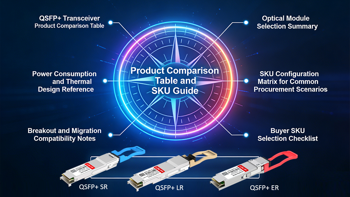
This section provides a structured SKU-level comparison of mainstream 40G QSFP+ transceiver types, enabling rapid technical selection, procurement alignment, and interoperability planning. By comparing optical reach, fiber type, power consumption, DOM/DDM support, and recommended deployment scenarios, buyers can quickly identify the most suitable modules for their network architecture and budget constraints.
-
Data center spine: 40GBASE-SR4
-
Campus aggregation: 40GBASE-LR4
-
Metro transport: 40GBASE-ER4
-
In-rack switching: 40G DAC
QSFP+ Transceiver Product Comparison Table
| Module Type | Standard | Fiber Type | Connector | Typical Reach | Tx Type | Rx Type | Wavelength | Max Power | DOM/DDM | Typical Use Case |
|---|---|---|---|---|---|---|---|---|---|---|
| 40GBASE-SR4 | IEEE 802.3ba | OM3 / OM4 MMF | MPO-12 | 100 m (OM3) 150 m (OM4) |
VCSEL | PIN | 850 nm ×4 | ≤1.5 W | Yes | Data center leaf–spine, short reach |
| 40GBASE-LR4 | IEEE 802.3ba | OS2 SMF | LC duplex | 10 km | DFB | PIN | 1271/1291/1311/1331 nm | ≤4.5 W | Yes | DCI, campus backbone, aggregation |
| 40GBASE-ER4 | IEEE 802.3ba | OS2 SMF | LC duplex | 40 km | EML | APD | 1271–1331 nm | ≤5.0 W | Yes | Metro, carrier transport |
| 40GBASE-ZR4 | Vendor-specific | OS2 SMF | LC duplex | 80 km | EML | APD | 1271–1331 nm | ≤6.0 W | Yes | Long-haul transport |
| 40G DAC (Passive) | MSA | Copper | QSFP+ Direct | ≤5 m | N/A | N/A | Electrical | ≤0.15 W | No | In-rack server–switch |
| 40G DAC (Active) | MSA | Copper | QSFP+ Direct | ≤10 m | N/A | N/A | Electrical | ≤0.5 W | No | Short row interconnect |
| 40G AOC | MSA | MMF | QSFP+ Direct | ≤30 m | VCSEL | PIN | 850 nm | ≤2.0 W | Limited | Data center interconnect |
Optical Module Selection Summary
| Distance Range | Recommended Module |
|---|---|
| ≤150 m | 40GBASE-SR4 |
| ≤2 m – 10 m | Passive / Active DAC |
| ≤30 m | AOC |
| ≤10 km | 40GBASE-LR4 |
| ≤40 km | 40GBASE-ER4 |
| ≤80 km | 40GBASE-ZR4 |
Power Consumption and Thermal Design Reference
| Module | Typical Power | Deployment Consideration |
|---|---|---|
| SR4 | 1.2–1.5 W | Ideal for dense deployments |
| LR4 | 3.5–4.5 W | Moderate cooling required |
| ER4 | 4.5–5.0 W | Strong airflow essential |
| ZR4 | 5.0–6.0 W | Limited switch compatibility |
SKU Configuration Matrix for Common Procurement Scenarios
| Deployment Scenario | Recommended SKU | Key Selection Rationale |
|---|---|---|
| Leaf–Spine Fabric | QSFP+-40G-SR4 | Low cost, high density, low power |
| TOR to Aggregation | QSFP+-40G-LR4 | 10 km reach, duplex LC |
| Campus Backbone | QSFP+-40G-LR4 | SMF infrastructure compatibility |
| Metro Transport | QSFP+-40G-ER4 | Long reach + high stability |
| In-rack Server Links | 40G DAC | Ultra-low latency + low cost |
| Cross-row Interconnect | 40G AOC | Easy routing, EMI immunity |
Breakout and Migration Compatibility Notes
| Host Port | Breakout Mode | Supported |
|---|---|---|
| QSFP+ → 4 × SFP+ | 4 × 10GBASE-SR / LR | Yes |
| QSFP+ → 2 × SFP+ | 2 × 20G (non-standard) | Limited |
| QSFP+ → QSFP28 | 40G → 100G | Not directly |
Engineering note:
QSFP+ SR4 modules can support 4×10G breakout using MPO–LC harness cables, allowing gradual migration from 10G to 40G architectures.
Buyer SKU Selection Checklist
Before placing orders, confirm:
-
✔ Required transmission distance
-
✔ Fiber infrastructure (MMF vs SMF)
-
✔ Port density and thermal capacity
-
✔ Compatibility coding requirement
-
✔ DOM/DDM monitoring needs
-
✔ Breakout capability
7️⃣ Conclusion for 40G QSFP+ Transceivers Procurement
Selecting and purchasing 40G QSFP+ modules is no longer a simple component-buying task — it is a combined engineering validation and strategic procurement process. As network architectures scale toward higher density, lower latency, and multi-vendor interoperability, optics selection becomes a critical factor influencing performance stability, operational risk, and total cost of ownership (TCO).
An effective procurement strategy integrates:
-
Accurate optical and thermal planning,
-
Strict interoperability and lab validation workflows, and
-
Robust commercial safeguards, including warranty terms, RMA mechanisms, and lot traceability controls.
By rigorously testing sample units before volume deployment, insisting on full DOM/DDM transparency and compatibility documentation, and negotiating enterprise-grade service-level protections, organizations can significantly reduce operational risk while achieving optimal network performance and procurement efficiency.
For validated, MSA-compliant 40G QSFP+ transceivers, professional interoperability testing, and enterprise procurement support — including sample evaluation, compatibility validation, and tailored volume quotations — contact:
LINK-PP provides:
-
Full MSA-compliant QSFP+ optics (SR4 / LR4 / ER4 / ZR4 / DAC / AOC)
-
Multi-vendor compatibility validation
-
EEPROM coding customization
-
Enterprise-grade RMA and cross-ship services
-
Long-term supply stability
Request datasheets, compatibility matrices, and free samples to accelerate your network deployment with confidence.
Appendix — Quick Reference
Standards & specs to reference
-
QSFP MSA mechanical/electrical specification (SFF-8436)
-
DOM/DDM memory mapping (SFF-8472)
-
IEEE 802.3 family for 40GBASE standards (802.3ba, and 40GBASE specifics)
Essential fields to include on product pages and POs
-
Exact SKU and part number
-
Connector type (MPO/LC), fiber type, and reach
-
Typical and maximum power consumption
-
DOM support and SFF-8472 compliance
-
Compatibility list (switch models + firmware)
-
Warranty terms and RMA SLA
-
Lot date code and serial ranges