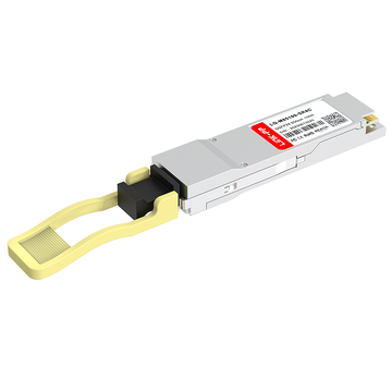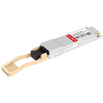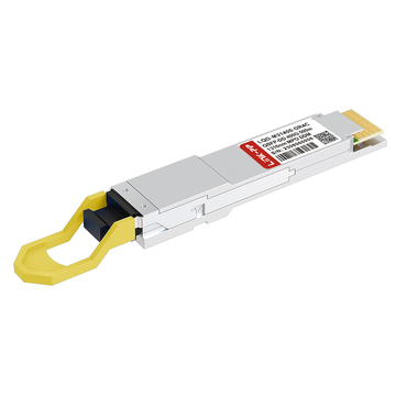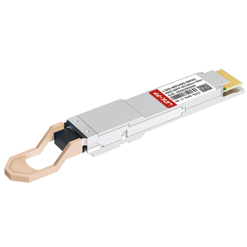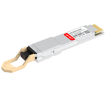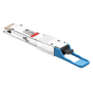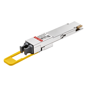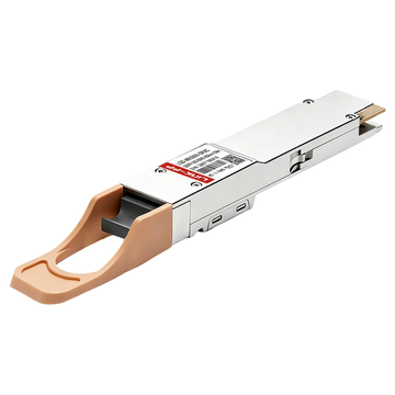
As modern data centers scale to support unprecedented bandwidth demands, how can network operators efficiently maximize port density within limited rack spaces? While traditional LC duplex connections remain highly reliable for standard point-to-point links, high-density environments increasingly require more streamlined cabling pathways. Could integrating an MPO SFP module be the ideal step forward to consolidate multiple fiber strands into a single, compact transceiver footprint?
However, migrating to high-density parallel optics involves more than just swapping out hardware components. How does the internal interface logic of these modules successfully route multiple high-speed data lanes without compromising signal integrity? Furthermore, how can engineers effectively manage the complexities of multi-fiber polarity and alignment to ensure seamless connectivity across the entire network fabric?
↘️ Defining the Core Interface Logic of MPO SFP Modules
The operational efficiency of high-density networks relies heavily on the internal engineering of advanced optical transceivers. Understanding how an MPO SFP module processes signals is essential for designing robust, high-bandwidth data pathways. Unlocking this core interface logic reveals how multiple data streams can coexist seamlessly within a single, compact hardware component.
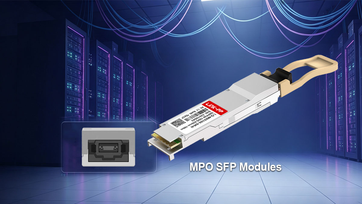
Decoupling Parallel Optics: How MPO SFP Internal Logic Routes Multi-Fiber Lanes
Parallel optics technology fundamentally changes how data travels by splitting a single high-speed data stream across multiple physical fiber strands simultaneously. Inside each MPO SFP module, advanced internal routing logic ensures that these parallel data lanes are decoupled and directed without interfering with one another. This precise orchestration allows the transceiver to maximize bandwidth efficiency while maintaining low latency across short-reach network connections.
To prevent data corruption, the internal architecture isolates each optical lane into dedicated lanes within the multi-fiber connector interface. This systemic decoupling process is vital for supporting high-rate applications that demand simultaneous transmit and receive capabilities. Ultimately, mastering this lane routing logic allows network engineers to fully exploit the high-throughput capabilities of modern parallel optical systems.
Electrical-to-Optical Mapping: Signal Transmission Logic Across 4-Channel & 8-Channel Arrays
The primary function of an MPO SFP transceiver is the seamless conversion of electrical signals from the network switch into optical signals for fiber transmission. This critical electrical-to-optical mapping relies on sophisticated internal arrays that distribute data predictably across 4-channel or 8-channel configurations. The following breakdown illustrates how different channel arrays allocate these signal paths to maintain transmission efficiency.
| Channel Array Type | Electrical Input Configuration | Optical Output Mapping Logic | Primary Application Context |
| 4-Channel Array | 4 independent electrical lanes | Maps to 4 transmit fibers + 4 receive fibers (8 fibers total) | Standard high-density data center links (e.g., 40G/100G SR4) |
| 8-Channel Array | 8 aggregated electrical lanes | Maps to 8 transmit fibers + 8 receive fibers (16 fibers total) | Ultra-high bandwidth aggregation zones (e.g., 400G/800G SR8/DR8) |
As shown above, the choice between 4-channel and 8-channel mapping directly influences how the underlying transceiver architecture utilizes its available fiber strands. This structured mapping logic guarantees that every byte of data entering the hardware is accurately translated into light pulses without any processing delay.
Pinout Architecture and Transceiver Firmware Logic for Tx/Rx Separation
Physical separation of transmit (Tx) and receive (Rx) signals is critical to avoiding destructive network loopbacks and data collisions within dense fiber paths. The hardware pinout architecture of an MPO SFP module assigns rigid, specific positions to each transmission and reception lane inside the physical interface. Simultaneously, intelligent transceiver firmware monitors these assignments in real-time to ensure that data flows exclusively in the correct direction.
This combination of physical pinouts and firmware safeguards allows the system to establish clean bi-directional communication over a single multi-fiber connector. If a mapping anomaly occurs, the firmware logic can immediately flag the error to prevent broader network disruptions. Therefore, the harmony between physical pin design and firmware intelligence forms the backbone of reliable multi-fiber operations.
Multi-Source Agreement (MSA) Logic Standards Governing MPO SFP Form Factors
Interoperability across different networking vendors is made possible by compliance with strict Multi-Source Agreement (MSA) standards. These industry standards define the precise electrical, mechanical, and logical boundaries that every MPO SFP manufacturer must follow. By adhering to MSA guidelines, these compact transceivers can seamlessly operate in any compliant switch port regardless of the brand.
Furthermore, MSA standards govern the communication protocols between the host switch and the transceiver's internal management interface. This logical standardization ensures that digital diagnostics monitoring functions work universally to provide accurate power and temperature readings. Consequently, MSA logic standards provide the foundational predictability required to scale modern open-networking infrastructures safely.
↘️ High-density Cabling Architecture Enabled by MPO SFP Technology
The implementation of advanced optical modules significantly influences the physical design of modern network infrastructure. Leveraging MPO SFP technology allows data centers to transcend the physical limitations of traditional cabling frameworks. This architectural shift enables unprecedented spatial efficiency while fully supporting ultra-high-bandwidth communication.

Optimizing Structured Cabling Footprints Using Multi-Fiber SFP Trunks
Structured cabling footprints must evolve to keep pace with the increasing concentration of high-capacity network switches. Utilizing multi-fiber trunks connected directly to MPO SFP modules allows engineers to consolidate extensive fiber runs into centralized, manageable pathways. This consolidation drastically reduces the physical space required for interconnects, freeing up valuable real estate inside dense server enclosures.
Furthermore, these pre-terminated multi-fiber trunks simplify the initial deployment phase and minimize the potential for human error during installation. By replacing numerous individual cords with a singular, high-capacity trunk cable, data centers can achieve a much cleaner and more organized architecture. Ultimately, this footprint optimization ensures that network environments remain organized, accessible, and easily scalable for future upgrades.
Scaling Rack-to-Rack Density: Transitioning from LC Duplex to MPO Fabrics
As data centers scale out, transitioning from traditional LC duplex connections to unified MPO fabrics becomes a critical operational milestone. While LC connections serve lower-density links exceptionally well, they require significantly more physical port space when aggregating multiple channels. Adopting an MPO SFP infrastructure allows network operators to multiply their port density without expanding the physical footprint of their existing racks.
This architectural transition enables a seamless migration path toward high-density, parallel optical fabrics between adjacent switch racks. By condensing multiple transmit and receive paths into a single interface, operators can maximize the data throughput of every rack unit. Consequently, this migration supports higher computing concentrations while maintaining a highly reliable and structured connection matrix.
Pathways and Spaces: Managing Cable Tray Volume with Compact MPO SFP Runs
Managing physical cable tray volume is a critical factor for maintaining proper airflow and cooling efficiency within crowded data tracks. Traditional overhead pathways can quickly become congested when flooded with hundreds of individual patch cords, risking thermal strain on hardware. Deploying compact MPO SFP cable runs effectively solves this problem by drastically reducing the physical diameter of required cable bundles.
Thinner, highly concentrated ribbon cables require significantly less space in overhead trays and underfloor pathways, allowing cooling air to circulate freely. This reduction in physical cable mass also lightens the structural load on cable management suspension systems throughout the facility. As a result, optimizing these pathways ensures long-term operational safety and efficiency for high-density networking environments.
↘️ Polarity Integration: Aligning MPO SFP Interface Logic with Cabling Systems
Achieving seamless communication across a high-density network requires absolute synchronization between hardware logic and physical cabling. Properly aligning the internal transmission paths of an MPO SFP module with external fiber infrastructure guarantees that data always reaches its intended destination. Managing these multi-fiber channels correctly eliminates the unique routing complexities that typically disrupt parallel optical links.

Understanding Polarity Methods A, B, and C in Multi-Fiber Transmissions
Maintaining correct fiber polarity is essential to ensure that the transmit signal from one hardware port perfectly matches the receive port at the opposite end. Industry standards define three distinct mapping strategies — Methods A, B, and C — to manage these complex multi-fiber paths across structured cabling networks.
The following matrix compares how each of these standard structural methods manipulates the internal fiber orientation to preserve the core transmission logic of the MPO SFP transceiver.
| Polarity Method | Cable Type Configuration | Key Operational Feature | Transceiver Logic Alignment |
| Method A | Straight-through (Key Up to Key Down) | Pin 1 maps directly to Pin 1 across the link | Requires a specific flipped patch cord at one end to match Tx/Rx logic. |
| Method B | Flipped (Key Up to Key Up) | Pin 1 maps to Pin 12, reversing the entire fiber array | Allows identical patch cords to be used at both ends of the network. |
| Method C | Pair-flipped (Key Up to Key Down) | Adjacent fiber pairs are crossed sequentially | Automatically corrects Tx/Rx logic assignments for duplex-based segments. |
Matching Transceiver Tx/Rx Pin Assignments with the Right Patch Cables
The internal design of an MPO SFP module features a highly specific layout where individual pins are strictly dedicated to either transmitting or receiving data. Connecting these modules successfully requires selecting external patch cables that complement these exact hardware pin assignments.
If the external cabling fails to match the transceiver's configuration, the data streams will conflict and cause complete link loss. Using specialized parallel optics patch cords allows the system to bridge these physical lane gaps securely and efficiently.
Pinning Configurations: Navigating Male vs. Female MPO SFP Interfaces
Physical alignment in multi-fiber connections relies entirely on a precise pinning configuration system consisting of male and female connectors. An MPO SFP interface typically features a specific gendered configuration that must be carefully matched with the corresponding cable connector.
Male connectors utilize small alignment pins, whereas female connectors feature matching guide holes designed to accept them seamlessly. Forcing mismatched genders together will permanently destroy the delicate optical fiber faces and cause irreversible physical hardware damage.
Preventing Signal Crossover Failures in Complex Cross-Connect Networks
In vast, multi-stage cross-connect environments, the risk of experiencing a catastrophic signal crossover failure increases dramatically with every added connection point. When multiple MPO SFP modules are linked across intricate patch panels, tracking individual data lanes manually becomes incredibly challenging.
A single incorrect patch configuration can easily route a transmit line directly into another transmit line, instantly dropping the connection. Preventing these costly logic failures requires implementing strict, standardized documentation alongside rigorous physical verification testing during deployment.
↘️ Signal Integrity Challenges in MPO SFP High-density Cabling
As data transmission speeds accelerate within modern network architectures, maintaining pristine signal integrity poses a formidable engineering challenge. Deploying an MPO SFP parallel optical system introduces complex physical and electromagnetic phenomena that can rapidly degrade high-frequency data streams if left unmanaged. Minimizing these signal impairments is essential for preserving the low bit-error rates required by enterprise-grade switching fabrics.
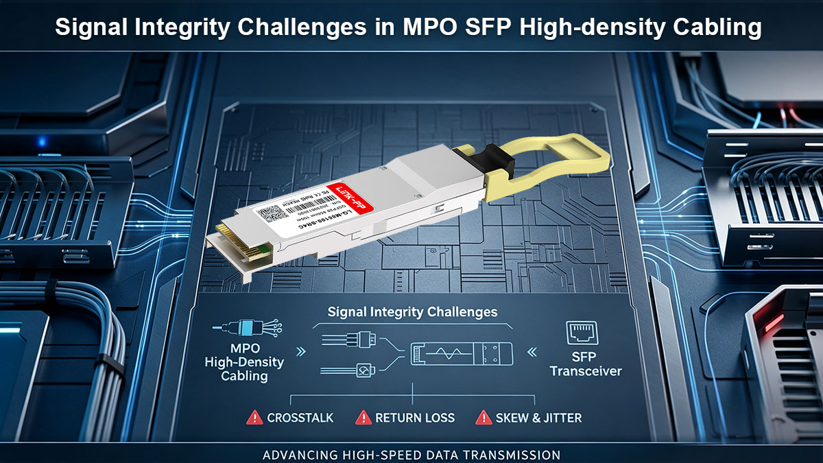
Managing Optical Insertion Loss Across Multi-Fiber Connections
Optical insertion loss represents the cumulative attenuation of signal power as light travels through physical connection points, splices, and glass mediums. Within an MPO SFP interface, twelve or twenty-four distinct fiber strands are mated simultaneously within a single microscopic connector footprint, making the link highly sensitive to mechanical tolerances.
Even a microscopic layer of dust or a nanometer-scale lateral misalignment can cause severe, uneven power drops across adjacent channels. This uneven attenuation destabilizes the receiver's calibration, forcing network engineers to implement ultra-low-loss components and strict physical cleaning regimens to maintain the integrity of the optical path.
Mitigating Crosstalk and Electromagnetic Interference in Tight Bundles
High-density network designs require grouping numerous active communication channels into exceptionally tight physical bundles over extended distances. Inside the compact architecture of an MPO SFP transceiver, this extreme proximity creates a high risk of electromagnetic interference (EMI) between adjacent high-speed electrical traces.
Simultaneously, near-end optical crosstalk can occur within the fiber ribbon cable if stray light photons bleed through the cladding into neighboring glass cores. Mitigating these multi-channel interferences demands advanced internal shielding, optimized circuit trace layouts, and precision-engineered fiber geometries that cleanly isolate each parallel data stream.
The Impact of Return Loss (ORL) on High-Speed Parallel Interface Logic
Optical Return Loss (ORL) measures the ratio of launched optical power to the total amount of light reflected backward toward the transmitter by material imperfections and air gaps. High back-reflections severely disrupt the internal laser diode stability of an MPO SFP module, corrupting the delicate balance of its parallel processing architecture.
Excessive back-reflections alter the system's performance in the following specific ways:
- Bit Error Rates Rise: Reflected wave pulses collide with oncoming light streams to distort incoming data edges.
- Laser Instability: Returned photons induce optical phase noise and erratic wavelength shifts within the transmitter.
- Firmware Calibrations Fail: Reflected light tricks the internal digital diagnostics monitoring software into reading false power levels.
- Logic Sync Losses: Timing jitter increases rapidly until the internal logic fails to align the parallel data lanes.
Maintaining Tight Power Budgets in Multi-Stage High-Density Links
Every high-speed parallel optical channel operates within a rigid link power budget that dictates the maximum allowable decibel loss between the transmitter and the receiver. An MPO SFP deployment must share this limited power budget across a complex matrix of patch panels, trunk splices, and cross-connect systems.
If the combined optical loss of these physical stages exceeds the pre-engineered budget threshold, the receiving photodiode will fail to distinguish valid light pulses from background noise. Consequently, maintaining a strict power budget through precise loss-forward planning is vital to preventing sudden packet drops and system-wide logic failures.
↘️ Deployment Best Practices for MPO SFP High-density Cabling

Executing a flawless installation protocol is just as critical as selecting the right hardware components for your network. Adopting industry-standard deployment methodologies protects fragile multi-fiber connections from physical strain and environmental contamination. These operational strategies ensure that your infrastructure achieves maximum data throughput and long-term mechanical reliability.
Proper Routing Protocols for Multi-Fiber Trunks in Server Racks
Implementing structured routing protocols inside server enclosures prevents heavy fiber trunks from blocking vital equipment cooling pathways. Properly managing these trunk pathways guarantees that airflow remains unobstructed while allowing technicians easy access to the back of the hardware blades.
Adhering to the following structural routing protocols helps maintain a highly stable server rack environment:
- Separate Data and Power: Keep optical trunks far away from heavy electrical cabling.
- Utilize Vertical Managers: Route large multi-fiber trunks along the sides of the rack.
- Avoid Overhead Hanging: Never let unsupported trunk cables hang directly above active switches.
- Secure with Hook-and-Loop: Use soft fabric ties rather than harsh plastic zip ties.
Bend Radius and Tension Management for High-Density Ribbon Cables
High-density ribbon cables house multiple sensitive glass cores within a single, flattened outer jacket. Exceeding the manufacturer's specified bend radius or applying excessive pulling tension can fracture the inner fibers or induce severe microbending signal loss.
Careful physical handling of ribbon cables involves monitoring several key environmental installation factors:
- Check Minimum Bend Radius: Maintain a curve radius of at least twenty times the cable diameter during pulling.
- Limit Pulling Force: Never exceed the maximum tensile load limits specified by the manufacturer.
- Use Proper Mandrels: Wrap cables around rounded support wheels at sharp pathway corners.
- Monitor Slack Loops: Leave designated, stress-free slack loops inside overhead trays for future adjustments.
Optimizing Patch Panel Distribution for Seamless SFP Module Insertion
Optimizing your patch panel layout streamlines the transition from dense trunk lines to individual active switch ports. Strategic distribution design ensures that patch cords run cleanly to each MPO SFP transceiver without creating heavy, tangled clusters in front of the switch face.
Structuring your distribution panels correctly maximizes physical hardware accessibility through the following design choices:
- Match Port Densities: Align patch panel modular configurations with the underlying switch port layout.
- Stagger Patch Cord Lengths: Use precise, varying cable lengths to eliminate excess slack accumulation.
- Angle the Enclosures: Implement angled patch panels to guide fiber patch cords naturally toward side managers.
- Clear the Insertion Path: Ensure that no overlapping cables block direct finger access to the module latches.
Labeling and Documenting Intricate Multi-Fiber Interface Logic Mapping
Comprehensive labeling and digital documentation form the foundation of manageable high-density networking environments. Because an MPO SFP deployment aggregates multiple discrete data lanes into unified physical connections, a single unlabeled port can lead to massive troubleshooting confusion later on.
Creating a dependable identification system requires tracking specific connectivity details across your network documentation:
- Use Color-Coded Labels: Assign distinct colors to represent different polarity methods or network tiers.
- ID Every Strand: Document the exact path of each sub-channel lane inside the multi-fiber array.
- Tag Both Ends: Place matching, highly visible identification tags on both ends of every trunk cable.
- Update Digital Layouts: Log all active pinout logic maps into your central infrastructure software immediately.
↘️ Troubleshooting MPO SFP Interface Logic and Connectivity Issues
Even with meticulous deployment practices, complex parallel optical networks can occasionally encounter link failures or performance degradation. Rapidly isolating faults within a multi-fiber system requires a systematic approach that separates hardware logic errors from physical layer damage. Utilizing the right combination of diagnostic software and specialized testing equipment ensures that link uptime is restored with minimal disruption to data center traffic.
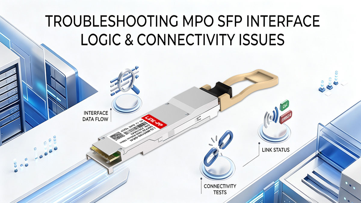
Diagnosing Channel Misalignment and Polarity Mismatches via Software
Network operators can leverage the host switch's operating system to identify underlying channel communication errors without pulling physical cables. Accessing the digital diagnostics monitoring (DDM) interface of the MPO SFP transceiver allows real-time visibility into the performance of individual parallel lanes.
When systemic polarity mismatches occur, such as mixing Type-A and Type-B patch cables, the software will typically report a total loss of signal (LOS) across all receiving channels simultaneously. Conversely, uneven optical power distribution across the array usually indicates localized physical impairments like a macrobend or individual fiber defects rather than a routing logic error.
Using MPO Power Meters to Isolate Physical Layer Cabling Faults
When software diagnostics point to a physical layer issue, deploying a dedicated MPO power meter is the most efficient way to pinpoint the exact failure location. Unlike standard single-fiber meters, these specialized instruments test all parallel optical strands simultaneously to provide an immediate snapshot of the entire array.
Connecting the meter to the suspected trunk segment reveals exactly which fiber lanes are suffering from excessive insertion loss. This precise physical measurement allows technicians to isolate faulty patch links, dirty couplers, or crushed ribbon cables across the high-density infrastructure.
Identifying Transceiver Firmware Errors vs. Fiber Attenuation Problems
Distinguishing between internal transceiver failures and external optical path degradation is critical when an MPO SFP link fails to establish. In many troubleshooting scenarios, the switch DDM may show that incoming optical power has successfully reached the port, yet the link remains down.
This specific symptom indicates that while the physical light path is intact, the link cannot mature due to clock and data recovery (CDR) loss-of-lock, severe signal integrity distortion, or protocol negotiation failures. Cross-referencing these active hardware error states with physical layer attenuation tests allows engineers to determine whether to swap the module or recertify the fiber run.
Cleaning Protocols for Multi-Fiber End-Faces to Restore Interface Signal Logic
Contamination remains the leading cause of optical signal degradation and intermittent logic failures in high-density multi-fiber networks. Because an MPO SFP module relies on a microscopic connection interface with a tight 250-micron core pitch, even localized debris can severely attenuate specific data lanes.
Restoring performance requires following a strict "inspect, clean, inspect" protocol using specialized dry-cloth click cleaners designed specifically for multi-fiber arrays. Ensuring that the fiber end-faces are pristine allows the parallel interface logic to re-synchronize and maintain maximum transmission speeds without packet loss.
↘️ Key Takeaways on Integrating MPO SFP Interface Logic into Modern Networks
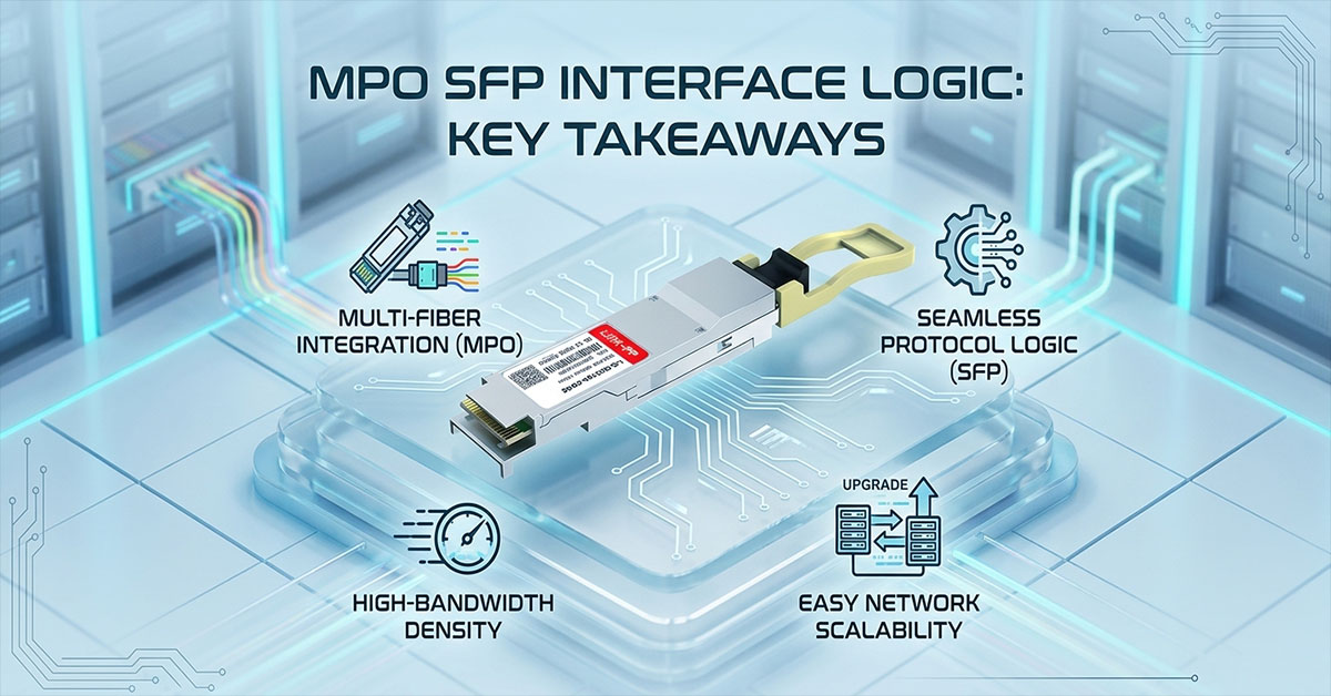
Successfully integrating parallel optical technology requires a balanced understanding of both internal transceiver intelligence and physical cable management. By mastering the core interface logic of the MPO SFP module, network operators can confidently overcome density constraints without compromising signal integrity or link stability. Adhering to standardized polarity methods, maintaining tight link power budgets, and practicing rigorous troubleshooting protocols will ensure your enterprise fabric remains highly resilient as data demands scale.
Building a dependable high-density infrastructure ultimately relies on deploying high-quality components that strictly adhere to these demanding technical standards. For those looking to optimize their parallel optical links, the LINK-PP Official Store offers a robust portfolio of MSA-compliant MPO SFP transceivers engineered for seamless hardware interoperability and superior signal integrity. Choosing reliable, precision-tested modules allows you to safeguard your network against performance drops and future-proof your data center for next-generation bandwidth demands.