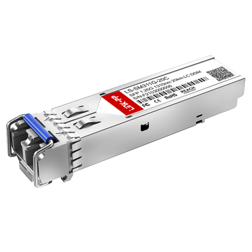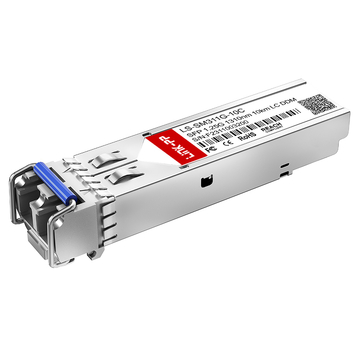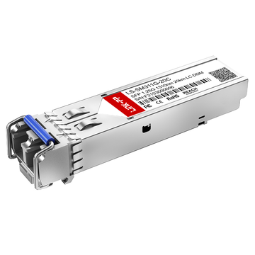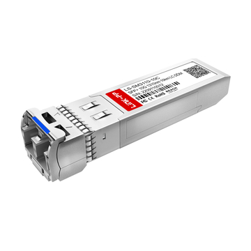
As enterprise networks, cloud infrastructure, industrial automation systems, and telecom environments continue to expand, long-distance fiber connectivity has become a critical part of modern network design. Organizations increasingly rely on optical transmission solutions that can deliver stable performance, lower latency, and scalable bandwidth across campus networks, data centers, and distributed business locations.
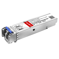
Among the most widely deployed solutions, SFP LC Single Mode transceivers are commonly used for reliable long-range fiber communication. These optical modules combine compact SFP form factors with LC fiber interfaces and single mode transmission technology, making them suitable for applications ranging from Gigabit Ethernet to high-speed 10G and 25G networking environments.
However, choosing the right SFP LC Single Mode module is not always straightforward. Different transmission distances, wavelengths, compatibility requirements, fiber types, temperature ranges, and switch platforms can significantly affect deployment success. Selecting an unsuitable module may lead to interoperability issues, unstable links, excessive power consumption, or unnecessary infrastructure costs.
In addition, modern network environments often require balancing multiple considerations at the same time, including:
- Long-distance transmission reliability
- Compatibility with switches and routers
- Future bandwidth scalability
- Fiber infrastructure efficiency
- Stable thermal and operational performance
- Cost-effective network expansion
Because of these factors, network engineers and IT decision-makers need a clear understanding of how different SFP LC Single Mode optics work and which specifications matter most in real deployment scenarios.
This article will explain how to choose the right SFP LC Single Mode transceiver based on transmission requirements, compatibility, fiber infrastructure, environmental conditions, and long-term network planning. It will also compare different module types, highlight common selection mistakes, and provide practical recommendations for stable optical network deployment.
✳️ What Is an SFP LC Single Mode Transceiver?
An SFP LC Single Mode transceiver is a compact optical module designed for long-distance fiber communication in Ethernet and telecom networks. It uses an LC fiber connector and single mode optical fiber to transmit data over significantly longer distances than multimode solutions, making it widely used in enterprise backbones, data centers, telecom infrastructure, and industrial networking environments.
These transceivers are commonly deployed in switches, routers, firewalls, media converters, and optical transport equipment where stable and efficient fiber connectivity is required.
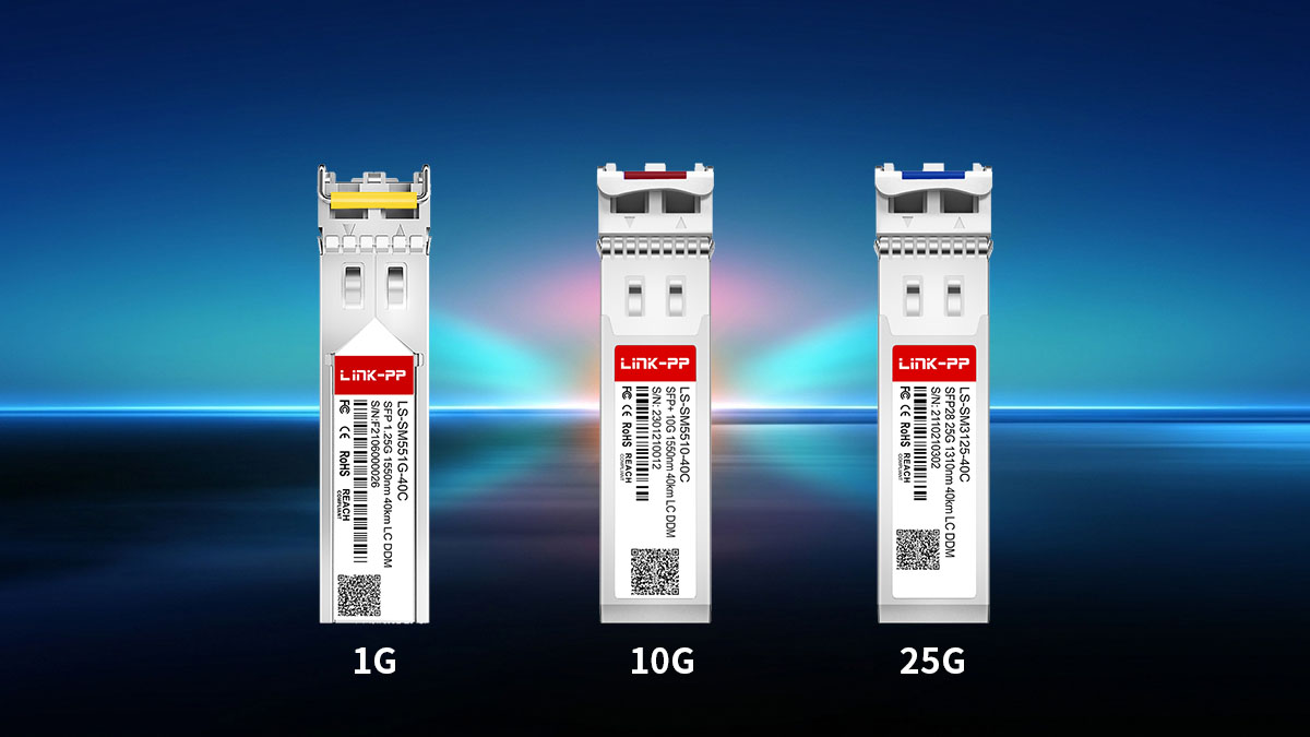
Definition and Core Function
An SFP LC Single Mode module primarily enables optical signal transmission between network devices over single mode fiber cabling. Its compact size and hot-swappable design make it a flexible solution for scalable network deployments.
Several core technologies work together inside these optical transceivers:
- SFP (Small Form-factor Pluggable) defines the compact modular interface standard
- LC connectors provide high-density fiber connectivity
- Single mode fiber enables long-distance transmission with low signal attenuation
- Optical lasers convert electrical signals into light signals for transmission
These modules are typically installed into SFP ports on networking equipment to establish fiber uplinks between buildings, server rooms, telecom cabinets, or remote infrastructure locations.
In most enterprise and carrier deployments, SFP LC Single Mode transceivers are selected because they provide:
- Longer transmission distance than multimode optics
- Better signal stability over extended fiber runs
- Lower attenuation for high-speed communication
- Flexible scalability across different network architectures
Key Technical Characteristics
The performance of an SFP LC Single Mode transceiver depends on several technical specifications, including transmission speed, wavelength, connector type, and supported distance. These parameters directly affect compatibility and deployment suitability.
The following table summarizes the most common technical characteristics found in single mode SFP optics:
| Parameter | Common Specifications |
|---|---|
| Connector Type | Duplex LC |
| Fiber Type | OS1 / OS2 Single Mode Fiber |
| Transmission Speed | 1Gbps, 10Gbps, 25Gbps |
| Typical Wavelength | 1310nm, 1490nm, 1550nm |
| Transmission Distance | 10km, 20km, 40km, 80km+ |
| Installation Type | Hot-swappable |
| Optical Technology | Standard Duplex, BiDi, CWDM, DWDM |
Among these specifications, transmission wavelength and optical budget are especially important because they influence achievable distance and signal quality.
Common Application Scenarios
SFP LC Single Mode transceivers are widely used in environments that require stable long-distance fiber connectivity and scalable bandwidth performance. Their flexibility allows them to support both traditional enterprise infrastructure and modern high-density networking architectures.
Common deployment scenarios include:
- Enterprise campus backbone connections
- Inter-building fiber links
- Data center aggregation networks
- Telecom access and metro networks
- Industrial Ethernet environments
- Security surveillance transmission systems
- Smart city infrastructure
- ISP and broadband distribution networks
Different applications usually require different optical specifications depending on bandwidth and transmission distance.
✳️ Understanding the Different Types of SFP LC Single Mode Modules
SFP LC Single Mode transceivers are available in several different categories, and each type is designed for specific network speeds, transmission distances, and optical architectures. Understanding these differences is essential because selecting the wrong module can lead to compatibility issues, unstable fiber links, or unnecessary infrastructure limitations.
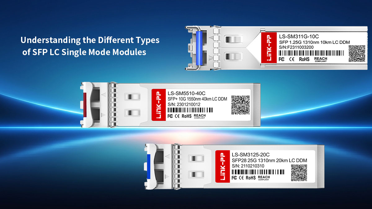
In most enterprise and telecom environments, SFP LC Single Mode modules are commonly categorized by:
- Transmission speed
- Supported transmission distance
- Optical transmission technology
Each classification affects network scalability, fiber utilization, and deployment efficiency in different ways.
By Transmission Speed
Transmission speed is one of the first factors that determines which SFP LC Single Mode module should be deployed. Different Ethernet generations require different optical standards, and matching module speed with switch port capability is critical for stable operation.
The table below outlines the most common speed categories used in modern optical networking environments.
| Module Type | Data Rate | Typical Deployment |
|---|---|---|
| Fast Ethernet SFP | 100Mbps | Legacy industrial networks |
| Gigabit SFP | 1Gbps | Enterprise access and campus networks |
| SFP+ | 10Gbps | Data centers and aggregation layers |
| SFP28 | 25Gbps | Cloud and hyperscale infrastructure |
Different speed classes serve different operational goals depending on network bandwidth requirements and future upgrade planning.
Fast Ethernet SFP Modules
Fast Ethernet single mode SFP modules (100M SFP) are primarily used in older network infrastructures where 100Mbps bandwidth remains sufficient for operational requirements.
These modules are commonly found in:
- Industrial automation systems
- Legacy telecom equipment
- Transportation infrastructure
- Older surveillance deployments
Although they are less common in modern enterprise networks, Fast Ethernet optics still remain important in long-lifecycle industrial environments.
Gigabit SFP Modules
Gigabit SFP LC Single Mode modules (1G SFP) are among the most widely deployed optical transceivers worldwide. They provide reliable 1Gbps transmission over single mode fiber while maintaining relatively low deployment complexity.
Typical applications include:
- Enterprise backbone uplinks
- Fiber access networks
- Campus network infrastructure
- SMB fiber deployments
- ISP distribution networks
Most standard Gigabit single mode optics support transmission distances of up to 10km using 1310nm wavelengths.
10G SFP+ Modules
10G SFP+ single mode modules are designed for higher-bandwidth environments that require faster data transmission and lower latency.
These modules are commonly deployed in:
- Data center aggregation layers
- Cloud computing environments
- High-density enterprise switching
- Storage area networks
- Metro Ethernet infrastructure
Compared with 1G optics, 10G SFP+ modules significantly improve bandwidth scalability for growing network traffic demands.
25G SFP28 Modules
SFP28 single mode optics support 25Gbps transmission and are increasingly used in modern cloud and AI-driven infrastructure.
Their key advantages include:
- Higher port density
- Better bandwidth efficiency
- Improved scalability
- Lower power consumption per gigabit
25G SFP28 deployments are especially common in spine-leaf architectures and hyperscale data centers.
By Transmission Distance
SFP LC Single Mode modules are also differentiated by their supported optical transmission distance. The required transmission range directly affects wavelength selection, optical power output, and overall module design.
The following table summarizes common transmission distance categories.
| Distance Category | Typical Reach | Common Wavelength |
|---|---|---|
| Standard Range | 10km | 1310nm |
| Medium Range | 20km to 40km | 1310nm / 1550nm |
| Long Range | 60km to 80km | 1550nm |
| Extended Range | 100km+ | DWDM wavelengths |
Selecting the correct transmission distance is important because over-specifying or under-specifying optics can negatively affect network efficiency and signal performance.
10km Optical Modules
10km single mode SFP and SFP+ transceivers are widely adopted because they provide a strong balance between performance, compatibility, and deployment flexibility.
These optics are popular due to:
- Broad vendor support
- Stable long-distance transmission
- Simple deployment requirements
- Strong compatibility with OS2 fiber
For many organizations, 10km optics are the default choice for standard fiber networking projects.
20km to 40km Modules
Medium-range optical modules support longer fiber links used in metropolitan and distributed network architectures.
These modules are often selected for:
- Multi-campus connectivity
- Telecom aggregation
- Remote branch connections
- Industrial fiber deployments
Because transmission distances increase, optical attenuation and signal budget calculations become more important.
Long-Haul and Extended-Distance Modules
Long-haul SFP LC Single Mode optics are designed for carrier-grade infrastructure and large-scale optical transport networks.
Common deployment environments include:
- Telecom backbone infrastructure
- Regional fiber transport systems
- Metropolitan optical rings
- Long-distance industrial networking
These modules typically use higher optical power levels and may require more advanced network planning.
By Optical Technology
Modern SFP LC Single Mode modules use different optical transmission technologies to optimize fiber efficiency and network scalability. Each technology is designed for specific infrastructure requirements and deployment strategies.
The most common optical technologies include:
- Standard duplex optics
- BiDi optics
- CWDM transceivers
- DWDM transceivers
Understanding how these technologies differ helps organizations maximize existing fiber resources while supporting future expansion.
Standard Duplex Optics
Standard duplex SFP LC Single Mode modules use two fiber strands:
- One strand for transmitting data
- One strand for receiving data
These optics are widely used because they offer:
- Simple installation
- Strong interoperability
- Stable optical performance
- Easier troubleshooting
Duplex LC modules remain the most common choice in enterprise networking environments.
BiDi Single Fiber Modules
BiDi (Bidirectional) optics allow both transmission and reception over a single fiber strand by using different wavelengths in each direction.
Their advantages include:
- Reduced fiber consumption
- Lower infrastructure requirements
- Improved cable utilization
- Simplified fiber expansion
BiDi modules are especially valuable in environments with limited available fiber resources.
CWDM Modules
CWDM (Coarse Wavelength Division Multiplexing) modules support multiple optical channels over the same fiber pair using different wavelengths.
CWDM technology is commonly used for:
- Enterprise backbone expansion
- Metro access networks
- Fiber optimization projects
- Medium-density optical transport
This approach allows organizations to increase network capacity without deploying additional fiber cabling.
DWDM Modules
DWDM (Dense Wavelength Division Multiplexing) modules provide higher wavelength density and much larger transmission capacity than CWDM systems.
DWDM optics are typically used in:
- Carrier-grade transport networks
- Long-haul telecom systems
- Hyperscale data center interconnects
- High-capacity metropolitan infrastructure
Although DWDM deployments are more complex, they provide exceptional scalability for bandwidth-intensive networking environments.
In summary: Understanding these different SFP LC Single Mode module types creates a stronger foundation for evaluating compatibility, transmission requirements, and long-term network scalability before deployment decisions are made.
✳️ Key Factors to Consider When Choosing an SFP LC Single Mode Module
Choosing the right SFP LC Single Mode module requires more than simply matching transmission speed. Network stability, interoperability, optical performance, and long-term scalability all depend on selecting optics that properly align with the deployment environment and infrastructure requirements.
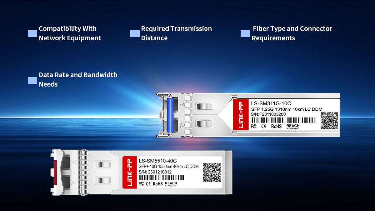
A well-matched optical module helps ensure:
- Stable long-distance transmission
- Reliable switch compatibility
- Efficient fiber utilization
- Lower operational risk
- Better scalability for future upgrades
Before deployment, several technical and operational factors should be carefully evaluated.
Compatibility With Network Equipment
Compatibility is one of the most important considerations when selecting an SFP LC Single Mode transceiver. Even if two modules share similar specifications, differences in firmware coding or hardware validation may affect interoperability with switches, routers, or firewalls.
Switch and Router Compatibility
Different network vendors may implement proprietary validation mechanisms for optical modules. As a result, not every SFP LC Single Mode transceiver will operate identically across all platforms.
Common compatibility-sensitive platforms include:
- Enterprise switches
- Carrier routers
- Security appliances
- Industrial Ethernet systems
- Data center aggregation equipment
Checking platform compatibility lists before installation can significantly reduce deployment risk.
Vendor Coding Considerations
Many network devices rely on EEPROM coding to identify supported optical transceivers. Proper vendor coding helps ensure the module is recognized correctly by the host system.
Common coding options include:
- Cisco-compatible coding
- Juniper-compatible coding
- Arista-compatible coding
- HPE-compatible coding
- Multi-vendor universal coding
Incorrect coding may prevent modules from functioning properly even when hardware specifications match.
MSA Compliance
MSA (Multi-Source Agreement) compliance improves interoperability across networking ecosystems by standardizing module specifications.
MSA-compliant modules typically provide:
- Better cross-platform compatibility
- Easier deployment flexibility
- Reduced vendor dependency
- More predictable operational behavior
In multi-vendor network environments, MSA compliance becomes especially important.
Interoperability Challenges
Even compatible optics can experience interoperability issues under certain conditions.
Typical challenges include:
- Firmware mismatches
- Optical power imbalance
- Unsupported diagnostics
- Link training inconsistencies
- Thermal instability
Performing validation tests before large-scale deployment helps reduce these risks.
Required Transmission Distance
The transmission distance of an SFP LC Single Mode module must align with the actual fiber link requirements. Choosing optics with insufficient reach can cause signal degradation, while excessive optical power may create unnecessary complexity in shorter deployments.
Matching Module Distance With Actual Deployment
The selected optical module should closely match the real deployment distance instead of relying solely on maximum supported range.
Accurate matching helps achieve:
- Stable optical signal levels
- Lower error rates
- Reduced signal reflection
- Better long-term reliability
Over-specification may increase deployment cost without improving actual performance.
Impact of Fiber Attenuation
Fiber attenuation increases over longer distances and can weaken optical signals if not properly managed.
Several factors affect attenuation:
- Fiber quality
- Connector cleanliness
- Splice quality
- Wavelength selection
- Environmental conditions
Lower attenuation is one of the primary advantages of single mode fiber infrastructure.
Fiber Type and Connector Requirements
SFP LC Single Mode modules are designed specifically for single mode fiber environments, but differences in fiber specifications and connector structures still affect deployment reliability.
OS1 vs OS2 Fiber Compatibility
Single mode fiber is generally categorized into OS1 and OS2 standards.
The following table compares their typical characteristics.
| Fiber Type | Typical Environment | Distance Capability |
|---|---|---|
| OS1 | Indoor enterprise deployments | Short to medium distance |
| OS2 | Outdoor and long-distance networks | Extended transmission range |
OS2 fiber is more commonly used in modern long-distance single mode deployments because of its lower attenuation characteristics.
Duplex LC vs Simplex LC
Connector structure depends on the optical technology used by the transceiver.
Common configurations include:
- Duplex LC for standard two-fiber transmission
- Simplex LC for BiDi single-fiber deployments
Choosing the correct connector type is essential for maintaining proper optical communication.
Patch Cable Considerations
Patch cable quality directly affects optical signal stability.
Important considerations include:
- Connector polishing quality
- Bend radius management
- Insertion loss performance
- Cable jacket durability
- Fiber cleanliness
High-quality patch cabling improves long-term optical reliability and reduces troubleshooting complexity.
Data Rate and Bandwidth Needs
Bandwidth demand continues to increase across enterprise, cloud, and AI-driven infrastructure. Selecting optics that support both current and future traffic requirements helps reduce future upgrade costs.
Current Bandwidth Requirements
The selected module should support existing application traffic without creating bottlenecks.
Typical bandwidth-intensive applications include:
- Cloud computing
- Video surveillance
- Data replication
- Virtual desktop infrastructure
- AI training environments
Bandwidth shortages can quickly reduce overall network efficiency.
Future Scalability Planning
Planning for future growth helps avoid repeated infrastructure replacement.
Scalability considerations include:
- Higher port density requirements
- Future Ethernet migration
- Increased storage traffic
- Expanding remote connectivity
- Data center modernization
Many organizations now deploy other high-speed transceivers proactively to simplify future upgrades.
Matching Port Speed With Module Capability
The optical module speed must match the host port capability to ensure stable operation.
Improper speed matching may result in:
- Port negotiation failure
- Link instability
- Reduced throughput
- Unsupported configuration errors
Verifying speed compatibility before deployment helps prevent operational disruptions.
✳️ How to Evaluate Compatibility and Interoperability
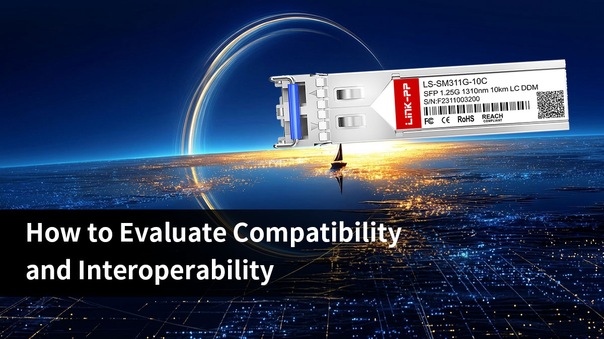
Evaluating compatibility and interoperability is essential when deploying an SFP LC Single Mode module in real network environments. Even if optical parameters such as speed, wavelength, and distance are identical, the module may still fail to operate correctly due to vendor restrictions, firmware validation rules, or platform-specific requirements.
OEM-Coded vs Multi-Vendor Compatible Modules
Understanding the difference between OEM-coded and multi-vendor compatible modules is the foundation of interoperability evaluation. Although both types may share the same optical specifications, their behavior inside network devices can vary significantly.
Differences Between Original and Compatible Optics
Original (OEM-coded) and compatible optics mainly differ in how they are recognized and validated by networking equipment.
Key differences include:
- OEM-coded modules are tied to a specific vendor ecosystem
- Compatible modules use standardized or universal coding approaches
- OEM optics often undergo stricter authentication checks
- Compatible optics prioritize cross-platform adaptability
In practice, both types can deliver similar optical performance, but their deployment flexibility differs depending on network architecture requirements.
Advantages of Interoperability Flexibility
Interoperability flexibility becomes increasingly important in modern multi-vendor networks where equipment from different manufacturers must work together.
Key advantages include:
- Easier integration across different network brands
- More flexible hardware sourcing and replacement options
- Reduced dependency on a single vendor ecosystem
- Simplified expansion in heterogeneous environments
This flexibility is particularly valuable in large-scale enterprise and data center networks where infrastructure diversity is common.
Common Misconceptions About Compatibility
Compatibility is often misunderstood as being determined only by basic optical specifications such as speed and wavelength. In reality, interoperability depends on multiple layers of system validation.
Common misconceptions include:
- Assuming identical specifications guarantee full compatibility
- Believing all SFP transceivers behave the same across vendors
- Ignoring firmware-level validation requirements
- Overlooking diagnostic feature limitations across platforms
A correct evaluation requires both physical specification matching and system-level verification.
Firmware and Platform Validation
Firmware and platform validation plays a critical role in determining whether an SFP LC Single Mode module will function correctly in a specific network device. Even when hardware specifications match, firmware rules may still restrict or modify module behavior.
Importance of Testing With Target Hardware
Testing optical modules directly on the intended hardware is one of the most reliable ways to confirm compatibility.
Key outcomes of hardware testing include:
- Verifying whether the module is correctly recognized
- Checking link stability under real traffic conditions
- Confirming optical power levels and signal quality
- Ensuring diagnostic features operate as expected
Without hardware validation, compatibility issues may only appear after deployment, increasing operational risk.
Vendor Lock-In Considerations
Some networking platforms apply strict vendor lock-in mechanisms that limit the use of non-approved optical modules. These restrictions can affect both functionality and flexibility.
Typical vendor lock-in behaviors include:
- Blocking unapproved transceivers
- Displaying persistent compatibility warnings
- Disabling certain monitoring features
- Restricting firmware-level module recognition
Understanding these constraints is important when designing multi-vendor or long-term scalable networks.
Diagnostic Monitoring Support
Diagnostic monitoring, often implemented through Digital Diagnostic Monitoring (DDM), provides real-time visibility into optical performance. However, support levels may vary depending on both the module and the platform.
Common variations include:
- Full support for temperature, power, and voltage monitoring
- Partial support with limited parameter visibility
- No diagnostic data exposure on some platforms
Incomplete monitoring reduces visibility into network health and can make troubleshooting more difficult over time.
Typical Compatibility Issues
Even when modules are correctly selected and installed, compatibility and interoperability issues may still occur due to firmware behavior, coding mismatch, or optical imbalance.
These issues typically appear during initialization or under sustained network load.
Port Recognition Failures
Port recognition failures occur when the network device cannot properly identify the inserted optical module.
Typical causes include:
- Incorrect EEPROM coding
- Strict vendor identification rules
- Firmware version limitations
- Corrupted module identification data
In many cases, firmware updates or re-coded modules can resolve recognition issues.
Unsupported Transceiver Warnings
Some devices generate warnings when detecting non-approved or unfamiliar modules. These warnings may not always stop operation but indicate limited support.
Common impacts include:
- Restricted monitoring capabilities
- System log alerts or warnings
- Reduced diagnostic visibility
- Potential long-term operational uncertainty
These warnings should be carefully evaluated in production environments.
Signal Instability Problems
Signal instability can occur even when the module is recognized and operational. It is often related to optical or environmental factors rather than basic compatibility.
Typical symptoms include:
- Intermittent link disconnections
- Packet loss under high traffic load
- Fluctuating optical power levels
- Increased bit error rates
Such issues are often caused by optical budget mismatch, fiber quality problems, or thermal variations.
Troubleshooting Approaches
A structured troubleshooting process helps isolate the root cause of compatibility issues more efficiently.
Common troubleshooting steps include:
- Verifying firmware compatibility on the host device
- Checking EEPROM coding information
- Cleaning LC connectors and inspecting fiber quality
- Measuring optical power levels on both ends
- Replacing patch cables for validation testing
Systematic testing helps quickly distinguish between optical, firmware, and environmental causes of instability.
✳️ Comparing SFP LC Single Mode and Other Optical Module Types
Understanding how SFP LC Single Mode modules compare with other optical module types is essential for selecting the right solution in different network environments. Although they may appear similar in form factor or connector type, differences in fiber mode, transmission distance, and deployment complexity can significantly impact performance and infrastructure design.
A clear comparison helps network planners optimize cost, scalability, and long-term operational stability.
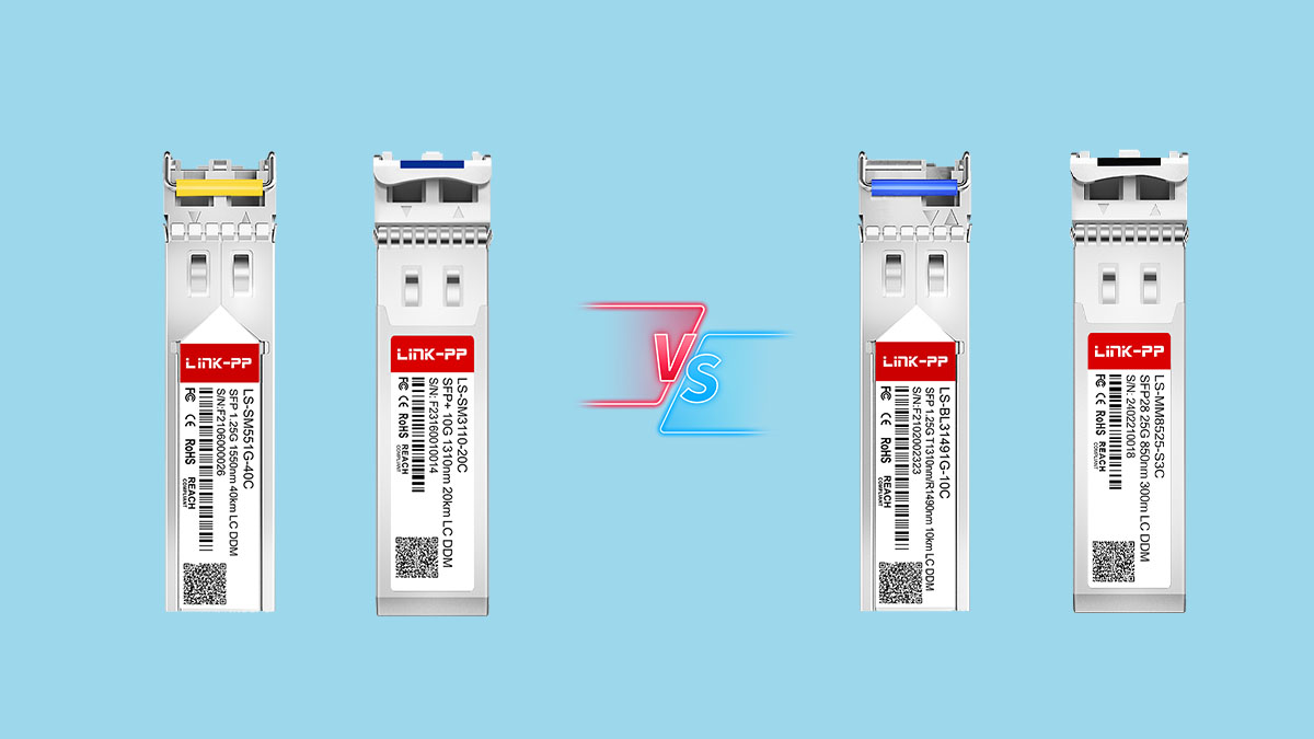
SFP Single Mode vs Multi Mode
SFP optical modules are generally divided into single mode and multi mode types, and the difference between them mainly lies in how light travels through the fiber and how far signals can be transmitted.
Single mode modules use a narrow laser beam that travels through a small core fiber, making them suitable for long-distance communication. Multi mode modules use a wider light path through a larger core fiber, which is typically used for shorter distances.
The table below summarizes the key differences:
| Feature | Single Mode SFP | Multi Mode SFP |
|---|---|---|
| Fiber Type | Small core fiber (OS1/OS2) | Larger core fiber (OM2/OM3/OM4) |
| Transmission Distance | Long-distance (10km–80km+) | Short-distance (up to a few hundred meters) |
| Light Source | Laser-based transmission | LED or VCSEL laser |
| Typical Use Case | Campus, metro, telecom networks | Data center short links |
Single mode SFP LC modules are preferred when transmission distance exceeds typical intra-building requirements. Multi mode solutions are more suitable for short-range, high-density connections inside data centers.
Duplex LC vs BiDi Modules
Another important comparison within SFP LC Single Mode optics is between duplex LC modules and BiDi (bidirectional) modules. Both are designed for single mode fiber, but they use different fiber utilization methods.
Duplex LC modules use two fiber strands—one for transmitting and one for receiving—while BiDi modules transmit and receive data over a single fiber strand using different wavelengths.
The table below highlights their differences:
| Feature | Duplex LC | BiDi Module |
|---|---|---|
| Fiber Usage | Two fibers | One fiber |
| Connector Type | LC duplex | LC simplex |
| Infrastructure Requirement | Higher fiber demand | Lower fiber demand |
| Deployment Flexibility | Standard deployments | Fiber-constrained environments |
Duplex LC modules are widely used in standard enterprise and telecom networks due to their simplicity and stability. BiDi modules are often chosen when fiber resources are limited or when reducing cabling complexity is a priority.
SFP vs SFP+ vs SFP28
SFP LC Single Mode modules also differ based on form factor evolution and supported data rates. The progression from SFP to SFP+ and SFP28 reflects increasing bandwidth requirements in modern networks.
Each generation maintains a similar physical size but supports higher transmission speeds and improved performance.
The table below summarizes key differences:
| Module Type | Data Rate | Typical Use Case | Performance Focus |
|---|---|---|---|
| SFP | 1Gbps | Enterprise access networks | Basic connectivity |
| SFP+ | 10Gbps | Data center and aggregation | High-speed transmission |
| SFP28 | 25Gbps | Cloud and hyperscale networks | High-density bandwidth |
SFP modules are still widely used in access-layer and legacy environments, while SFP+ has become the standard in most modern enterprise and data center deployments. SFP28 is increasingly adopted in cloud and AI-driven infrastructures where bandwidth demand continues to grow rapidly.
✳️ Deployment Best Practices for Stable Fiber Connectivity
Stable fiber connectivity depends heavily on correct deployment practices, not just on selecting the right SFP LC Single Mode module. Even when optics are fully compatible and correctly specified, improper fiber handling, incorrect installation, or lack of maintenance can still lead to unstable links, higher error rates, or unexpected downtime.
Proper Fiber Handling
Proper fiber handling is one of the most important factors in maintaining stable SFP LC Single Mode performance. Fiber cables and LC connectors are highly sensitive to contamination, bending stress, and physical damage, all of which can degrade optical signal quality.
Good handling practices help maintain low insertion loss and consistent link performance over time.
Cleaning LC connectors
LC connector cleanliness directly impacts optical performance, especially in single mode long-distance transmission where signal margins are tighter.
Key practices include:
- Cleaning connectors before every installation
- Using approved fiber cleaning tools or wipes
- Inspecting ferrules before mating connectors
- Avoiding direct contact with fiber end faces
Proper cleaning reduces signal attenuation and prevents avoidable link instability caused by microscopic dust or oil contamination.
Avoiding bend radius violations
Single mode fiber is highly sensitive to bending, and excessive curvature can introduce signal loss or long-term damage.
To maintain stable performance:
- Follow manufacturer-defined minimum bend radius
- Avoid sharp turns behind patch panels or inside racks
- Prevent cable compression in dense routing areas
- Use guided cable pathways instead of free-hanging loops
Maintaining correct bend radius ensures consistent optical propagation and reduces long-term degradation risks.
Cable management recommendations
Proper cable management improves airflow, reduces mechanical stress, and simplifies maintenance operations in fiber deployments.
Recommended practices include:
- Using labeled patch panels for structured organization
- Separating fiber from high-power electrical cables
- Securing cables with appropriate ties without over-tightening
- Maintaining clear routing paths for future expansion
Well-managed cabling infrastructure significantly reduces troubleshooting time and minimizes accidental damage during maintenance.
Installation and Configuration Recommendations
Correct installation and configuration ensure that SFP LC Single Mode modules operate reliably from the moment they are deployed. Even minor misalignment between hardware and configuration can lead to recognition failures or unstable links.
Safe hot-swapping procedures
Most SFP modules support hot-swapping, but improper handling during insertion or removal can still affect system stability.
Best practices include:
- Performing installation during low-traffic periods when possible
- Ensuring the system is stable before inserting modules
- Avoiding repeated rapid insertion and removal cycles
- Confirming module seating is fully secure in the SFP slot
Following controlled hot-swapping procedures helps prevent transient link disruptions and system errors.
Verifying port configuration
Switch or router port settings must match the optical module’s operational parameters to ensure proper link establishment.
Important checks include:
- Matching port speed with module specification (1G, 10G, 25G)
- Ensuring auto-negotiation settings are correctly configured
- Confirming fiber mode compatibility (single mode settings where required)
- Verifying that the port is enabled and administratively up
Incorrect configuration is one of the most common causes of link failure even when hardware is fully compatible.
Monitoring link performance
Monitoring link performance after installation helps ensure that the optical connection remains stable under real traffic conditions.
Key indicators to observe include:
- Optical signal strength (Tx/Rx power levels)
- Link status stability over time
- Error rates such as CRC or frame errors
- Temperature and voltage readings from DDM data
Continuous monitoring helps detect early signs of degradation before they impact network availability.
Preventive Maintenance Strategies
Preventive maintenance is essential for sustaining long-term fiber stability in SFP LC Single Mode deployments. Over time, environmental factors, dust accumulation, and hardware aging can gradually impact optical performance.
Optical signal monitoring
Regular monitoring of optical parameters provides early visibility into potential degradation trends.
Important metrics include:
- Transmit optical power levels
- Receive optical signal strength
- Bit error rate trends
- Temperature and voltage stability
Tracking these values over time allows early detection of weakening optical links before failure occurs.
Periodic inspection
Scheduled physical inspection of fiber infrastructure helps maintain long-term reliability and prevents hidden issues from escalating.
Inspection practices include:
- Checking LC connectors for dust or damage
- Verifying secure fiber connections in patch panels
- Inspecting cable routing for physical stress
- Ensuring proper labeling and documentation accuracy
Regular inspection reduces the risk of undetected physical degradation in fiber systems.
Replacing aging fiber components
Fiber components and optical modules degrade over time due to environmental exposure and continuous operation.
Replacement strategies should consider:
- Aging or frequently unstable transceivers
- Degraded patch cables with increased loss
- Damaged or repeatedly cleaned connectors
- Modules showing inconsistent DDM readings
Timely replacement of aging components helps maintain consistent network performance and avoids sudden failures in critical environments.
✳️ Common Mistakes to Avoid When Selecting SFP LC Single Mode Modules
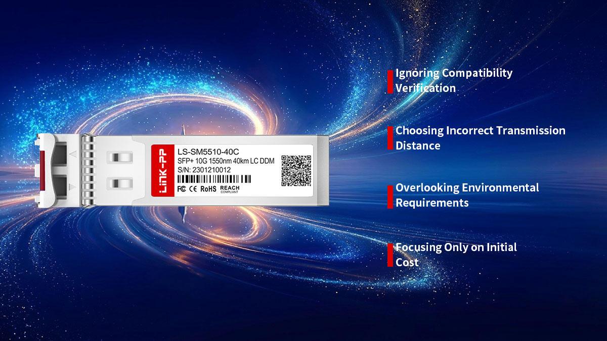
Selecting an SFP LC Single Mode module may look straightforward because key parameters such as speed, wavelength, and connector type are clearly defined. However, in real-world deployments, many network issues originate not from incorrect hardware specifications, but from overlooked selection mistakes.
Ignoring Compatibility Verification
One of the most common mistakes is assuming that any SFP LC Single Mode module with matching specifications will automatically work across all devices. In reality, compatibility depends heavily on firmware validation, vendor coding, and platform-level restrictions.
Failing to verify compatibility in advance can lead to unexpected deployment issues.
Typical consequences include:
- Module not being recognized by the switch or router
- Unsupported transceiver warnings during initialization
- Disabled or limited monitoring functions
- Intermittent link instability under load
Proper verification should always include platform compatibility checks, firmware version confirmation, and validation of module coding requirements before deployment.
Ignoring this step often results in avoidable troubleshooting and potential service interruptions in production environments.
Choosing Incorrect Transmission Distance
Another frequent mistake is selecting a module based on theoretical distance rather than actual deployment requirements. While SFP LC Single Mode modules are available in various reach categories, using an inappropriate distance rating can negatively impact optical performance.
Mismatch in transmission distance may cause either underutilization or signal instability.
Common issues include:
- Using short-reach modules for long fiber links
- Over-specifying long-range optics for short connections
- Incorrect optical budget assumptions
- Increased signal attenuation or power imbalance
Accurate distance planning should consider real fiber path length, connector losses, splice points, and safety margins. Overlooking these factors can lead to unstable or inefficient optical performance.
Overlooking Environmental Requirements
Environmental conditions play a significant role in the long-term reliability of SFP LC Single Mode modules. Selecting a module without considering its operating environment can lead to premature failure or degraded performance.
Environmental mismatches are especially critical in industrial or outdoor deployments.
Common problems include:
- Using commercial-grade modules in high-temperature environments
- Exposure to humidity, dust, or vibration beyond design limits
- Inadequate airflow in high-density rack installations
- Thermal stress from poorly ventilated equipment spaces
Industrial-grade modules are typically required in harsh environments, while commercial-grade optics are suitable for controlled data center conditions. Ignoring this distinction can significantly reduce module lifespan and network stability.
Focusing Only on Initial Cost
Focusing solely on upfront cost is another common mistake that can negatively affect long-term network performance and operational efficiency. While lower-cost modules may appear attractive initially, they may introduce hidden risks over time.
Cost-focused selection often leads to trade-offs in quality, compatibility, and reliability.
Potential long-term impacts include:
- Higher failure rates and replacement frequency
- Increased troubleshooting and maintenance costs
- Limited diagnostic or monitoring capabilities
- Reduced stability under high traffic conditions
A more effective approach is to evaluate total cost of ownership, including reliability, compatibility, maintenance effort, and scalability. Prioritizing long-term operational stability often results in lower overall cost and fewer disruptions in production networks.
✳️ Conclusion
Selecting the right SFP LC Single Mode module is not simply a specification-matching exercise, but a comprehensive decision that directly impacts long-distance optical performance, network stability, and long-term scalability. Across different deployment environments, understanding compatibility, transmission distance, fiber type, and environmental conditions is essential to ensure reliable fiber connectivity. At the same time, evaluating interoperability with switches, routers, and firmware systems helps prevent hidden deployment risks that often appear only after installation.
In most real-world scenarios, successful deployment depends on balancing both technical precision and practical network requirements, especially when working with single mode SFP modules in enterprise, telecom, or data center infrastructures.
To summarize the most important points covered in this guide:
- Compatibility verification is essential before deployment to avoid recognition and interoperability issues
- Transmission distance must match real fiber link requirements rather than theoretical specifications
- Fiber type, connector handling, and environmental conditions directly affect long-term stability
- Firmware validation and vendor coding behavior can significantly influence module performance
- Preventive maintenance and proper installation practices improve overall network reliability
These factors together define whether an SFP LC Single Mode deployment will remain stable and scalable over time.
For modern fiber networks that require consistent performance and flexible deployment options, careful module selection and proper compatibility validation are critical steps in building a reliable optical foundation. Prioritizing tested specifications, verified interoperability, and stable long-term performance will help ensure smoother network operations and reduced maintenance overhead.
For organizations seeking reliable optical connectivity solutions and compatible transceiver options, the LINK-PP Official Store provides a wide range of SFP LC Single Mode modules designed to support enterprise, data center, and telecom applications with consistent performance and compatibility assurance.