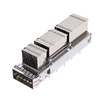
Έχετε δει ποτέ μια ολόκληρη θύρα διακόπτη 800G να κλείνει απροσδόκητα υπό μεγάλη κίνηση δικτύου; Καθώς οι οπτικές μονάδες αυξάνουν την κατανάλωση ενέργειας πέρα από τα 15 έως 20W ανά θύρα, τα τυπικά σχέδια περιβλημάτων δυσκολεύονται να ανταποκριθούν. Όταν η έντονη θερμότητα ενεργοποιεί το θερμικό όριο "βέτο" του συστήματος, μόνο ένας προηγμένος κλωβός QSFP που έχει σχεδιαστεί για μέγιστη απαγωγή θερμότητας μπορεί να διατηρήσει ενεργούς τους κρίσιμους συνδέσμους σας.
Γιατί οι διασυνδέσεις υψηλής ταχύτητας συνεχίζουν να παρουσιάζουν βλάβη ακόμη και όταν οι ανεμιστήρες ψύξης του πλαισίου λειτουργούν σε πλήρη ταχύτητα; Η πραγματική πρόκληση έγκειται στη στενή διεπαφή μεταξύ της θερμικής αγωγιμότητας και της συγκράτησης ηλεκτρομαγνητικών παρεμβολών (EMI). Χωρίς έναν ειδικά σχεδιασμένο σχεδιασμό που ψύχει τα οπτικά στοιχεία ενώ παράλληλα σφραγίζει τις διαρροές ακτινοβολίας υψηλής συχνότητας, το σύγχρονο υλικό κέντρων δεδομένων απλά δεν μπορεί να διατηρήσει πλήρη απόδοση 800G.
↘️ Ποια είναι η απειλή θερμικού βέτο 800G στις σύγχρονες ρυθμίσεις κλουβιών QSFP;
Αυτή η ξαφνική διακοπή λειτουργίας δεν είναι ένα απροσδόκητο ελάττωμα υλικού, αλλά μια ενσωματωμένη διακοπή ασφαλείας γνωστή σε δίκτυα υπερκλίμακας ως θερμικό veto. Όταν οι θερμοκρασίες των μονάδων ξεπεράσουν τα κρίσιμα όρια λειτουργίας, το υλικολογισμικό του διακόπτη ενεργοποιεί αυτόματα μια επείγουσα διακοπή λειτουργίας της θύρας για την προστασία των ευαίσθητων ηλεκτροοπτικών εξαρτημάτων από μόνιμη καύση. Χωρίς ένα κλωβό QSFP υψηλής απόδοσης ικανό να εξάγει θερμότητα συνεχώς, ολόκληρες βαθμίδες spine-leaf μπορούν να βυθιστούν σε απότομες καταστάσεις failover.
Αυξανόμενη θερμότητα σε οπτικούς πομποδέκτες υψηλής ισχύος 800G
Η μετάβαση από 400G σε 800G διπλασιάζει την απόδοση δεδομένων, αλλά αυξάνει επίσης δραματικά την πυκνότητα ισχύος μέσα σε κάθε αποσπώμενο περίβλημα. Οι πομποδέκτες 800G επόμενης γενιάς ενσωματώνουν DSP υψηλής ταχύτητας μαζί με οδηγούς λέιζερ πολλαπλών καναλιών, καταναλώνοντας συχνά 15 έως 20W σε ένα συμπαγές μέγεθος.
Αυτή η συγκεντρωμένη ενέργεια παράγει τεράστια θερμική ροή μέσα σε έναν κλειστό χώρο μικρότερο από μια σοκολάτα. Η απαγωγή αυτού του επιπέδου θερμότητας απαιτεί μια προηγμένη διεπαφή κλωβού QSFP που μπορεί να μεταφέρει θερμικά φορτία μακριά πριν παραβιαστούν τα εσωτερικά όρια σύνδεσης.
Πώς το System Thermal Veto απενεργοποιεί τις υπερθερμαινόμενες θύρες
Τα σύγχρονα λειτουργικά συστήματα μεταγωγέων παρακολουθούν συνεχώς την εσωτερική τηλεμετρία της μονάδας μέσω ενσωματωμένων αισθητήρων Ψηφιακής Οπτικής Παρακολούθησης (DOM). Όταν οι θερμοκρασίες περιβάλλοντος στο πλαίσιο αυξάνονται και οι εσωτερικές θερμοκρασίες του πομποδέκτη υπερβαίνουν τα τυπικά όρια περίπου 70°C ή 85°C, το λειτουργικό σύστημα δικτύου εκδίδει μια ειδοποίηση.
Εάν οι μηχανισμοί ψύξης δεν μπορούν να αντιστρέψουν αυτήν την απότομη αύξηση της θερμοκρασίας μέσα σε δευτερόλεπτα, το σύστημα εκτελεί ένα αυτοματοποιημένο θερμικό βέτο περιορίζοντας την ισχύ του λέιζερ ή απενεργοποιώντας εντελώς τη θύρα. Ενώ αυτή η προστασία αποτρέπει την καταστροφή υλικού, η απροσδόκητη διακοπή λειτουργίας θυρών προκαλεί πτερύγια δρομολόγησης, απώλειες πακέτων και ανασταλτική αναδρομολόγηση κυκλοφορίας σε κρίσιμα για την αποστολή clusters.
Γιατί τα παλαιότερα κλουβιά υποφέρουν από θερμική ολίσθηση και βλάβη γείωσης
Τα τυπικά παλαιού τύπου περιβλήματα έχουν σχεδιαστεί για πομποδέκτες κάτω των 12W και βασίζονται σε παθητικά διάκενα που παγιδεύουν τη στάσιμη θερμότητα. Υπό συνεχή θερμικό κορεσμό 800G, η συνεχής λειτουργία της θερμότητας ενεργοποιεί την ερπυσμό θερμικής διαστολής στις συνδέσεις συγκόλλησης του κλωβού και στις ακίδες γείωσης της πλακέτας τυπωμένου κυκλώματος.
Καθώς η μηχανική ολίσθηση υποβαθμίζει τη συνέχεια της γείωσης, η σύνθετη αντίσταση της διαδρομής επιστροφής αυξάνεται δραματικά κατά μήκος της διεπαφής. Αυτό μετατρέπει το παλαιό περίβλημα σε ένα ενεργό ακτινοβολητή EMI, καταστρέφοντας τον κλωβό Faraday και εκθέτοντας τις γειτονικές λωρίδες 112G PAM4 σε σοβαρό θόρυβο υψηλής συχνότητας.
Πώς η θερμική ολίσθηση και η ηλεκτρομαγνητική παρέκκλιση οδηγούν τον βρόχο ανάδρασης μοιραίου σήματος
Αυτή η βλάβη επηρεάζει την ακεραιότητα του σήματος του φυσικού επιπέδου από δύο μέτωπα ταυτόχρονα. Οι αυξημένες θερμοκρασίες προκαλούν μετατόπιση της διόδου λέιζερ και αυξάνουν τον θερμικό θόρυβο, ενώ η διαφυγή ηλεκτρομαγνητικών παρεμβολών (EMI) καταστρέφει άμεσα τα ακατέργαστα δεδομένα στα κανάλια SerDes υψηλής ταχύτητας.
Καθώς τα ακατέργαστα ποσοστά σφάλματος bit (BER) αυξάνονται, οι μηχανές DSP και Forward Error Correction (FEC) της μονάδας πρέπει να λειτουργούν με το μέγιστο περιθώριο επεξεργασίας για την ανάκτηση κατεστραμμένων καρέ. Αυτή η επιπλέον ψηφιακή επεξεργασία παράγει ακόμη περισσότερη τοπική θερμότητα, επιταχύνοντας την κόπωση της συγκόλλησης και τη θερμική διαφυγή μέχρι ο διακόπτης κεντρικού υπολογιστή να εκτελέσει ένα τελικό θερμικό veto για να αποτρέψει την καταστροφική καύση.
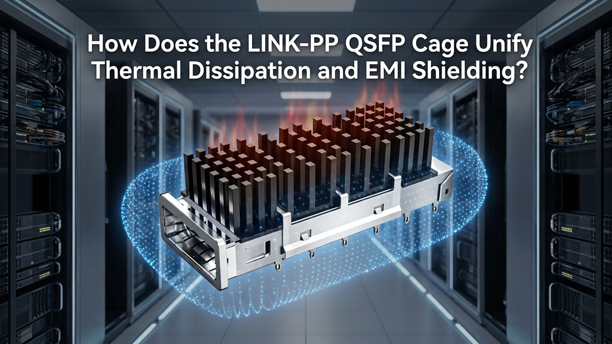
↘️ Πώς λειτουργεί το LINK-PP Το κλουβί QSFP ενοποιεί τη θερμική απαγωγή και την θωράκιση EMI;
Η διακοπή του καταστροφικού κύκλου της θερμικής διαφυγής και της φθοράς της γείωσης απαιτεί την υπέρβαση των ξεχωριστών πρόσθετων ψύξης. Αντιμετωπίζοντας την εξαγωγή θερμότητας και την ηλεκτρομαγνητική θωράκιση ως ένα ενιαίο μηχανικό σύστημα, ένας ολοκληρωμένος σχεδιασμός ψύχει οπτικά υψηλής ισχύος χωρίς να ανοίγει διαδρομές διαρροής ραδιοσυχνοτήτων. Η προηγμένη αρχιτεκτονική κλωβού QSFP από LINK-PP Παρέχει άμεση αγώγιμη ψύξη διατηρώντας παράλληλα συνεχή ηλεκτρική συγκράτηση σε όλο το μπροστινό πλαίσιο.
Άμεση αγωγιμότητα από μονάδα σε πτερύγιο μέσω ενσωματωμένων ψυκτρών
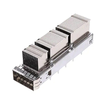
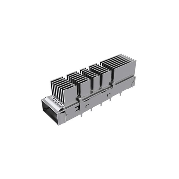
Οι σύγχρονοι οπτικοί πομποδέκτες 800G καταναλώνουν συνήθως 15W έως 20W ισχύος, δημιουργώντας έντονη τοπική θερμότητα μέσα σε συμπαγή περιβλήματα διακοπτών. Για να αποτραπεί η επίτευξη των ορίων θερμικής στραγγαλισμού αυτών των οπτικών, το LINK-PP Το κλουβί LP11GC01070 QSFP-DD με ψύκτρα ενσωματώνει μια ειδική ψύκτρα φερμουάρ 13.5 mm σε στυλ δικτύωσης που ακουμπά απευθείας στο πάνω περίβλημα του πομποδέκτη:
- Πτερύγια υψηλής πυκνότητας με φερμουάρ: Τα αλληλοσυνδεόμενα προφίλ λεπτών πτερυγίων πολλαπλασιάζουν την αποτελεσματική επιφάνεια ψύξης σε σχέση με τα συμβατικά εξωθημένα μπλοκ.
- Αμφίδρομες διαδρομές ροής αέρα: Σχεδιασμένες για να διοχετεύουν τη ροή αέρα τόσο από εμπρός προς τα πίσω όσο και από πλευρά σε πλευρά μέσα σε πυκνό πλαίσιο διακομιστή 1RU και 2RU.
- Άμεση επαφή με την επιφάνεια: Αφαιρεί τις παγιδευμένες τσέπες αέρα μεταξύ του κελύφους της μονάδας και της βάσης της ψύκτρας για άμεση εξαγωγή θερμότητας.
Αυτή η συνεχής θερμική γέφυρα μεταφέρει ενέργεια μακριά από την οπτική μηχανή μέσα σε χιλιοστά του δευτερολέπτου από εκρήξεις έντονης κυκλοφορίας. Η ενσωμάτωση της ψύκτρας απευθείας στο πλαίσιο του κλωβού QSFP διατηρεί τις θερμοκρασίες της μονάδας σταθερές και μακριά από τα όρια τερματισμού λειτουργίας του συστήματος.
Ελαχιστοποίηση της θερμικής αντίστασης της διεπαφής χωρίς διακοπή της γείωσης EMI
Το πάτημα μιας εξωτερικής ψύκτρας σε έναν πομποδέκτη μπορεί εύκολα να διαταράξει την περιμετρική επαφή που απαιτείται για τον αποκλεισμό θορύβου υψηλής συχνότητας. LINK-PP λύνει αυτό το πρόβλημα διαχωρίζοντας μηχανικά τον μηχανισμό θερμικού ελατηρίου από την εξωτερική περίμετρο γείωσης:
- Ισορροπημένα κλιπ ελατηρίων: Εφαρμόστε σταθερή πίεση σύσφιξης προς τα κάτω για να ισιώσετε τα μικροκενά της διεπαφής χωρίς να συνθλίψετε τα εσωτερικά εξαρτήματα.
- Συνεχείς φλάντζες στεφάνης: Ελατηριωτές δακτύλιοι πολλαπλών σημείων περιβάλλουν το μπροστινό άνοιγμα για να διατηρούν ελάχιστη την αντίσταση γείωσης του πλαισίου.
- Ανεξάρτητες Ζώνες Επαφής: Εξασφαλίστε πλήρη θερμική σύζευξη της επιφάνειας χωρίς να διαταράξετε την ηλεκτρική επαφή κατά μήκος του εξωτερικού πλαισίου.
Διατηρώντας τη συνεχή σύνδεση μετάλλου με μέταλλο στην πρόσοψη, το συγκρότημα σταματά τόσο τη συσσώρευση θερμότητας όσο και τη διαρροή ραδιοκυμάτων. Ο πομποδέκτης παραμένει στενά συνδεδεμένος με το πτερύγιο ψύξης, ενώ παραμένει ηλεκτρικά κλειδωμένος μέσα στο κλουβί QSFP.
Βελτιστοποίηση της δυναμικής ροής αέρα του πλαισίου μέσω εξαερισμού με στεγανοποίηση EMI
Η ψύξη πυκνών διακοπτών απαιτεί μεγάλο όγκο αέρα, αλλά οι υπερμεγέθεις οπές εξαερισμού επιτρέπουν στην ενέργεια SerDes υψηλής ταχύτητας να ακτινοβολεί έξω από το πλαίσιο. LINK-PP επιλύει αυτή τη σύγκρουση κατασκευάζοντας μοτίβα εξαερισμού μικροανοιγμάτων κατά μήκος των τοιχωμάτων του κλωβού:
- Διατρήσεις υπομήκους κύματος: Οι διάμετροι των οπών εξαερισμού έχουν μέγεθος αυστηρά κάτω από τα μήκη κύματος αρμονικής ακτινοβολίας 112G PAM4.
- Χαμηλή αεροδυναμική αντίσταση: Η απόσταση μεταξύ των εσωτερικών θαλάμων ελαχιστοποιεί την πτώση στατικής πίεσης, έτσι ώστε οι ανεμιστήρες του πλαισίου να λειτουργούν αποτελεσματικά.
- Ομαλές οδοί ροής αέρα: Ο αέρας κινείται γρήγορα πάνω από τις θερμές επιφάνειες των πτερυγίων χωρίς να δημιουργεί νεκρές ζώνες ή αναταράξεις.
Αυτός ο βαθμονομημένος σχεδιασμός διάτρησης επιτρέπει στους ανεμιστήρες ψύξης να τραβούν τον μέγιστο όγκο αέρα μέσω κάθε οπτικής θύρας. Η ροή αέρα υψηλής ταχύτητας απομακρύνει τη θερμότητα από τις συστοιχίες πτερυγίων, ενώ το περίβλημα QSFP μπλοκάρει αξιόπιστα την ακτινοβολία υψηλής συχνότητας.
Σταθεροποίηση θερμοκρασιών λειτουργίας 800G για την πρόληψη της ερπυσμού εδάφους
Η διατήρηση των θερμοκρασιών λειτουργίας με ασφάλεια κάτω από τους 70°C προστατεύει την υποκείμενη μηχανική δομή της πλακέτας δικτύου. Η χαμηλότερη θερμότητα σταθερής κατάστασης εξαλείφει την τάση διαστολής και συστολής που υποβαθμίζει αργά τις ακίδες πρεσσαρίσματος της πλακέτας τυπωμένου κυκλώματος (PCB) με την πάροδο του χρόνου:
- Οροφές λειτουργίας κάτω των 70°C: Οι χαμηλές θερμοκρασίες σταθερής κατάστασης διατηρούν τα οπτικά συστήματα σε λειτουργία κάτω από τα όρια συναγερμού του εργοστασίου.
- Μηδενική διαστολή ερπυσμού: Οι σταθερές συνθήκες λειτουργίας προστατεύουν τις ασυγκολλήτες καρφίτσες με πίεση από την κυκλική θερμική κόπωση.
- Σταθερές Διαδρομές Επιστροφής: Οι διαδρομές γείωσης χαμηλής σύνθετης αντίστασης παραμένουν άθικτες για δεκάδες χιλιάδες ώρες λειτουργίας.
Η διακοπή της θερμικής ολίσθησης στη διεπαφή της πλακέτας τυπωμένου κυκλώματος (PCB) διακόπτει τον καταστροφικό κύκλο της αυξανόμενης σύνθετης αντίστασης και του διαφυγόντος θορύβου. Τα σύγχρονα οπτικά 800G λειτουργούν ψυχρά, παραμένουν αθόρυβα και παραμένουν μόνιμα προστατευμένα μέσα στο κλουβί QSFP από ξαφνικές θερμικές διαταραχές.
↘️ Αρχιτεκτονική θωράκισης υψηλής συχνότητας EMI μέσα στο κλουβί QSFP
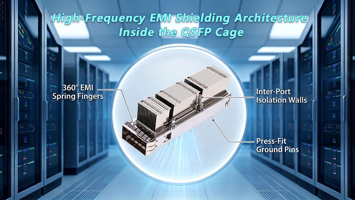
Η ψύξη οπτικών ινών από 15W έως 20W λύνει μόνο το μισό πρόβλημα του φυσικού επιπέδου. Σε ρυθμούς γραμμής 800G, η εξαιρετικά γρήγορη σηματοδότηση 112G PAM4 παράγει σοβαρές αρμονικές υψηλής συχνότητας που μπορούν εύκολα να διαφύγουν μέσω μικροανοιγμάτων στην πρόσοψη του πλαισίου. LINK-PP Ο κλωβός QSFP χρησιμοποιεί μια μηχανικά σχεδιασμένη δομή συγκράτησης κλωβού Faraday που παγιδεύει τον θόρυβο ραδιοσυχνοτήτων μέσα στο περίβλημα διατηρώντας παράλληλα την αδιάλειπτη συνέχεια του εδάφους.
Αποκλεισμός σοβαρής ακτινοβολίας ηλεκτρομαγνητικής ακτινοβολίας υψηλής συχνότητας σε ταχύτητες 800G
Η λειτουργία στα 800G ωθεί τις θεμελιώδεις ηλεκτρικές συχνότητες στο όριο Nyquist των 28 GHz, με τις κρίσιμες αρμονικές να εκτείνονται αρκετά στο φάσμα χιλιοστομετρικών κυμάτων. Σε αυτά τα εξαιρετικά μικρά μήκη κύματος, οι τυπικές μεταλλικές επεξεργασίες και οι συμβατικές μηχανικές αποστάσεις υφίστανται μια αξιοσημείωτη μείωση στην εγγενή αποτελεσματικότητα της θωράκισης — μετατρέποντας ακόμη και μικροσκοπικά ανοίγματα που ήταν ηλεκτρικά αόρατα σε σχέδια 100G σε κεραίες συντονισμού με σχισμές που εκπέμπουν θόρυβο απευθείας σε γειτονικές πλακέτες.
Για την αποφυγή διαρροών υψηλής συχνότητας, ο κλωβός QSFP κατασκευάζεται με τοιχώματα θωράκισης μικροανοίγματος που εξασθενούν τις εκπομπές σήματος σε όλες τις κρίσιμες αρμονικές ζώνες PAM4. Αυτό το πυκνό περίβλημα διατηρεί την ενέργεια ραδιοσυχνοτήτων εντός του κόλπου, προστατεύοντας τα ευαίσθητα ίχνη της μητρικής πλακέτας από την υποβάθμιση του ακτινοβολούμενου θορύβου.
Απρόσκοπτη περιμετρική γείωση για την αποφυγή διαρροής στις υποδοχές
Οι μηχανικές ανοχές μεταξύ της συνδεόμενης οπτικής μονάδας και των εγκοπών της πρόσοψης αναπόφευκτα εισάγουν μικροσκοπικές φυσικές ραφές. LINK-PP Ενσωματώνει ελατηριωτά δάκτυλα πολλαπλών σημείων γύρω από την μπροστινή περίμετρο για να δημιουργεί συνεχή επαφή μεταξύ του περιβλήματος της μονάδας, του πλαισίου του κλωβού και της στεφάνης του πλαισίου.
Αυτή η συνεχής περιμετρική επαφή εξαλείφει τα κενά αέρα και διατηρεί μια διαδρομή εξαιρετικά χαμηλής σύνθετης αντίστασης προς τη γείωση του πλαισίου. Συνδέοντας τη μονάδα στο μεταλλικό πλαίσιο από όλες τις πλευρές, ο κλωβός QSFP σχηματίζει μια ανθεκτική σφράγιση 360 μοιρών που εμποδίζει τις εκπομπές υψηλής συχνότητας να διαφεύγουν γύρω από το πλαίσιο.
Καταστολή ηλεκτρομαγνητικής διαφωνίας μεταξύ θυρών
Στους σύγχρονους διακόπτες 1U 32 ή 64 θυρών, οι θύρες τοποθετούνται σε απόσταση χιλιοστών η μία από την άλλη. Τα αδέσποτα ηλεκτρομαγνητικά πεδία που ακτινοβολούν από έναν μη θωρακισμένο πομποδέκτη μπορούν να συζευχθούν σε γειτονικά κανάλια λήψης, αυξάνοντας τα ποσοστά σφάλματος bit και κατακλύζοντας τα κυκλώματα ισοστάθμισης DSP.
Η αρχιτεκτονική εσωτερικού φραγμού απομονώνει κάθε κόλπο για να διασφαλίσει ότι τα γειτονικά κανάλια δεν παρεμβάλλονται μεταξύ τους. Τα ακόλουθα στοιχεία σχεδιασμού εξηγούν πώς τα χαρακτηριστικά φυσικής θωράκισης μέσα στο κλουβί QSFP εξαλείφουν τις παρεμβολές από θύρα σε θύρα:
| Χαρακτηριστικό θωράκισης | Εφαρμογή Μηχανικής | Άμεσο Λειτουργικό Όφελος |
| Τοίχοι Απομόνωσης μεταξύ Λιμένων | Ενσωματωμένα μεταλλικά φράγματα με βελτιστοποιημένες εγκοπές εξαερισμού μεταξύ των θυρίδων με συρόμενες πόρτες | Καταστέλλει τη σύζευξη κοντινού πεδίου διατηρώντας παράλληλα την ισορροπία της εσωτερικής ροής αέρα |
| Καρφίτσες γείωσης πολλαπλών σημείων | Αποκλειστικές καρφίτσες με πρεσάρισμα που πλαισιώνουν κάθε οπτικό θάλαμο | Παρέχει απομονωμένες, συνεχείς διαδρομές επιστροφής ρεύματος κατευθείαν στη γείωση της πλακέτας τυπωμένου κυκλώματος (PCB) του κεντρικού υπολογιστή |
| Γείωση υποδοχής σε εσοχή | Δευτερεύουσες επαφές γείωσης που βρίσκονται στην εσωτερική άκρη της κάρτας | Διακλαδώνει τον θόρυβο του συνδετήρα πριν συνδεθεί στην κύρια κοιλότητα του πλαισίου |
Συνδυάζοντας φυσικά μεταλλικά φράγματα με απομονωμένες διαδρομές εδάφους, οι πυκνές αναπτύξεις πολλαπλών θυρών λειτουργούν με ρυθμό γραμμής χωρίς υποβάθμιση του θορύβου μεταξύ των καναλιών.
Πληροί αυστηρά πρότυπα ηλεκτρομαγνητικής συμβατότητας (EMC) σε πυκνό πλαίσιο διακόπτη
Τα εταιρικά switches και οι πλατφόρμες top-of-rack πρέπει να υποβάλλονται σε αυστηρές δοκιμές συμμόρφωσης με τους κανονισμούς, συμπεριλαμβανομένων των προτύπων FCC Part 15 Class A και EN 55032. Σε συστήματα υψηλής πυκνότητας 32 ή 64 θυρών, ακόμη και μικρές εκπομπές ραδιοσυχνοτήτων από μεμονωμένες θύρες συσσωρεύονται γρήγορα σε μετρήσιμες αιχμές ακτινοβολίας σε επίπεδο συστήματος.
Η συνεπής σύνδεση μετάλλου με μέταλλο και η γείωση πολλαπλών σημείων διασφαλίζουν ότι οι ακτινοβολούμενες εκπομπές παραμένουν άνετα κάτω από τα κανονιστικά όρια σε όλες τις ζώνες συχνοτήτων PAM4 υψηλής ταχύτητας. Διατηρώντας αξιόπιστα περιθώρια θωράκισης σε κάθε φυσική διεπαφή, αυτός ο σχεδιασμός κλωβού QSFP βοηθά τις ομάδες υλικού να επιτύχουν την τυπική συμμόρφωση με την ηλεκτρομαγνητική συμβατότητα (EMC) χωρίς δαπανηρούς επανασχεδιασμούς πλαισίου ή επιπλέον εσωτερική θωράκιση.
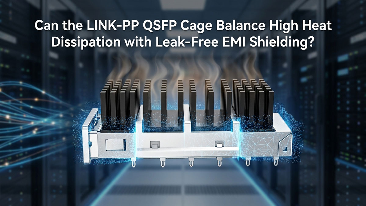
↘️ Μπορεί το LINK-PP Υψηλή απαγωγή θερμότητας ισορροπίας κλωβού QSFP με θωράκιση EMI χωρίς διαρροές;
Ενώ η επιθετική ψύξη και η αυστηρή ηλεκτρομαγνητική συγκράτηση είναι και οι δύο απαραίτητες για τα δίκτυα 800G, οι σχεδιαστές υλικού συχνά τις θεωρούν ως αντίθετες φυσικές δυνάμεις. Η διάνοιξη μεγάλων οπών εξαερισμού για την αποβολή θερμότητας 20W συνήθως καταστρέφει την ασπίδα Faraday, επιτρέποντας τη διαφυγή ακτινοβολίας υψηλής συχνότητας. LINK-PP Το κλουβί QSFP εξαλείφει αυτό το ιστορικό μειονέκτημα συνδυάζοντας την ακριβή διοχέτευση ροής αέρα με απομόνωση ραδιοσυχνοτήτων χωρίς κενά.
Γιατί η προσθήκη ψύκτρων συχνά δημιουργεί διαρροές ηλεκτρομαγνητικής εκκένωσης (EMI)
Η ενσωμάτωση μιας εξωτερικής ψύκτρας σε μια οπτική θύρα συνήθως απαιτεί μεγάλες εγκοπές στο μεταλλικό πλαίσιο, ώστε τα πτερύγια ψύξης να μπορούν να αγγίζουν τον πομποδέκτη. Σε ταχύτητες 800G, αυτά τα ανοίγματα δημιουργούν σοβαρές ηλεκτρικές ευπάθειες:
- Εφέ κεραίας υποδοχής: Οι εγκοπές κατά μήκος του άνω ορίου ευθυγραμμίζονται με τα μήκη κύματος υψηλής συχνότητας, μετατρέποντας τις δομικές ραφές σε κεραίες ακτινοβολούντος διαφράγματος.
- Ασυνεχείς Διαδρομές Επιστροφής: Οι εκτεθειμένες τομές διαταράσσουν τα ρεύματα επιστροφής γείωσης υψηλής συχνότητας κατά μήκος του μεταλλικού περιβλήματος.
- Συντονισμός εσωτερικής κοιλότητας: Η διαφυγούσα ενέργεια PAM4 112G αναπηδά μέσα στο πλαίσιο, αυξάνοντας το επίπεδο θορύβου του συστήματος στις γειτονικές θύρες.
Αυτές οι εγκοπές αφήνουν τα συμβατικά περιβλήματα εκτεθειμένα σε σοβαρές παρεμβολές σήματος. Χωρίς δομική θωράκιση γύρω από τη διεπαφή, οι θερμικές βελτιώσεις υπονομεύουν άμεσα την ακεραιότητα του περιβάλλοντος κλωβού QSFP.
Ενσωματωμένα μηχανικά περιβλήματα που περιέχουν θόρυβο υψηλής συχνότητας
LINK-PP επιλύει αυτή τη σύγκρουση μέσω ενός περιμετρικά θωρακισμένου κολάρου που σφραγίζει το άνοιγμα της ψύκτρας. Αντί να περικλείει τη διάταξη πτερυγίων, αυτό το μεταλλικό πλαίσιο ακριβείας περιβάλλει μόνο τη βάση της ψύκτρας, σφραγίζοντας τη ραφή διεπαφής στην οροφή του κλωβού, αφήνοντας παράλληλα τα άνω πτερύγια πλήρως εκτεθειμένα στις ροές ψύξης του πλαισίου.
Αυτό το περιμετρικό κολάρο λειτουργεί ως αδιάσπαστη επέκταση του κλωβού Faraday κατά μήκος της κινούμενης μηχανικής άρθρωσης. Αναπτύσσοντας συνεχείς φλάντζες ελατηρίου γύρω από τη βάση της ψύκτρας, ο κλωβός QSFP παγιδεύει τις αδέσποτες ηλεκτρομαγνητικές εκπομπές μέσα στην κοιλότητα χωρίς να περιορίζει τη θερμική αγωγιμότητα ή να εμποδίζει τη ροή του αέρα κατά μήκος του άνω συγκροτήματος πτερυγίων.
Διατήρηση της ακεραιότητας της γείωσης χωρίς θυσία των διαδρομών ροής αέρα
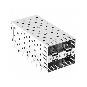
Για τη μεγιστοποίηση της ροής του αέρα χωρίς να ανοίγουν οδοί διαφυγής ραδιοσυχνοτήτων, ο κλωβός διαθέτει μια σειρά από μικροδιατρήσεις σε σχήμα κηρήθρας κατά μήκος των πλευρικών τοιχωμάτων και των πίσω πάνελ. Αυτή η δομική ισορροπία προσφέρει δύο κρίσιμες λειτουργικές λειτουργίες:
- Υψηλής Απόδοσης Αερισμός: Η υψηλή πυκνότητα ανοιγμάτων διατηρεί χαμηλή πτώση στατικής πίεσης, επιτρέποντας στους ανεμιστήρες του πλαισίου να τραβούν σημαντικό όγκο αέρα μέσω των εσωτερικών ζωνών θερμότητας.
- Εξασθένηση κάτω από την αποκοπή του κυματοδηγού: Οι διαστάσεις των οπών εξαερισμού έχουν σχεδιαστεί αρκετά μικρές ώστε η συχνότητα αποκοπής του κυματοδηγού τους να βρίσκεται πολύ πάνω από τις κρίσιμες αρμονικές συχνότητες των σημάτων 112G PAM4, εξασθενώντας πλήρως τα διαφεύγοντα ηλεκτρομαγνητικά κύματα.
Συνδυάζοντας χαμηλή αντίσταση ροής αέρα με υψηλή εξασθένηση RF, ο κλωβός QSFP διατηρεί σταθερές διαδρομές επιστροφής ρεύματος. Ο σχεδιασμός διατηρεί συνεχή επαφή μετάλλου με μέταλλο με τη γείωση του διακόπτη κεντρικού υπολογιστή, ενώ επιτρέπει την ελεύθερη ροή του εξαναγκασμένου αέρα ψύξης.
Σχεδιασμός διπλής προστασίας για ευαίσθητα κανάλια SerDes υψηλής ταχύτητας
Η απόλυτη αξία αυτής της αρχιτεκτονικής διπλής δράσης έγκειται στην προστασία των λωρίδων 112G PAM4 SerDes που εκτείνονται στον σύνδεσμο φυσικής στρώσης. Σε πλάτη σήματος κάτω των μιλιβολτ, τα ζεύγη διαφορικών υψηλής ταχύτητας είναι ευάλωτα τόσο σε τρέμουλο υψηλής θερμοκρασίας όσο και σε ακτινοβολούμενη διασταύρωση:
- Μείωση θερμικού τρεμοπαίγματος: Η ταχεία εξαγωγή θερμότητας διατηρεί το εσωτερικό πυρίτιο του πομποδέκτη δροσερό, αποτρέποντας τη μετατόπιση φάσης που προκαλείται από τη θερμοκρασία.
- Απομόνωση Εγγύς Πεδίου: Συμπαγή μεταλλικά τοιχώματα εμποδίζουν την αδέσποτη ηλεκτρομαγνητική σύζευξη από παρακείμενες λωρίδες υψηλής ταχύτητας.
- Χαμηλά ποσοστά σφάλματος bit: Η διπλή φυσική προστασία διατηρεί καθαρά περιθώρια διαγράμματος ματιών σε ολόκληρο τον προϋπολογισμό συνδέσμων.
Απομονώνοντας ταυτόχρονα τον ηλεκτρικό θόρυβο και απαλλάσσοντας από την έντονη θερμότητα λειτουργίας, το LINK-PP Το κλουβί QSFP προστατεύει τις κρίσιμες διαδρομές δεδομένων από την υποβάθμιση του φυσικού επιπέδου. Οι πάροχοι δικτύου μπορούν να αναπτύξουν πλήρεις ρυθμούς γραμμής 800G σε clusters υψηλής πυκνότητας χωρίς να διακινδυνεύσουν θερμικές διακοπές ή απώλεια πακέτων.
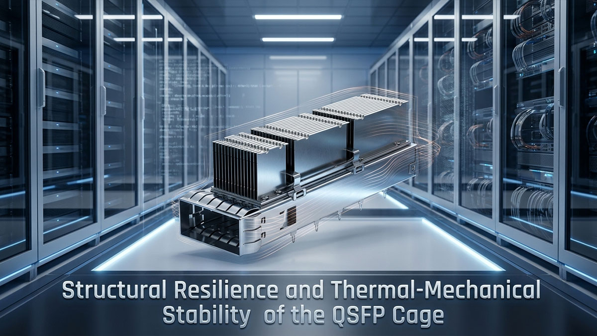
↘️ Δομική Ανθεκτικότητα και Θερμο-Μηχανική Σταθερότητα του Κλωβού QSFP
Ακόμα και οι πιο προηγμένες θερμικές διαδρομές και η θωράκιση Faraday αποτυγχάνουν εάν οι θερμοκρασίες λειτουργίας παραμορφώσουν μηχανικά το συγκρότημα θύρας. Η παρατεταμένη θερμότητα από τα οπτικά 20W προκαλεί σοβαρή φυσική καταπόνηση, με κίνδυνο σχηματισμού κενού, χαλαρών επαφών γείωσης και παραμορφωμένων επιπέδων διεπαφής. LINK-PP Ο κλωβός QSFP βασίζεται σε δομική μηχανική υψηλής εφελκυσμού για να διασφαλίσει ότι η θερμική αγωγιμότητα και η θωράκιση EMI υψηλής συχνότητας παραμένουν σταθερές σε όλη τη διάρκεια των ετών συνεχούς ανάπτυξης.
Άκαμπτο περίβλημα κλουβιού για την αποφυγή θερμικής παραμόρφωσης υπό υψηλή θερμότητα
Η λειτουργία διακοπτών υψηλής πυκνότητας 800G παράγει συνεχή θερμικό κύκλο που μαλακώνει τα τυπικά κράματα χαλκού, οδηγώντας σε δομική χαλάρωση και μικρο-στρέβλωση. Όταν ένα περίβλημα στρεβλώνεται, η επίπεδη βάση της ψύκτρας ανασηκώνεται μακριά από τον οπτικό πομποδέκτη, αυξάνοντας την θερμική αντίσταση και καταστρέφοντας τη θερμική απαγωγή:
- Περίβλημα από ανοξείδωτο χάλυβα υψηλής απόδοσης: Προσφέρει ανώτερη μηχανική ακαμψία για την αντιμετώπιση των τοπικών δυνάμεων θερμικής διαστολής.
- Σταθερή Επιπεδότητα Διεπαφής: Διατηρεί την ομοιόμορφη επαφή της μονάδας με την ψύκτρα για να διατηρεί χαμηλή αγώγιμη θερμική αντίσταση.
- Γεωμετρία χωρίς παραμόρφωση: Αποτρέπει το άνοιγμα του περιμετρικού κενού, εξασφαλίζοντας μηδενική διαρροή ηλεκτρομαγνητικών εκκενώσεων υψηλής συχνότητας κατά τον θερμικό κορεσμό.
Διατηρώντας την ακριβή γεωμετρία του κουτιού του υπό ακραίες θερμοκρασίες λειτουργίας, αυτό το ανθεκτικό κλωβό QSFP αποτρέπει τον θερμικό διαχωρισμό. Η θερμότητα της μονάδας μετακινείται συνεχώς στην ψύκτρα χωρίς κίνδυνο δομικής βλάβης.
Διατήρηση της πίεσης επαφής διεπαφής σε υψηλούς κύκλους εισαγωγής
Οι οπτικοί πομποδέκτες με δυνατότητα σύνδεσης εισάγονται και αντικαθίστανται επανειλημμένα κατά τη διάρκεια ζωής ενός διακόπτη. Εάν τα ελατήρια της ψύκτρας και οι περιμετρικοί δάκτυλοι θωράκισης χάσουν την ελαστική τους μνήμη, η προς τα κάτω θερμική σύσφιξη εξασθενεί και η αντίσταση γείωσης αυξάνεται απότομα:
| Μηχανική Μετρική | Στόχος Μηχανικής | Άμεσος Λειτουργικός Αντίκτυπος |
| Συγκράτηση δύναμης κλιπ ελατηρίου | >95% αρχική δύναμη σύσφιξης μετά από επαναλαμβανόμενους κύκλους | Διατηρεί σταθερή προς τα κάτω πίεση για την εξάλειψη της οριακής θερμικής αντίστασης |
| Ελαστικότητα επαφής | Θερμικά επεξεργασμένα ελατήρια από βηρύλλιο χαλκού | Αποτρέπει τη χαλάρωση της επαφής σε παρατεταμένα θερμικά περιβάλλοντα 70°C+ |
| Συνδεσιμότητα γείωσης | Σταθερή αντίσταση επαφής διεπαφής (<10mΩ ανά δάχτυλο γείωσης) | Σφραγίζει τα περιμετρικά κενά της στεφάνης για μόνιμη καταστολή των αρμονικών εκπομπών 112G PAM4 |
Η σταθερή φυσική πίεση εγγυάται συνεχή συνέχεια μεταξύ μετάλλων στην οπτική διεπαφή. Ο κλωβός QSFP διασφαλίζει ότι η τακτική συντήρηση δεν υποβαθμίζει ποτέ τη θερμική αγωγιμότητα ή την ηλεκτρομαγνητική απομόνωση.
Ασφαλείς μηχανισμοί ασφάλισης κάτω από βαριά φορτία καλωδίων 800G
Τα παχιά καλώδια DAC (Direct Attach Copper) 800G και τα βαριά ενεργά οπτικά συγκροτήματα ασκούν σημαντική ροπή προς τα κάτω στις θύρες του μπροστινού πάνελ. Χωρίς ενισχυμένο μηχανισμό ασφάλισης, αυτή η μηχανική έλξη περιστρέφει τον πομποδέκτη μέσα στην υποδοχή, σπάζοντας τη στεγανοποίηση EMI και τραβώντας το οπτικό κέλυφος μακριά από τον ψύκτη.
Οι ενσωματωμένες ενισχυμένες γλωττίδες ασφάλισης ασφαλίζουν τη μονάδα με ασφάλεια σε πραγματική αξονική ευθυγράμμιση ανεξάρτητα από την εξωτερική τάση του καλωδίου. Αποτρέποντας την κλίση του πομποδέκτη, ο κλωβός QSFP διατηρεί τόσο τη συνεχή θωράκιση περιμέτρου 360 μοιρών όσο και την θερμική επαφή ολόκληρης της επιφάνειας υπό ακραία τάση καλωδίωσης.
Επιλογές επιφανειακής επιμετάλλωσης για βελτιωμένη αντοχή στη διάβρωση και τη θερμότητα
Η μακροχρόνια έκθεση σε υψηλή θερμική ροή επιταχύνει την οξείδωση της επιφάνειας, δημιουργώντας μη αγώγιμες μεμβράνες οξειδίου που θέτουν σε κίνδυνο τις οδούς επιστροφής στο έδαφος χαμηλής σύνθετης αντίστασης. LINK-PP εφαρμόζει εξειδικευμένες επεξεργασίες πολλαπλών στρώσεων επινικελίωσης και κασσιτέρου σε όλες τις δομικές επιφάνειες επαφής:
- Υποπλάκες φραγμού διάχυσης: Αποτρέψτε τη μετανάστευση χαλκού και εξαλείφετε τους κινδύνους γαλβανικής διάβρωσης σε υψηλή θερμοκρασία.
- Φινίρισμα επιφάνειας χαμηλής σύνθετης αντίστασης: Διατηρεί εξαιρετικά χαμηλή ηλεκτρική αντίσταση επαφής σε όλη τη διεπαφή του πλαισίου.
- Προστασία από θερμική οξείδωση: Προστατεύει τις κρίσιμες ζώνες επαφής από την οξείδωση για να διατηρήσει τα αρχικά περιθώρια εξασθένησης των ηλεκτρομαγνητικών εκρήξεων (EMI) με την πάροδο του χρόνου.
Αυτή η ισχυρή χημική προστασία διατηρεί τις ηλεκτρικές και θερμικές διεπαφές άθικτες σε όλη τη διάρκεια δεκαετιών λειτουργίας. Ως αποτέλεσμα, ο κλωβός QSFP προσφέρει ασυμβίβαστη εξαγωγή θερμότητας και θωράκιση χωρίς διαρροές καθ' όλη τη διάρκεια ζωής του υλικού.
↘️ Κρίσιμα πρότυπα επικύρωσης και δοκιμών για κάθε LINK-PP Κλουβί QSFP
Οι θεωρητικές προσομοιώσεις και οι αυστηρές προδιαγραφές υλικών δεν έχουν μεγάλη σημασία χωρίς πρακτική επικύρωση σε εργαστηριακό περιβάλλον υπό πραγματική καταπόνηση στο κέντρο δεδομένων. Για να διασφαλιστεί ότι η δομική ανθεκτικότητα μεταφράζεται σε αξιόπιστη απόδοση πεδίου, LINK-PP δοκιμάζει τα ενσωματωμένα κλουβιά ψύκτρας σε σχέση με πρακτικά θερμικά και ηλεκτρικά κριτήρια αξιολόγησης. Αυτές οι τυποποιημένες διαδικασίες επιβεβαιώνουν ότι κάθε κλουβί QSFP διατηρεί σταθερή θερμική απαγωγή και στεγανή ηλεκτρομαγνητική θωράκιση καθ' όλη τη διάρκεια ζωής του.

Κύκλος λειτουργίας θερμικού θαλάμου υπό μέγιστη ισχύ πομποδέκτη
Τα κλουβιά υποβάλλονται σε κύκλους θερμοκρασίας μέσα σε τυπικούς θαλάμους περιβαλλοντικών δοκιμών για την προσομοίωση συνεχούς λειτουργίας πολλαπλών θυρών. Χρησιμοποιώντας ειδικές μονάδες θερμικών δοκιμών, βαθμονομημένες ώστε να αντιπροσωπεύουν φορτία από 15W έως 20W, οι τεχνικοί παρακολουθούν τις θερμοκρασίες των διεπαφών σε ολόκληρο το εύρος λειτουργίας, ενώ οι δοκιμές θερμικού κύκλου εκτείνονται πέρα από αυτό το εύρος, ώστε να περιλαμβάνουν ακραίες συνθήκες αποθήκευσης και μεταφοράς, διασφαλίζοντας ότι το κλουβί αντέχει τον πλήρη κύκλο ζωής του κέντρου δεδομένων.
Οι βαθμονομημένοι αισθητήρες θερμοστοιχείων που είναι συνδεδεμένοι απευθείας στο περίβλημα της μονάδας και στη βάση της ψύκτρας αυξάνονται υπό ελεγχόμενη ροή αέρα. Επιβεβαιώνοντας ότι οι θερμοκρασίες του περιβλήματος παραμένουν σταθερές και η θερμική αντίσταση δεν αυξάνεται κατά τη διάρκεια παρατεταμένων χρόνων παραμονής, ο κλωβός QSFP επιδεικνύει σαφές θερμικό περιθώριο έναντι των διακοπών θυρών σε επίπεδο συστήματος.
Δοκιμή Ακτινοβολίας EMI Εγγύς Πεδίου και Διαρροής Περιβλήματος
Η ηλεκτρομαγνητική συγκράτηση αξιολογείται σε έναν βαθμονομημένο αναλυτή φάσματος χρησιμοποιώντας φορητούς μαγνητικούς αισθητήρες κοντινού πεδίου (πεδίου-Η) και ηλεκτρικούς αισθητήρες (ηλεκτρονικού πεδίου). Οι τεχνικοί σαρώνουν χειροκίνητα τη στεφάνη της πρόσοψης, τη σύνδεση του κολάρου της ψύκτρας και τις εγκοπές εξαερισμού σε αρμονικές ζώνες υψηλής συχνότητας 112G PAM4.
Αυτή η διαδικασία ανιχνεύει εντοπισμένη διαρροή RF γύρω από μηχανικές ραφές και επαληθεύει ότι οι διατρήσεις αεραγωγών μετριάζουν αποτελεσματικά τον θόρυβο διαφυγής. Η διατήρηση των ακτινοβολούμενων εκπομπών κάτω από τα τυπικά όρια δοκιμών FCC Μέρος 15 και EN 55032 Κλάσης Α διασφαλίζει ότι ο κλωβός QSFP δεν θα παρεμβαίνει στα γειτονικά κανάλια της πλακέτας υποδοχής.
Έλεγχοι αντοχής ελατηρίου επαφής και αντίστασης γείωσης
Η μακροπρόθεσμη συνέχεια της γείωσης επαληθεύεται χρησιμοποιώντας τυπικά μηχανικά εξαρτήματα σύνδεσης. Τα βύσματα δοκιμής οπτικών μονάδων εισάγονται και εξάγονται χειροκίνητα ή πνευματικά για τουλάχιστον 200 κύκλους σύνδεσης για να αξιολογηθεί η διάρκεια ζωής κόπωσης των περιμετρικών δακτύλων και των κλιπ ψύκτρας.
Ένα τετρασύρματο χιλιοστοωμόμετρο μετρά την αντίσταση επαφής χαμηλού επιπέδου κατά μήκος της διεπαφής του πλαισίου του πλαισίου πριν και μετά τον κύκλο λειτουργίας. Διατηρώντας την αντίσταση επαφής κάτω από τα αυστηρά εργοστασιακά όρια και χωρίς να εμφανίζει σπασμένα ελατήρια, ο κλωβός QSFP διασφαλίζει ότι η τακτική συντήρηση των θυρών δεν θα θέσει ποτέ σε κίνδυνο τις διαδρομές γείωσης των ηλεκτρομαγνητικών παρεμβολών ή την θερμική πίεση επαφής.
↘️ Ξεπερνώντας τα θερμικά και ηλεκτρομαγνητικά εμπόδια των 800G με το LINK-PP Κλουβί QSFP

Η ανάπτυξη υποδομής 800G σε κλίμακα απαιτεί την αντιμετώπιση των έντονων θερμικών φορτίων μονάδας 20W και των γρήγορων εκπομπών PAM4 112G ως διασυνδεδεμένης φυσικής πρόκλησης. Τα παραδοσιακά περιβλήματα αποτυγχάνουν όταν η εντοπισμένη θερμότητα προκαλεί θερμική ολίσθηση στις ακίδες γείωσης της πλακέτας τυπωμένου κυκλώματος, διακόπτοντας τη διαδρομή επιστροφής και ενεργοποιώντας έναν καταστροφικό βρόχο ανάδρασης διαρροής EMI, πτώσεων πακέτων και θερμικών βέτο σε επίπεδο διακόπτη. Συνδυάζοντας ψύκτρες με φερμουάρ, εξαερισμό κυματοδηγού υπομήκους κύματος και περίβλημα από ανοξείδωτο χάλυβα υψηλής αντοχής, το... LINK-PP Ο κλωβός LP11GC01070 QSFP-DD σταματά αυτόν τον κύκλο βλάβης στην πηγή — παρέχοντας συνεχή ψύξη και θωράκιση 360 μοιρών χωρίς διαρροές σε όλα τα μπροστινά πάνελ υψηλής πυκνότητας.
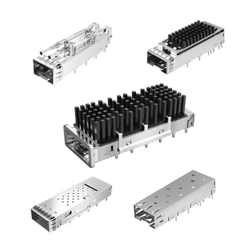
Αυτή η ενοποιημένη προσέγγιση αντιμετωπίζει άμεσα τους δύο πιο κρίσιμους φυσικούς περιορισμούς στον σύγχρονο σχεδιασμό διακοπτών: το θερμικό ύψος και την ηλεκτρομαγνητική συμμόρφωση. Για τους αρχιτέκτονες συστημάτων που σχεδιάζουν clusters τεχνητής νοημοσύνης επόμενης γενιάς και υπερκλιμακωτές δομές spine-leaf, αυτά τα περιθώρια σχεδιασμού υπαγορεύουν τον μακροπρόθεσμο χρόνο λειτουργίας του συστήματος. LINK-PPΗ σειρά προηγμένων λύσεων κλωβού QSFP — όπως φαίνεται από το κλωβό LP11GC01070 1x1 QSFP-DD με ενσωματωμένη ψύκτρα — προσφέρει μηχανική και ηλεκτρική ακεραιότητα αποδεδειγμένη στο πεδίο υπό συνεχή κορεσμό λειτουργίας. Εξερευνήστε δείγματα έτοιμα για παραγωγή, αποκτήστε πρόσβαση σε λεπτομερή μηχανικά σχηματικά και βελτιστοποιήστε τη διάταξη του μπροστινού πίνακα υψηλής ταχύτητας, μεταβαίνοντας στο LINK-PP Επίσημο κατάστημα.