
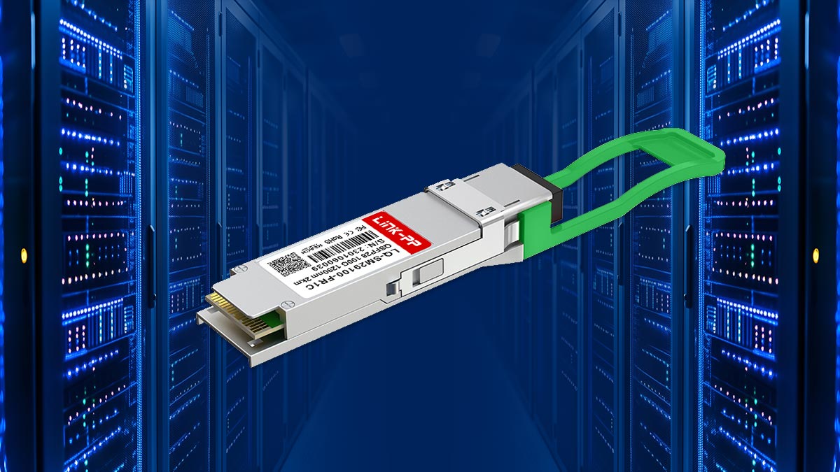
As data center networks continue to scale toward higher bandwidth and lower latency, 100G Ethernet optics have become a critical building block for modern infrastructure. Among the different 100G transceiver options, 100GBASE-FR1 stands out as a key solution designed for single-lambda transmission over single-mode fiber (SMF) using duplex LC connectors.
In simple terms, 100GBASE-FR1 is a 100G optical transceiver standard that transmits data over a single wavelength (single-lambda) instead of multiple wavelengths, enabling simpler optical design while still supporting high-speed performance. It typically operates over 1310 nm wavelength with PAM4 modulation and Forward Error Correction (FEC), delivering reliable transmission over distances of up to around 2 km in data center and campus environments.
Unlike earlier multi-lane solutions such as 100GBASE-LR4, which relies on four separate wavelengths, FR1 simplifies the optical architecture by using a single wavelength while maintaining high data throughput. This makes it especially attractive for high-density data center interconnect (DCI), leaf-spine architectures, and scalable cloud networks, where reducing complexity and increasing port density are key design goals.
Today, network engineers and infrastructure planners often evaluate 100GBASE-FR1 when they need a balance between cost efficiency, reach flexibility, and simplified fiber management—especially when compared with alternatives like DR, LR4, SR4, or SR10 optics.
In this article, we will break down what 100GBASE-FR1 is, how it works, where it is used, and how it compares with other 100G optical standards—helping you choose the right solution for your data center deployment.
🔷 What Is 100GBASE-FR1?
100GBASE-FR1 is a single-lambda 100G Ethernet optical transceiver standard designed for duplex single-mode fiber (SMF) using PAM4 modulation and Forward Error Correction (FEC), typically supporting up to 2 km reach. It is widely used in data center interconnect and high-density switching environments where simplified fiber architecture and efficient bandwidth scaling are required.
In practical terms, 100GBASE-FR1 represents a modern approach to 100G optical transmission by using one optical wavelength (single-lambda) instead of multiple wavelengths. This design significantly reduces optical complexity compared to older multi-lane solutions such as 100GBASE-LR4, which transmits data across four separate wavelengths over single-mode fiber.
Single-Lambda Design (vs. LR4 Multi-Lambda)
The key innovation behind FR1 is its single-lambda architecture. Instead of splitting 100G data into multiple 25G optical lanes across different wavelengths (as in LR4), FR1 transmits the full 100G signal over a single wavelength at 1310 nm using PAM4 modulation.
This approach brings several advantages:
- Simplified optical design (fewer laser sources and optical components)
- Lower power consumption
- Higher port density in modern switches
- Easier scalability for data center networks
By reducing multi-wavelength complexity, FR1 optics are better suited for high-density leaf-spine architectures and cloud-scale deployments.
Duplex LC Interface for SMF Connectivity
100GBASE-FR1 uses a duplex LC connector interface, meaning it transmits and receives data over two strands of single-mode fiber:
- One fiber for transmitting (Tx)
- One fiber for receiving (Rx)
This is a major difference from parallel optics like SR4 or SR10, which rely on MPO/MTP connectors and multiple fiber pairs.
The use of standard duplex LC connectors makes FR1 especially attractive for:
- Existing SMF cabling infrastructure
- Upgrades from 10G/25G duplex fiber systems
- Simplified fiber management in data center racks
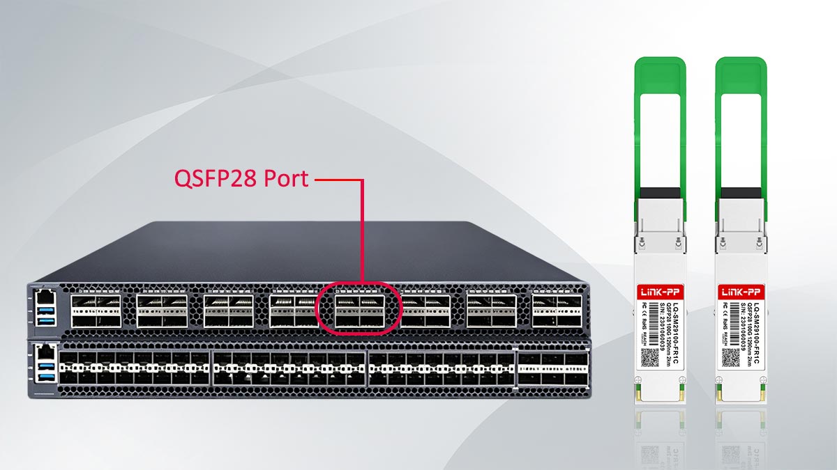
QSFP28 and QSFP-DD Form Factors
100GBASE-FR1 optics are commonly available in industry-standard pluggable form factors, including:
- QSFP28 (Quad Small Form-factor Pluggable 28)
- QSFP-DD (Quad Small Form-factor Pluggable Double Density)
These form factors enable FR1 to integrate seamlessly into modern high-speed switches and routers. QSFP28 is widely used in current 100G deployments, while QSFP-DD supports higher-density platforms and future migration toward 400G systems.
In both cases, FR1 optics are designed to be hot-pluggable, allowing network operators to upgrade or replace modules without shutting down the system.
Overall, 100GBASE-FR1 is best understood as a simplified, high-efficiency 100G optical standard built for modern data centers, combining single-wavelength transmission, duplex LC connectivity, and flexible form factor support to meet growing bandwidth demands.
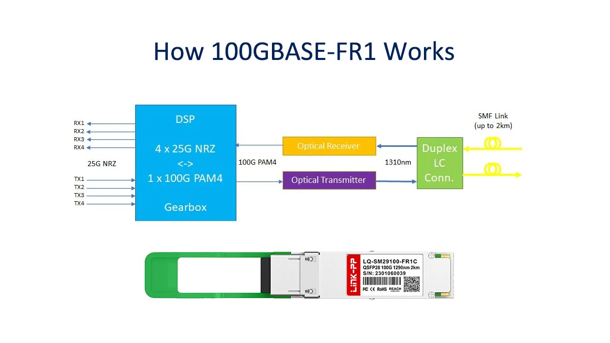
🔷 How 100GBASE-FR1 Works (PAM4 + FEC Explained Simply)
100GBASE-FR1 achieves high-speed 100G transmission by combining PAM4 modulation, Forward Error Correction (FEC), and single-wavelength (single-lambda) optical transmission at 1310 nm over duplex single-mode fiber. This combination allows FR1 to deliver high bandwidth efficiently while maintaining signal integrity over distances typically up to 2 km in data center environments.
PAM4 Modulation Basics
At the core of 100GBASE-FR1 is PAM4 (Pulse Amplitude Modulation with 4 levels). Unlike traditional NRZ signaling, which transmits 1 bit per symbol, PAM4 transmits 2 bits per symbol by using four distinct voltage or optical levels.
This effectively doubles data capacity without increasing the symbol rate, making it possible to achieve 100G speeds within existing optical constraints.
Key benefits of PAM4 in FR1:
- Higher data rate without increasing bandwidth
- Efficient use of optical spectrum
- Enables single-lambda 100G transmission
However, PAM4 is more sensitive to noise and signal distortion, which leads directly to the need for FEC.
Why Forward Error Correction (FEC) Is Required
Because PAM4 uses tighter signal spacing between levels, it is more susceptible to transmission errors compared to NRZ signaling.
To maintain reliability, Forward Error Correction (FEC) is applied:
- Detects and corrects bit errors at the receiver
- Improves overall link performance
- Enables longer reach (up to ~2 km for FR1)
Without FEC, PAM4-based 100G links would suffer from unacceptable error rates in real-world data center environments.
Single-Wavelength Transmission at 1310 nm
Unlike 100GBASE-LR4, which uses four separate wavelengths, FR1 uses a single optical wavelength (1310 nm) to carry the full 100G signal.
This single-lambda design:
- Simplifies optical components (fewer lasers and filters)
- Reduces power consumption
- Improves scalability in dense switching environments
- Minimizes complexity in fiber management
The 1310 nm wavelength is chosen because it offers:
- Low attenuation in single-mode fiber
- Stable performance over short-to-medium data center distances
Why It Enables Higher Density Optics
The combination of PAM4 + single-lambda + duplex LC design allows FR1 to achieve significantly higher port density in modern switches.
Compared to multi-lane optics:
- Fewer optical components per port
- Reduced fiber count (only 2 fibers per link)
- Smaller physical footprint in QSFP28/QSFP-DD cages
- Lower overall power per bit transmitted
This makes FR1 particularly well-suited for leaf-spine architectures and hyperscale data center designs, where rack space and fiber management efficiency are critical.
100GBASE-FR1 uses PAM4 modulation to encode 2 bits per symbol, combined with Forward Error Correction (FEC) to maintain signal integrity over single-mode fiber. It transmits all 100G data over a single 1310 nm wavelength (single-lambda) using duplex LC connectors, enabling simplified fiber design and higher port density in data center networks while supporting reaches of up to approximately 2 km.
🔷 100GBASE-FR1 vs. DR vs. LR4 vs. SR4 (Key Differences)
When selecting a 100G optical transceiver, the most important decision factors are reach distance, fiber type, optical architecture, and connector type. 100GBASE-FR1 is often compared with DR, LR4, and SR4 because they all serve different segments of data center and campus network design.
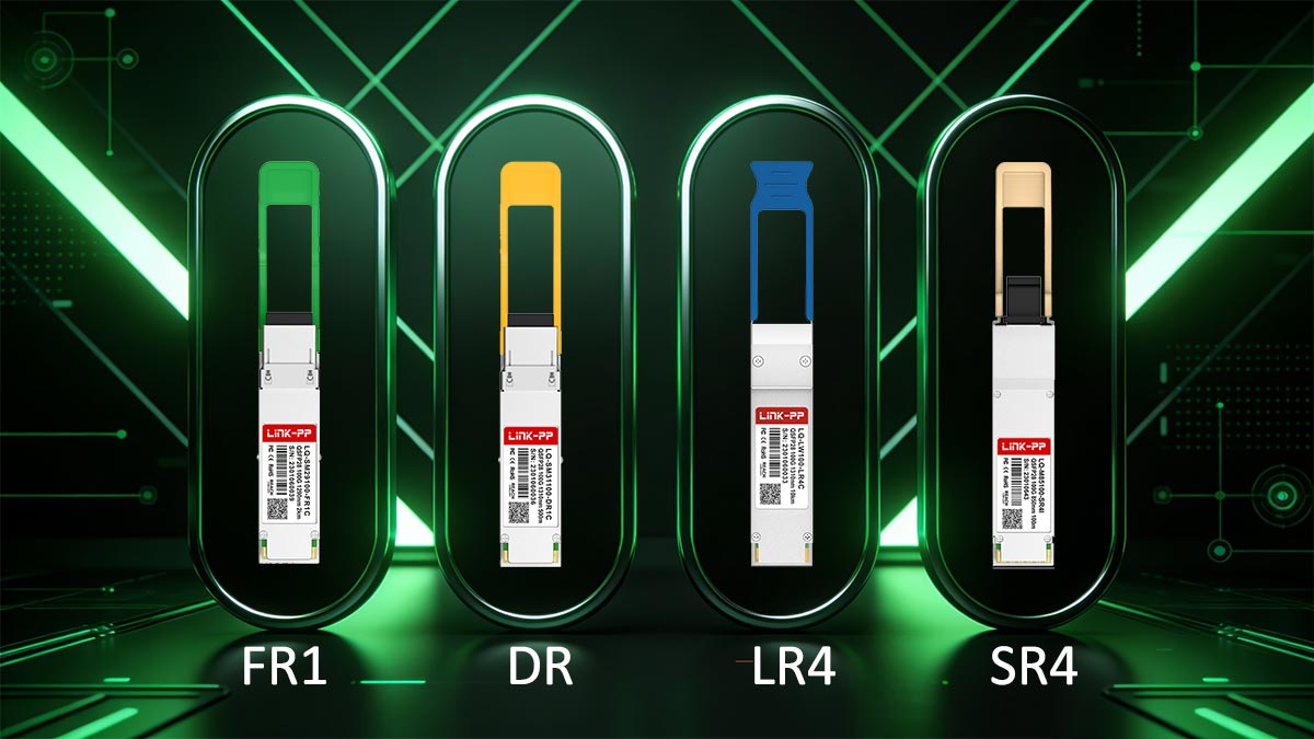
Below is a clear side-by-side comparison to help you quickly identify the right solution.
100G Optics Comparison Table
| Standard |
Reach |
Fiber Type |
Wavelength Design |
Connector Type |
Architecture |
Typical Use Case |
Relative Cost |
| 100GBASE-SR4 |
Up to 100 m (OM4) |
Multimode fiber (MMF) |
Multi-lane (4x25G) |
MPO/MTP |
Parallel optics |
Short-reach inside racks / ToR connections |
Low |
| 100GBASE-DR |
Up to 500 m |
Single-mode fiber (SMF) |
Single-lambda (PAM4) |
Duplex LC |
Single-lane |
Data center leaf-spine short reach |
Medium |
| 100GBASE-FR1 |
Up to 2 km |
Single-mode fiber (SMF) |
Single-lambda (PAM4) |
Duplex LC |
Single-lane |
Data center interconnect / campus links |
Medium |
| 100GBASE-LR4 |
Up to 10 km |
Single-mode fiber (SMF) |
Multi-wavelength (4λ) |
Duplex LC |
WDM (4 lanes) |
Metro / long data center links |
High |
Key Differences Explained
- Reach:
SR4 is designed for very short multimode links, while FR1 extends up to 2 km, and LR4 reaches up to 10 km.
- Fiber Type:
SR4 uses multimode fiber (MMF), while DR, FR1, and LR4 all use single-mode fiber (SMF), which supports longer distances and better scalability.
- Wavelength Design:
- SR4 and LR4 use multi-lane or multi-wavelength designs
- DR and FR1 use single-lambda PAM4 architecture, which simplifies optics and improves density
- Connector Type:
- SR4 uses MPO/MTP connectors (parallel fiber)
- DR, FR1, and LR4 use standard duplex LC connectors, making them easier to deploy in existing fiber plants
- Cost and Deployment Scenarios:
- SR4: lowest cost, short-reach inside racks
- DR: cost-efficient for short SMF leaf-spine
- FR1: balanced option for medium-reach (up to 2 km)
- LR4: higher cost, long-reach metro or campus backbone
Simple Selection Logic (Quick Decision Guide)
- ≤ 100 m, MMF available → SR4
- ≤ 500 m, SMF leaf-spine → DR
- ≤ 2 km, campus or DCI → FR1
- ≤ 10 km, metro backbone → LR4
This comparison shows that 100GBASE-FR1 fills the critical “middle layer” gap between DR and LR4, making it one of the most flexible and widely used 100G single-lambda solutions in modern data centers.
🔷 When Should You Use 100GBASE-FR1?
100GBASE-FR1 is designed for medium-reach, high-density 100G Ethernet deployments, making it especially suitable when you need more distance than DR optics but do not require long-reach LR4 solutions. It fills a key “middle layer” in modern data center optical architectures, typically supporting links up to approximately 2 km over single-mode fiber (SMF).
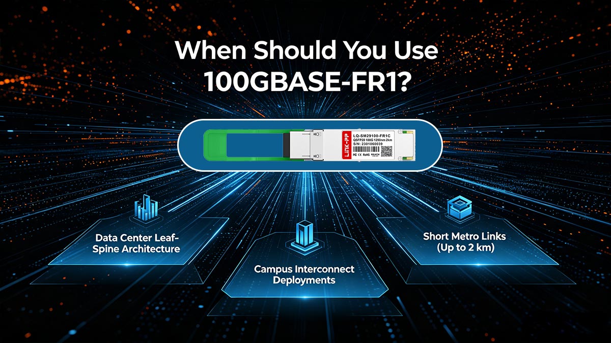
1. Data Center Leaf-Spine Architecture
One of the most common use cases for 100GBASE-FR1 is in leaf-spine data center networks, where switches are interconnected in a non-blocking fabric.
FR1 is used when:
- Leaf switches are located across different rows or pods
- SMF cabling is already deployed
- DR (500 m) is not sufficient for the physical layout
Its single-lambda design helps simplify high-density switch interconnects while maintaining reliable 100G throughput across distributed racks.
2. Campus Interconnect Deployments
FR1 is also widely used in campus network environments, where multiple data center buildings or network halls need to be connected.
Typical FR1 advantages in campus use cases:
- Supports inter-building fiber links
- Works efficiently over existing SMF infrastructure
- Avoids the complexity of multi-lambda LR4 optics for moderate distances
This makes FR1 a cost-effective option for enterprise campus backbone connections.
3. Short Metro Links (Up to 2 km)
Another key deployment scenario is short metro or edge-to-core connectivity, typically within a range of up to 2 km.
FR1 is suitable when:
- The network spans adjacent buildings or nearby facilities
- Latency-sensitive traffic requires direct optical links
- Operators want to avoid higher-cost LR4 or LR1 solutions
Because FR1 uses PAM4 with FEC over a single wavelength, it maintains stable performance while keeping optical design simple.
4. Replacement for 100GBASE-DR When Reach Is Insufficient
Many networks originally designed for 100GBASE-DR (up to 500 m) eventually encounter distance limitations as infrastructure expands.
FR1 becomes the natural upgrade path when:
- Existing DR links exceed 500 m
- Network expansion increases rack-to-rack distance
- A seamless upgrade is needed without changing switch architecture
In these cases, FR1 provides extended reach (up to ~2 km) while maintaining similar duplex LC and single-lambda design principles.
Best Fit Scenarios (Quick Reference)
Use 100GBASE-FR1 when:
- ✔ You are building or scaling a leaf-spine data center network
- ✔ Your SMF links exceed 500 m but stay within ~2 km
- ✔ You need duplex LC-based 100G optics (no MPO required)
- ✔ You are connecting multiple buildings in a campus network
- ✔ You want a simpler alternative to 100GBASE-LR4 multi-lambda optics
- ✔ You are replacing 100GBASE-DR due to reach limitations
- ✔ You require high-density, low-complexity 100G interconnects
100GBASE-FR1 is best positioned as a flexible medium-reach 100G solution, bridging the gap between short-reach DR optics and long-reach LR4/LR1 optics. It is most valuable in environments where fiber distance, scalability, and simplicity must be balanced within modern data center architectures.
🔷 Compatibility Requirements for 100GBASE-FR1
Although 100GBASE-FR1 is designed to simplify 100G optical deployments, compatibility depends on several critical physical and system-level requirements. In real-world deployments, most FR1 issues are not caused by the optic itself, but by mismatches in fiber type, switch support, or vendor-specific coding rules.
Below are the key compatibility factors you must check before deployment.
SMF OS2 Fiber Requirement
100GBASE-FR1 requires single-mode fiber (SMF), specifically OS2-grade fiber, to support its 1310 nm single-lambda transmission over distances up to ~2 km.
Key points:
- Must use OS2 single-mode fiber (not OM3/OM4 multimode)
- Optimized for low attenuation over longer distances
- Supports stable performance for 100G PAM4 signals
Common mistake: attempting to run FR1 over multimode fiber (MMF), which will cause link failure or severe signal degradation.
Duplex LC Connector Requirement
FR1 uses a duplex LC interface, meaning:
- One fiber for transmission (Tx)
- One fiber for reception (Rx)
This is important because:
- It enables reuse of existing duplex SMF infrastructure
- It avoids MPO/MTP complexity used in SR4/SR10
- It simplifies patch panel and rack-level cabling
FR1 is therefore much easier to deploy in environments already using LC-based SMF cabling systems.
Switch Support (QSFP28 / QSFP-DD Ports)
To use 100GBASE-FR1, your network equipment must support compatible 100G pluggable transceiver ports, typically:
- QSFP28 ports (most common in current 100G switches)
- QSFP-DD ports (for higher-density platforms and future scalability)
Important considerations:
- The switch must support 100G PAM4 optics
- Port firmware must recognize FR1 optical profiles
- Some platforms may require software upgrades for compatibility
Without proper port support, the module may not initialize or may run in a degraded state.
Vendor Coding and Compatibility Issues
One of the most practical challenges in real deployments is transceiver vendor coding.
Key points:
- Many switch vendors (Cisco, Arista, Juniper, etc.) enforce optical module validation
- Third-party FR1 modules may require compatibility coding
- Some platforms restrict or warn against non-certified optics
Common issues include:
- “Unsupported transceiver” warnings
- Port disabled or degraded mode
- Link not establishing despite correct physical connection
Best practice: always verify switch compatibility matrix before deployment
FEC (Forward Error Correction) Support Requirements
Because FR1 uses PAM4 modulation, it depends heavily on Forward Error Correction (FEC) to maintain signal integrity.
Compatibility requirements:
- Switch must support RS-FEC or equivalent FEC scheme
- FEC must be enabled on both ends of the link
- Mismatched FEC settings can cause:
- high bit error rates
- unstable links
- intermittent connectivity
FR1 links may still appear “up” without correct FEC, but performance will be unreliable.
Key Takeaway
To ensure successful deployment of 100GBASE-FR1, all four layers must align:
- ✔ OS2 single-mode fiber (SMF)
- ✔ Duplex LC cabling infrastructure
- ✔ Compatible QSFP28/QSFP-DD switch ports
- ✔ Correct vendor coding and software support
- ✔ Enabled FEC on both ends of the link
When these conditions are met, FR1 delivers a highly reliable, scalable, and simplified 100G optical solution for modern data center networks.
🔷 100GBASE-FR1 in 400G Breakout Architectures
As data centers transition from 100G to 400G and beyond, breakout architectures have become a key design strategy for maximizing switch port utilization and reducing upgrade costs. In this context, 100GBASE-FR1 plays an important role as a downstream 100G optics option in 400G-to-100G breakout networks, especially in single-mode fiber (SMF) environments.
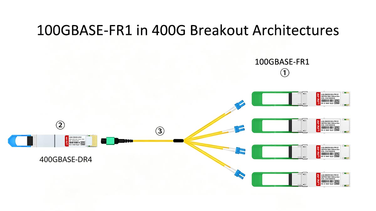
400G → 4×100G Breakout Use Case
One of the most common modern deployments is the 400G QSFP-DD to 4×100G breakout architecture.
In this model:
- A single 400G port is split into four independent 100G links
- Each 100G lane can connect to separate leaf switches, servers, or aggregation nodes
- This significantly improves port efficiency and switch scalability
100GBASE-FR1 is often used on the 100G end of these breakout connections, especially when:
- The target links exceed DR reach (500 m)
- The network requires duplex LC-based SMF infrastructure
- Simpler cabling is preferred over MPO-based SR4 solutions
FR1 vs. LR1 Positioning in Breakout Networks
In breakout architectures, both FR1 and LR1 are commonly evaluated, but they serve different roles:
| Feature |
100GBASE-FR1 |
100GBASE-LR1 |
| Reach |
~2 km |
~10 km |
| Fiber |
SMF (OS2) |
SMF (OS2) |
| Wavelength |
Single-lambda (1310 nm) |
Single-lambda (1310 nm) |
| Use Case |
Data center + campus breakout |
Metro + long-haul breakout |
| Cost |
Lower |
Higher |
Key insight:
- FR1 is optimized for cost-efficient, medium-reach breakout
- LR1 is used when breakout extends into metro-scale or inter-site links
In most hyperscale data centers, FR1 is preferred because it offers a better balance of reach, cost, and port density.
Switch Aggregation Design with FR1
In modern leaf-spine and aggregation layer architectures, FR1 supports efficient scaling by enabling:
- High-density 100G leaf switch connections
- Simplified duplex LC cabling instead of MPO-based trunks
- Flexible inter-rack or inter-row connectivity
- Easier migration from 100G to 400G core layers
A typical design pattern:
- Core layer: 400G switches (QSFP-DD)
- Aggregation layer: 100G FR1 uplinks
- Access layer: 25G/50G server connections
This structure allows operators to scale bandwidth without redesigning the entire fiber plant.
High-Density Data Center Scaling Benefits
100GBASE-FR1 contributes directly to high-density scaling strategies, especially in cloud and hyperscale environments:
- Reduces fiber complexity (duplex LC vs MPO)
- Enables more ports per rack unit (higher port density)
- Supports modular growth in 100G increments
- Simplifies 400G breakout adoption path
- Reduces power per bit compared to multi-lane optics
Because FR1 uses a single-lambda PAM4 architecture, it also aligns well with modern switch ASICs optimized for high-speed serial lanes.
Key Takeaway
In 400G breakout architectures, 100GBASE-FR1 serves as a cost-efficient and scalable 100G endpoint solution, bridging high-speed core networks with flexible 100G aggregation layers. It is especially valuable when designing high-density data centers that prioritize duplex LC simplicity, SMF reach up to 2 km, and smooth migration from 100G to 400G infrastructures.
🔷 Common Problems and Deployment Mistakes
Although 100GBASE-FR1 is designed to simplify 100G deployments, most real-world issues come from misconfiguration, incorrect assumptions, or compatibility oversights rather than the optics themselves. Understanding these common mistakes is essential for ensuring stable, high-performance links in production networks.
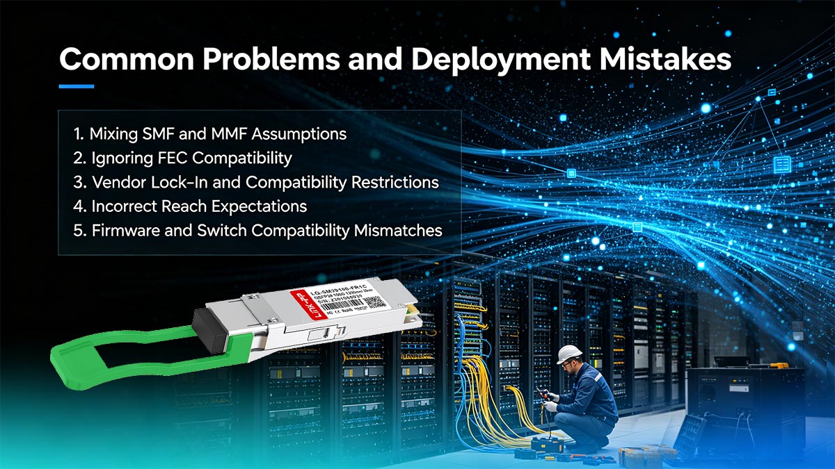
1. Mixing SMF and MMF Assumptions
One of the most frequent deployment errors is assuming fiber compatibility incorrectly.
Key issue:
- FR1 requires single-mode fiber (SMF, OS2)
- Some users mistakenly attempt deployment over multimode fiber (MMF, OM3/OM4)
Why this fails:
- FR1 operates at 1310 nm single-lambda transmission
- MMF is optimized for shorter-wavelength multimode signaling
- Result: severe attenuation, unstable link, or complete failure
Always verify fiber plant type before installation.
2. Ignoring FEC Compatibility
Because FR1 uses PAM4 modulation, it relies heavily on Forward Error Correction (FEC) to maintain signal integrity.
Common mistake:
- One or both switches have FEC disabled or mismatched
Impact:
- High bit error rate (BER)
- Intermittent link flapping
- “Link up but unstable” behavior
Best practice:
- Ensure RS-FEC or equivalent is enabled on both ends
- Confirm identical FEC settings across devices
3. Vendor Lock-In and Compatibility Restrictions
Many enterprise switches enforce strict transceiver validation policies.
Issues include:
- “Unsupported transceiver” warnings
- Ports disabled when non-certified optics are used
- Firmware-based blocking of third-party modules
This is especially common with major vendors such as Cisco, Arista, and Juniper.
Mitigation strategies:
- Use vendor-coded compatible FR1 modules
- Verify switch optics compatibility matrix before deployment
- Ensure firmware allows third-party optics if required
4. Incorrect Reach Expectations
Another common misunderstanding is overestimating FR1’s reach capabilities.
Reality:
- FR1 is designed for up to ~2 km over SMF
- It is not a metro or long-haul solution
Typical mistakes:
- Using FR1 for >2 km campus links
- Assuming it behaves like LR4 (10 km)
- Ignoring fiber loss budgets in real environments
Result:
- Marginal link performance
- Increased error rates
- Unexpected link failures under load
5. Firmware and Switch Compatibility Mismatches
Even when hardware is correct, software compatibility can still cause failures.
Common issues:
- Switch firmware does not recognize FR1 optics
- Outdated transceiver libraries
- Missing support for PAM4-based 100G modules
Symptoms:
- Optic not detected
- Link stays down despite correct cabling
- Reduced operational mode or warning states
Best practice:
- Always update switch firmware before deploying FR1
- Validate optical module support in release notes
- Test in staging environment before production rollout
Key Takeaway
Most 100GBASE-FR1 deployment issues are not hardware failures but planning and compatibility oversights, especially around fiber type, FEC configuration, vendor restrictions, and firmware support.
A successful FR1 deployment requires aligning four critical layers:
- ✔ Correct SMF (OS2) infrastructure
- ✔ Proper FEC configuration on both ends
- ✔ Verified vendor/switch compatibility
- ✔ Accurate reach and design assumptions
When these factors are properly managed, FR1 delivers a stable, scalable, and high-density 100G solution for modern data center networks.
🔷 FAQ About 100GBASE-FR1 Single-Lambda 100G Optics
❓ What is the reach of 100GBASE-FR1?
100GBASE-FR1 typically supports up to 2 km over single-mode fiber (OS2). It is designed for short-to-medium reach applications such as data center interconnect, leaf-spine links, and campus connectivity, where DR optics (500 m) are not sufficient but LR4 (10 km) is excessive.
❓ Is FR1 compatible with DR optics?
No, FR1 and DR are not directly compatible in terms of optical parameters.
- DR: ~500 m reach
- FR1: ~2 km reach
Although both use single-mode fiber and duplex LC connectors, they differ in optical reach budgets and system design assumptions. They can only interoperate if both ends support the same optical standard or through proper conversion/architecture design.
❓ Does FR1 use single-mode fiber?
Yes, 100GBASE-FR1 uses single-mode fiber (SMF), specifically OS2-grade fiber.
It operates at 1310 nm wavelength using single-lambda PAM4 transmission, which is optimized for low-loss, longer-distance optical transmission compared to multimode fiber (MMF).
❓ What is the difference between FR1 and LR4?
The main differences are in wavelength architecture and reach:
- FR1: single-lambda design, up to ~2 km
- LR4: four-wavelength (WDM) design, up to ~10 km
FR1 uses a simpler optical structure with PAM4 and FEC, while LR4 uses four separate optical channels without PAM4, making LR4 suitable for longer metro or backbone links.
❓ Can FR1 be used in 400G breakout?
Yes, 100GBASE-FR1 is commonly used in 400G-to-100G breakout architectures.
In these deployments:
- One 400G port is split into 4×100G links
- FR1 provides a duplex LC-based SMF 100G endpoint
- It is ideal for medium-reach breakout scenarios up to ~2 km
FR1 is often preferred over DR in breakout designs when additional reach or campus connectivity is required.
🔷 How to Choose the Right 100G Data Center Optics
Selecting the right 100G optical transceiver is ultimately a network design decision, not just a product choice. The best option depends on your required reach, fiber infrastructure, switch compatibility, and future scalability plans.
At a high level, 100G optics fall into a simple decision path:
- Short-reach (≤100 m, MMF available) → SR4
- Short SMF (≤500 m) → DR
- Medium SMF (≤2 km) → FR1
- Long-reach (≤10 km) → LR4
Within this framework, 100GBASE-FR1 plays a critical middle role, especially in modern data centers that are expanding across multiple rows, pods, or buildings while still relying on duplex LC single-mode fiber infrastructure.
Practical Selection Guidelines
To choose the right 100G optics, evaluate the following factors:
- Fiber type available: SMF (OS2) vs MMF (OM3/OM4)
- Required reach: intra-rack, intra-building, campus, or metro
- Connector infrastructure: duplex LC vs MPO/MTP
- Switch support: QSFP28 or QSFP-DD compatibility and FEC requirements
- Future scaling needs: especially 400G breakout planning
If your network requires balanced reach, simplified cabling, and high-density deployment, 100GBASE-FR1 is often the most flexible and future-ready option.
Final Recommendation
In modern data center architectures, the key is not just meeting today’s bandwidth demand—but ensuring smooth evolution toward 400G and beyond. That is why many operators adopt FR1 as a strategic mid-range 100G solution, bridging DR and LR4 while supporting scalable leaf-spine and breakout designs.
If you are planning a new deployment or upgrading an existing 100G infrastructure, choosing the right optical module early can significantly reduce long-term complexity and cost.
👉 Explore compatible and high-performance optical transceivers at the LINK-PP Official Store, where you can find reliable 100G solutions designed for data center, enterprise, and telecom applications.


