As data centers scale up to handle massive traffic, network engineers frequently hit a frustrating wall: the 100-meter distance limit of standard short-reach optics over multi-mode fiber. Replacing existing fiber infrastructure with single-mode alternatives is often too expensive, creating a major bottleneck for expanding data center footprints. This is exactly where the QSFP28-ESR4 optical transceiver comes into play, offering a smart fix for extending network reach without a total overhaul.
The core challenge lies in bridging the gap between standard multi-mode limits and cost-effective data transmission. Traditional optics simply lack the optical budget to push high-speed 100G signals across larger data center halls. By upgrading to extended short-reach technology, network operators can seamlessly extend their links up to 300m while fully preserving their current cabling setup.
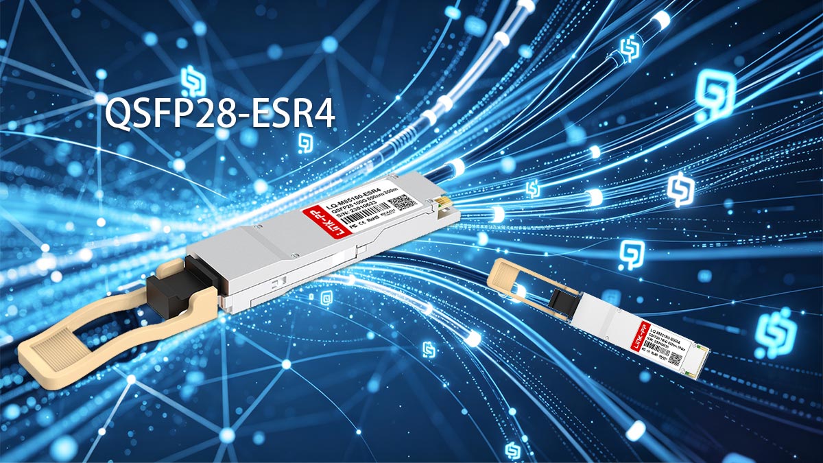
↘️ Introduction to QSFP28-ESR4 Optical Transceiver Technology
Modern high-density data centers require optical solutions that balance high throughput, power efficiency, and extended transmission distances. The emergence of QSFP28-ESR4 optics addresses these needs by squeezing more performance out of existing multi-mode fiber infrastructure. Exploring the fundamental technology behind these transceivers reveals how they overcome traditional distance limitations while maintaining cost efficiency.

Defining the Extended Short Reach (ESR4) 100G Form Factor
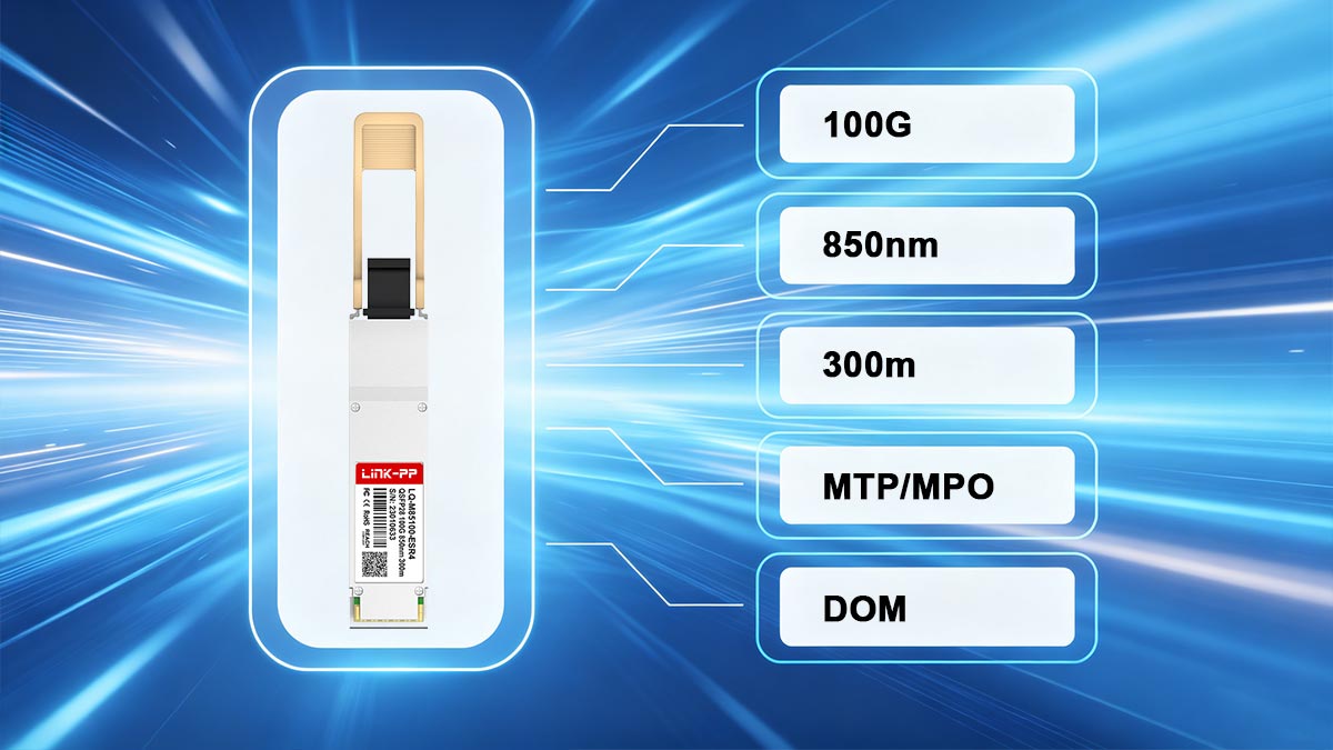
The QSFP28 ESR4 is an extended short-reach 4-channel optical transceiver module designed for high-density 100-Gigabit Ethernet applications. It utilizes the highly compact QSFP28 form factor, meaning it integrates four independent transmit and receive channels operating at 25Gbps per lane.
What sets the ESR4 form factor apart is its enhanced optical power budget, which allows it to push signals much farther than standard short-reach modules. It provides an ideal, cost-effective intermediate solution for data centers that need more distance than standard multi-mode optics can offer, but want to avoid the high cost of single-mode alternatives.
Comparing Core Architecture: QSFP28-ESR4 vs. Standard SR4 Optics
While both transceiver types share the same physical dimensions and rely on a 4-channel VCSEL laser array, their internal optical components differ significantly to achieve different reach capabilities. The ESR4 architecture features higher-quality transmitters and more sensitive receivers, which collectively provide a tighter optical power budget.
The key differences in design and performance metrics between these two optical standards are highlighted in the comparison below.
| Feature / Specification |
QSFP28-SR4
(Standard Short Reach) |
QSFP28-ESR4
(Extended Short Reach) |
| Max Distance (OM3 Fiber) |
Up to 70m |
Up to 200m |
| Max Distance (OM4 Fiber) |
Up to 100m |
Up to 300m |
| Optical Transmitter |
850nm VCSEL Array |
Enhanced 850nm VCSEL Array |
| Receiver Sensitivity |
Standard |
High Sensitivity |
| Primary Use Case |
Intra-rack / Short inter-rack |
Across large data halls / Inter-building |
Primary Network Topologies and Use Cases for Extended Multi-Mode Links
The primary use case for these extended-reach transceivers is connecting core, spine, and leaf switches across massive data center floors where distances exceed 100m. They are heavily utilized in enterprise networks and cloud data centers to bridge separate rows of server racks without deploying expensive single-mode fiber infrastructure.
Additionally, these modules excel in breakout topologies, allowing a single 100G switch port to split into four individual 25G connections over longer distances. This flexibility makes them highly valuable for high-density distribution layers where servers are spread across a wide physical area.
Key Industry Standards and IEEE 802.3bm Protocol Compliance
Reliable multi-vendor interoperability is guaranteed because these transceivers adhere strictly to established international networking protocols. They comply fully with the IEEE 802.3bm electrical interface standards, ensuring predictable performance on any compliant host board.
Furthermore, the mechanical and electrical designs conform to the QSFP28 Multi-Source Agreement (MSA). This strict compliance ensures that the modules are completely hot-pluggable, mechanically secure, and capable of seamless digital diagnostics across diverse hardware platforms.
↘️ Optical and Electrical Specifications of QSFP28-ESR4
The overall reliability and extended reach of a high-speed fiber link depend heavily on its underlying physical parameters. Examining the precise optical and electrical requirements ensures that network hardware operates safely within its design limits while maintaining peak data integrity. These standardized metrics dictate how the hardware transmits light waves and manages electrical power across the system.
Data Rate and Wavelength Architecture
The QSFP28-ESR4 achieves its total 100Gbps throughput by utilizing a parallel design that splits data across four independent lanes. Each of these lanes operates at a precise data rate of 25Gbps using NRZ modulation, allowing the module to handle massive enterprise workloads concurrently.
To transmit this data efficiently over multi-mode fiber, the module relies on a nominal optical wavelength of 850nm. Each lane operates within a strict center wavelength range of 840nm to 860nm, balancing light source efficiency with minimal signal degradation inside the fiber cores.
Transmitter Optical Characteristics and Launch Power
The transmitter side of the QSFP28-ESR4 features a high-performance Vertical-Cavity Surface-Emitting Laser (VCSEL) array. To achieve its extended distance rating, the average launch power (TX Power) per lane is designed to range from a minimum of -4dBm up to a maximum of 4dBm.
Engineers must monitor these average launch power limits to guarantee that the signal can survive long cable runs without degrading. Additionally, the transmitter maintains an optical extinction ratio (ER) of greater than 2dB, ensuring a distinct contrast between the light pulses representing digital ones and zeros.
Receiver Sensitivity and Saturation Thresholds
Equipped with an array of highly sensitive PIN photodiodes, the QSFP28-ESR4 receiver is built to detect incredibly faint light signals returning from long distances. The module delivers an impressive average receive power range (RX Power) of -12dBm to 2.4dBm per lane, which allows it to successfully decode data even after significant signal attenuation.
However, the receiver also features a strict optical saturation threshold to protect its delicate internal components. If the incoming light from an unattenuated short patch cable exceeds these safety limits, it can overwhelm or permanently damage the photodiodes, making it crucial to manage input power levels.
Electrical Interface and Power Consumption Limits
On the host side, the QSFP28-ESR4 connects via a 38-pin edge connector that utilizes a high-speed CAUI-4 electrical interface compliant with IEEE 802.3bm standards. It operates on a standard supply voltage of 3.3V and supports clean electrical signal transitions between the transceiver and the host switch motherboard.
Despite its enhanced optical performance, the module operates efficiently within a maximum power consumption limit of 2.5W. This low power draw minimizes heat generation within high-density network switches, simplifying data center cooling requirements.
↘️ Cable Distance and Media Support for QSFP28-ESR4
Selecting the appropriate optical cabling infrastructure is crucial for achieving maximum transmission distances in high-speed networks. The choice of multi-mode fiber grading directly impacts the signal integrity and the overall physical span of the connection. Understanding these media capabilities ensures efficient network planning and prevents unnecessary deployment costs.
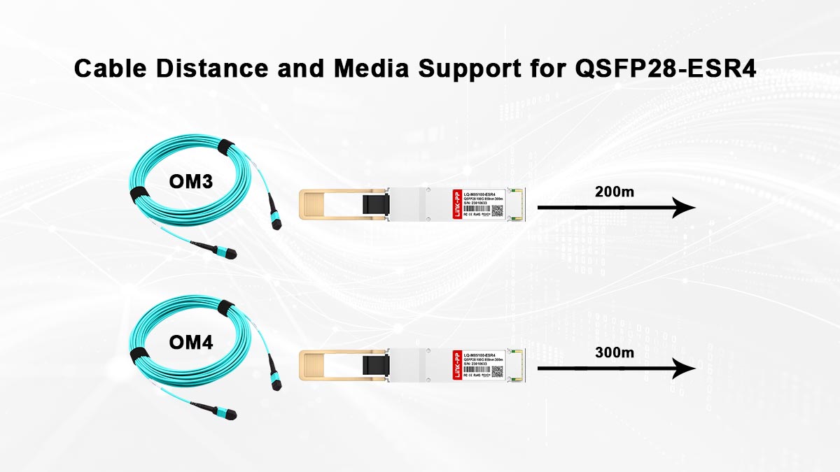
Maximizing Reach up to 200m via OM3 Multi-Mode Fiber
The QSFP28-ESR4 significantly breathes new life into existing legacy multi-mode infrastructure by boosting its standard distance limits. When deployed over standard laser-optimized OM3 cabling, this transceiver extends high-speed data transmission way beyond the traditional boundaries of short-reach modules.
The key deployment specifications for using this transceiver with OM3 fiber include the following points:
- Maximum Reach: Achieves reliable data transmission up to 200m.
- Fiber Core Diameter: Utilizes standard 50-micron multi-mode fiber cores.
- Modal Bandwidth: Requires a minimum effective modal bandwidth of 2000 MHz·km.
- Cost Efficiency: Eliminates the need to replace existing OM3 building backbones.
Extending Link Boundaries to 300m using OM4 Cabling Infrastructure
For newer data center builds or targeted upgrades, pairing the QSFP28-ESR4 with high-grade OM4 fiber unlocks its ultimate distance potential. This combination provides the maximum possible reach over multi-mode media, making it an excellent alternative to pricey single-mode setups.
The following guidelines highlight the specific performance benefits of an OM4 cabling setup:
- Maximum Reach: Pushes transmission boundaries up to 300m.
- Modal Bandwidth: Leverages an upgraded bandwidth of 4700 MHz·km.
- Application Scope: Perfect for connecting distant leaf-spine switch layouts.
- Future Proofing: Maintains infrastructure compatibility for future speed upgrades.
Calculating Total Insertion Loss Budgets for Multi-Connector Channels
As light travels through a fiber channel, it naturally loses strength at every patch panel, splice, and connector mating point. When planning a QSFP28-ESR4 deployment across a data hall, engineers must mathematically calculate these losses to ensure the link operates reliably.
Several crucial elements must be accounted for when verifying the total channel power budget:
- Maximum Budget: Total allowable channel insertion loss is limited to 1.9dB.
- Fiber Attenuation: Account for roughly 3.5dB of loss per kilometer at 850nm.
- Connection Loss: MPO connectors typically add 0.35dB to 0.75dB of loss each.
- Safety Margin: Keep a baseline power buffer to accommodate component aging.
Minimum Cable Length Requirements and Avoiding Receiver Saturation Issues
While extending the maximum reach is the primary goal, network operators must also pay attention to the shortest permissible fiber runs. Because the QSFP28-ESR4 features highly optimized, high-power transmitters, using incredibly short cables without proper planning can degrade performance.
The fundamental rules for avoiding optical receiver overdrive include the following parameters:
- Saturation Risk: Avoid plugging high-power ports directly together with short patch cords.
- Signal Protection: Prevent permanent damage to the highly sensitive PIN photodiodes.
- Attenuation Solution: Use inline optical attenuators if ultra-short testing is required.
↘️ Pinout Configuration and Interface Dynamics of QSFP28-ESR4
Establishing a reliable connection requires perfect alignment between the physical optical connector and the internal electrical routing of the host switch. The physical interface configuration dictates how optical signals are cleanly mapped onto hardware circuitry without data corruption. Examining these pin assignments and hardware interfaces ensures complete compatibility during high-density deployments.
MPO/MTP-12 Connector Interface and 12-Fiber Optical Lane Assignments
The QSFP28-ESR4 utilizes an industry-standard male MPO/MTP-12 optical connector receptacle to interface with multi-mode patch cables. This interface uses a specific 12-fiber alignment where only the outer lanes are active, leaving the center fibers unused.
Specifically, the four leftmost fibers are dedicated to transmitting optical signals, while the four rightmost fibers handle the receiving channels. The central four positions remain physically empty, a standardized optical layout that ensures seamless mating with standard multi-mode trunk cables.
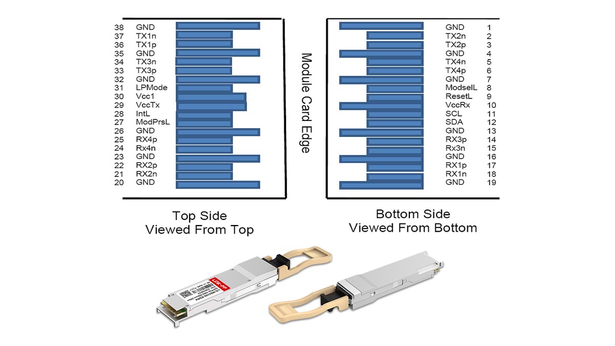
Hardware Pin Mapping for 38-Pin Hot-Pluggable Edge Connectors
On the electrical side, the QSFP28-ESR4 features a standard 38-pin gold-finger edge connector that plugs directly into the host switch port. This layout is strictly governed by the QSFP28 Multi-Source Agreement (MSA) to guarantee uniform physical dimensions and electrical spacing.
The 38 pins are split across the top and bottom rows of the module's printed circuit board to optimize signal density. This hardware mapping provides dedicated lines for high-speed data, power supply grounding, and essential low-speed control communications.
Transmit (TX) and Receive (RX) Differential Signal Pair Allocation
To maintain data integrity at 100G speeds, the QSFP28-ESR4 relies on high-speed differential signaling for its transmit and receive paths. The pinout allocates four differential pairs for transmission (TX1n/TX1p through TX4n/TX4p) and another four pairs for receiving data (RX1n/RX1p through RX4n/RX4p).
These differential pairs are physically isolated from each other by interspersed power supply ground pins. This specific physical shielding minimizes electromagnetic interference and crosstalk, ensuring clean electrical waveforms enter and exit the transceiver module.
High-Speed Electrical Interface Controls and Low-Speed Management Signals
Beyond high-speed data delivery, the QSFP28-ESR4 edge connector features vital low-speed pins used for real-time hardware status management. These include critical control signals such as ModSelL (Module Select), ResetL (Module Reset), and LPMode (Low Power Mode).
Additionally, a dedicated two-wire serial interface clock (SCL) and data line (SDA) allow the host system to talk directly to the transceiver. Through these pins, the switch reads diagnostic telemetry and verifies hardware compatibility details instantly.
↘️ Digital Optical Monitoring (DOM) Functions in QSFP28-ESR4
Maintaining a highly reliable network infrastructure requires constant visibility into the operating health of active hardware components. Integrated diagnostic tools allow network administrators to track vital optical and electrical parameters in real time without disrupting live data traffic. Utilizing these built-in telemetry features helps isolate physical layer issues quickly and ensures maximum network uptime.
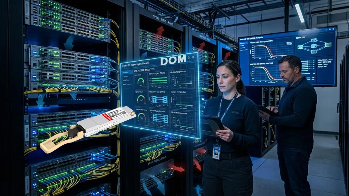
Real-Time Monitoring of Transmit and Receive Optical Power
The QSFP28-ESR4 includes specialized internal circuitry that tracks the optical power levels across all four independent channels. This monitoring is vital for verifying that the lasers are launching strong signals and that the receiving photodiodes are catching healthy light waves.
Network engineers can continuously check these specific optical metrics through the switch interface:
- TX Power Levels: Measures the exact light output from each individual VCSEL channel.
- RX Power Levels: Checks the incoming light strength after it spans the multi-mode fiber.
- Link Loss Detection: Helps identify unexpected fiber bends or dirty optical connectors.
- Degradation Tracking: Spots failing laser diodes before they cause packet drop issues.
Internal Transceiver Temperature and Voltage Diagnostics
Beyond tracking raw light levels, the QSFP28-ESR4 constantly measures its own internal environmental operating conditions. Because component overheating and voltage fluctuations can drastically lower the lifespan of optical modules, these onboard sensors act as a critical safety net.
The core environmental parameters monitored by the transceiver include the following items:
- Internal Temperature: Measures the live operating temperature inside the module casing.
- Supply Voltage: Monitors the incoming 3.3V electrical power feed from the host switch.
- Laser Bias Current: Tracks the exact drive current being pushed into the VCSEL array.
- Component Health: Helps detect power supply instability or overheating in switch chassis slots.
Setting Threshold Alerts for Proactive Link Failure Prevention
To automate network maintenance, the QSFP28-ESR4 utilizes pre-programmed factory thresholds to flag abnormal behavior. When any internal measurement drifts outside safe operating boundaries, the module triggers immediate system alarms.
The module categorizes these system alerts into two distinct diagnostic levels:
- High/Low Warning Flags: Notifies operators when parameters drift near dangerous operating limits.
- High/Low Alarm Flags: Signals immediate out-of-spec conditions that could ruin hardware.
- Proactive Maintenance: Allows engineers to hot-swap fading modules during scheduled maintenance windows.
- Port Protection: Enables host switches to shut down ports automatically during severe over-voltage events.
Accessing DOM/DDM Data via I²C Two-Wire Serial Interface
All the real-time diagnostic telemetry gathered by the QSFP28-ESR4 is stored in organized memory registers inside the module's EEPROM. The host system pulls this data seamlessly using standard management software protocols.
The host board extracts and translates this internal telemetry using the following mechanisms:
- I²C Serial Interface: Communicates over a simple two-wire bus using clock and data lines.
- SFF-8636 Compliance: Follows standard memory map layouts for uniform data reading.
- Real-Time Polling: Allows the switch OS to update diagnostic metrics every few seconds.
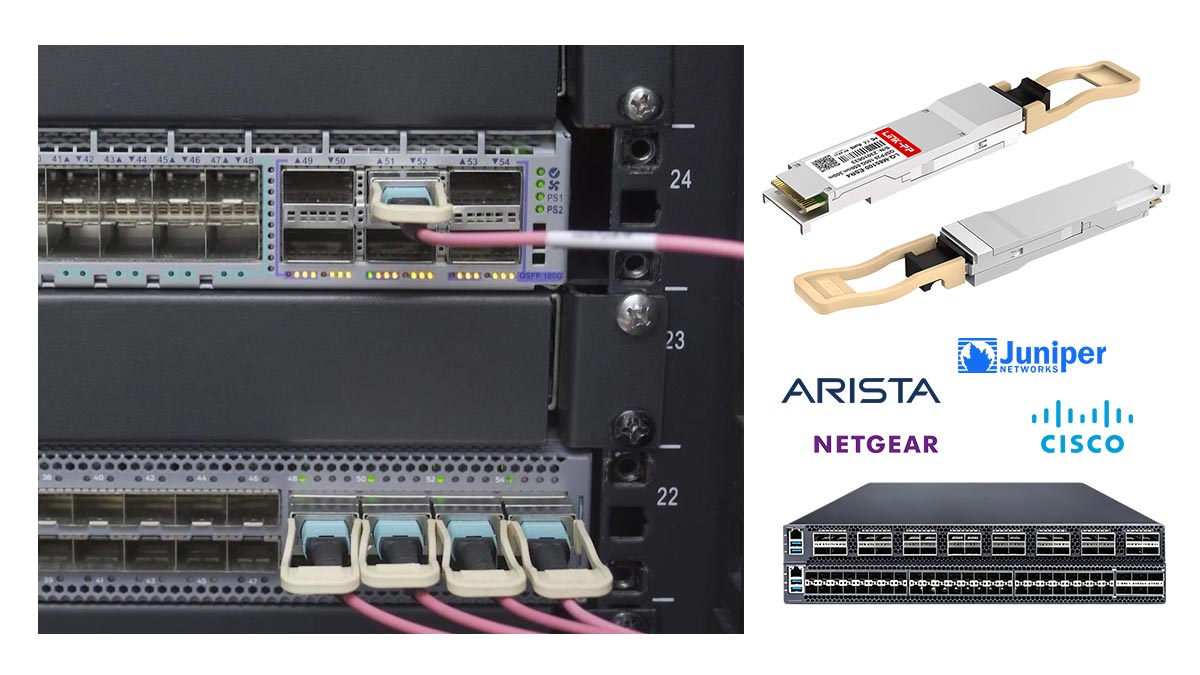
↘️ Network Compatibility and Host Interoperability Specs for QSFP28-ESR4
Deploying new optical hardware into a data center requires seamless integration with existing multi-vendor switch platforms. Ensuring software compatibility and reliable error-correction protocols prevents link dropouts and packet loss across the network fabric. Examining the underlying compatibility specifications guarantees that these modules are recognized properly and communicate flawlessly with host devices.
Multi-Vendor EEPROM Coding and Host Board Register Mapping
To ensure broad system recognition, the QSFP28-ESR4 features an onboard EEPROM programmed with vendor-specific configuration data. This internal memory chip holds essential information like part numbers, serial codes, and firmware versions that the host switch reads instantly upon insertion.
When plugged into a network port, the host board maps these internal EEPROM registers to verify hardware authenticity. Proper coding ensures that major switch brands accept the transceiver without triggering annoying "unsupported module" security alerts or software port lockouts.
Host-Side Forward Error Correction (FEC) Requirements for Error-Free Links
Achieving an error-free transmission over extended multi-mode fiber runs requires the host switch to actively enable Forward Error Correction. The QSFP28-ESR4 relies on host-side KR4-FEC (Clause 91) to detect and correct random bit errors that occur across long distances.
By processing data through the host's FEC engine, the system can reliably clean up signal distortions caused by modal dispersion in the fiber. This hardware cooperation allows the link to maintain a clean, stable connection even when pushing data to its absolute distance boundaries.
Backward Interoperability and Link Negotiation with Standard 100G-SR4 Optics
A major operational benefit of the QSFP28-ESR4 is its complete backward compatibility with standard short-reach multi-mode optics. Because it shares the exact same 850nm wavelength and NRZ modulation scheme, it can connect directly to a standard 100G-SR4 module on the opposite end of a link.
During initial link negotiation, the two transceivers establish a seamless connection without needing manual configuration. However, network operators must remember that the maximum transmission distance will be limited to the standard SR4 specifications when interconnected this way.
QSFP28 Multi-Source Agreement (MSA) Electrical Interface Compliance
Complete hardware interoperability is guaranteed because the QSFP28-ESR4 strictly adheres to the international Multi-Source Agreement guidelines. These physical and electrical standards ensure that the module fits into any standard-compliant cage regardless of the switch vendor.
The electrical interface lines are fine-tuned to match MSA requirements for impedance, timing tolerances, and voltage levels. This uniform compliance simplifies data center procurement, allowing network managers to confidently mix and match hardware brands without risking stability issues.
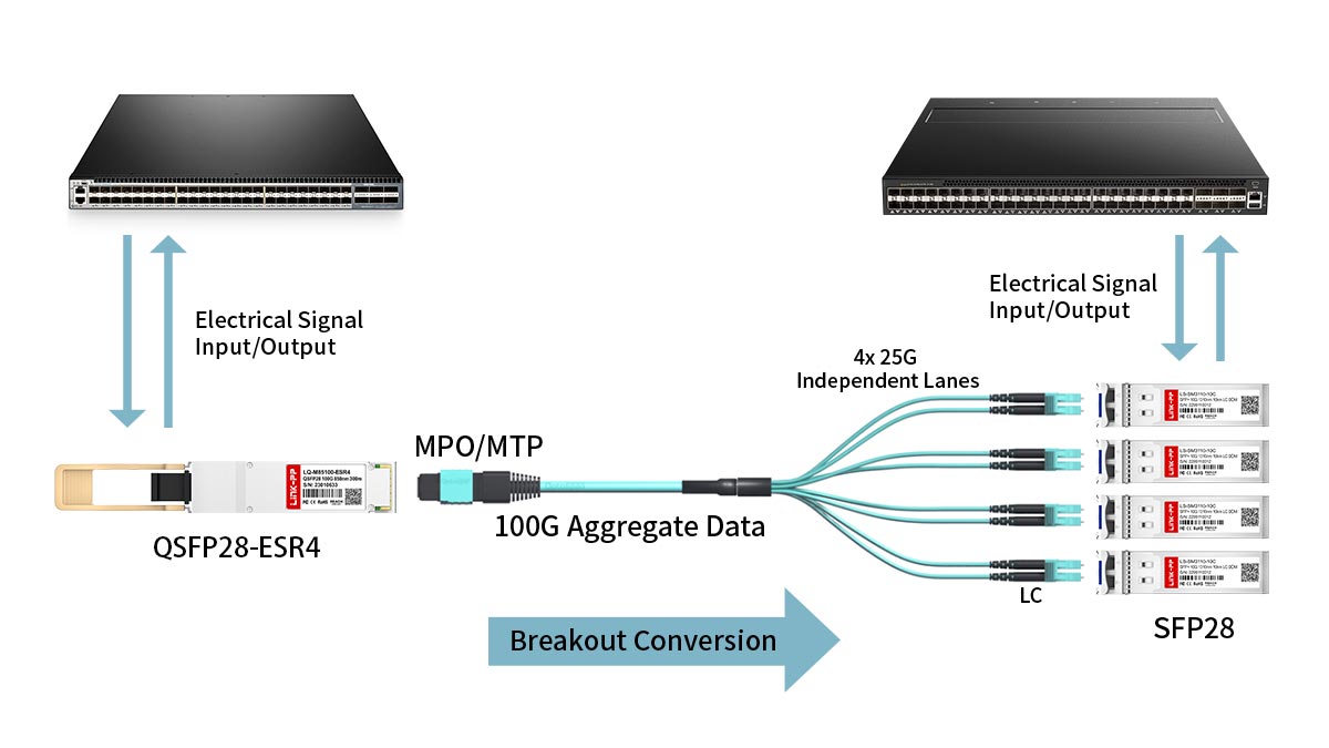
↘️ QSFP28-ESR4 Breakout Specifications for 4x25G Multi-Mode Links
Maximizing port density and improving cabling flexibility are core goals when designing modern high-speed data center fabrics. Breakout configurations allow a single high-bandwidth switch port to communicate directly with multiple lower-speed devices over extended distances. Implementing these specialized multi-channel splitting configurations enables highly efficient hardware utilization without wasting valuable rack space.
Channelization Settings for Splitter Configurations on Host Ports
To successfully deploy a breakout link, the host switch operating system must be manually or automatically configured to split the port's bandwidth. The system configuration changes the single 100G logical channel of the QSFP28-ESR4 into four individual 25G channels.
This process, often called channelization, splits the single physical port into four distinct sub-ports within the switch software. Once enabled, the switch treats each lane of the QSFP28-ESR4 as an independent 25G Ethernet interface with its own MAC address and routing rules.
MPO-12 to 4x LC Duplex Harness Cable Spec Requirements
Connecting a split port to individual servers or downstream switches requires a specialized MPO-12 to 4x LC Duplex breakout harness cable. The MPO end plugs directly into the QSFP28-ESR4, while the four duplex LC connectors attach to standard 25G SFP28 transceivers.
This fiber harness must match the exact multi-mode grading, such as OM3 or OM4, used throughout the rest of the link infrastructure. Additionally, proper polarity mapping within the optical cable is critical to ensure the transmit lanes on the 100G side align perfectly with the receive lanes on the 25G side.
Insertion Loss and Power Budget Allocation in Breakout Topologies
Splitting a single optical link into four separate paths introduces extra physical connection points that can degrade light signals. When utilizing the QSFP28-ESR4 in breakout mode, network planners must carefully calculate the accumulation of insertion loss caused by the additional LC mating sleeves.
Because the total allowable channel loss remains tightly capped, every connector pair reduces the remaining fiber length budget. Using high-quality, low-loss breakout cassettes and premium harness cables is essential for keeping the total attenuation well within safe operating limits.
Managing Maximum Transmission Distances in 25G Extended Reach Modes
When running a breakout topology, the maximum achievable distance depends heavily on the specifications of the optics on both ends of the link. The QSFP28-ESR4 provides enhanced transmit power, but it must be paired with compatible 25G transceivers to hit its full distance potential.
If connected to standard short-reach 25G SFP28 modules, the total link distance might be limited by the weaker receiver sensitivity of the smaller modules. To ensure a stable 200-meter run on OM3 or a 300-meter run on OM4, the downstream 25G transceivers must also support extended-reach specifications.
↘️ Summary of QSFP28-ESR4 Specifications for Extended Reach MMF Links
The QSFP28-ESR4 optical transceiver provides a highly efficient and economical solution for data centers needing to bridge the gap between short-range and long-haul links. By maximizing the capabilities of existing multi-mode fiber infrastructure, it allows network operators to scale up to 100G speeds without the massive capital expense of deploying single-mode fiber.
A quick review of its core technical capabilities highlights why this module is so valuable for modern high-density networks:
- Extended Multi-Mode Reach: Spans up to 200m on OM3 and 300m on OM4 fiber.
- Optimized Optical Budget: Delivers a reliable -4 to 4dBm TX power range.
- High Receiver Sensitivity: Captures faint signals down to a wide -12dBm RX power limit.
- Low Power Consumption: Operates efficiently under a tight 2.5W power budget.
- Flexible Breakout Modes: Supports seamless 4x25G channelization over MPO cabling.
- Full QSFP28 MSA Compliance: Guarantees universal hot-pluggable interoperability on standard host boards.
When you are ready to upgrade your data center infrastructure with high-performance networking hardware, choosing premium, fully tested optics is critical. You can explore a wide selection of reliable, multi-vendor compatible transceiver modules by visiting the LINK-PP Official Store today to find the perfect match for your high-speed link requirements.


