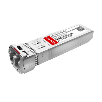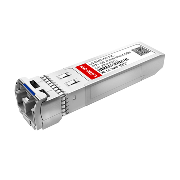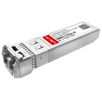
Finisar FTLX1471D3BCL is a 10Gb/s SFP+ optical transceiver designed for high-speed Ethernet and Fibre Channel connectivity over Single Mode Fiber. As 10G network deployments continue to span data centers, enterprise networks, and longer-distance infrastructure, selecting an optical module based on accurate technical specifications has become increasingly important. Factors such as wavelength, transmission distance, fiber type, connector, and host-port requirements can directly affect link performance and interoperability.
The FTLX1471D3BCL datasheet provides the technical foundation for evaluating this module, while FTLX1471D3BCL compatibility determines whether it can operate correctly with a specific network platform and optical link. However, an SFP+ form factor alone does not guarantee compatibility. The host device, 10G standard, Single Mode Fiber, 1310nm optical path, and transceiver recognition requirements should all be considered before deployment.
This guide examines the key information needed to understand and evaluate FTLX1471D3BCL, including:
- Core FTLX1471D3BCL datasheet specifications
- Optical, electrical, mechanical, and diagnostic characteristics
- Host, fiber, connector, and protocol compatibility
- Deployment verification and troubleshooting considerations
- Differences from similar 10G SFP+ solutions
Together, these points provide a practical reference for determining whether FTLX1471D3BCL matches a specific 10G network requirement.
🚩 What Is Finisar FTLX1471D3BCL?
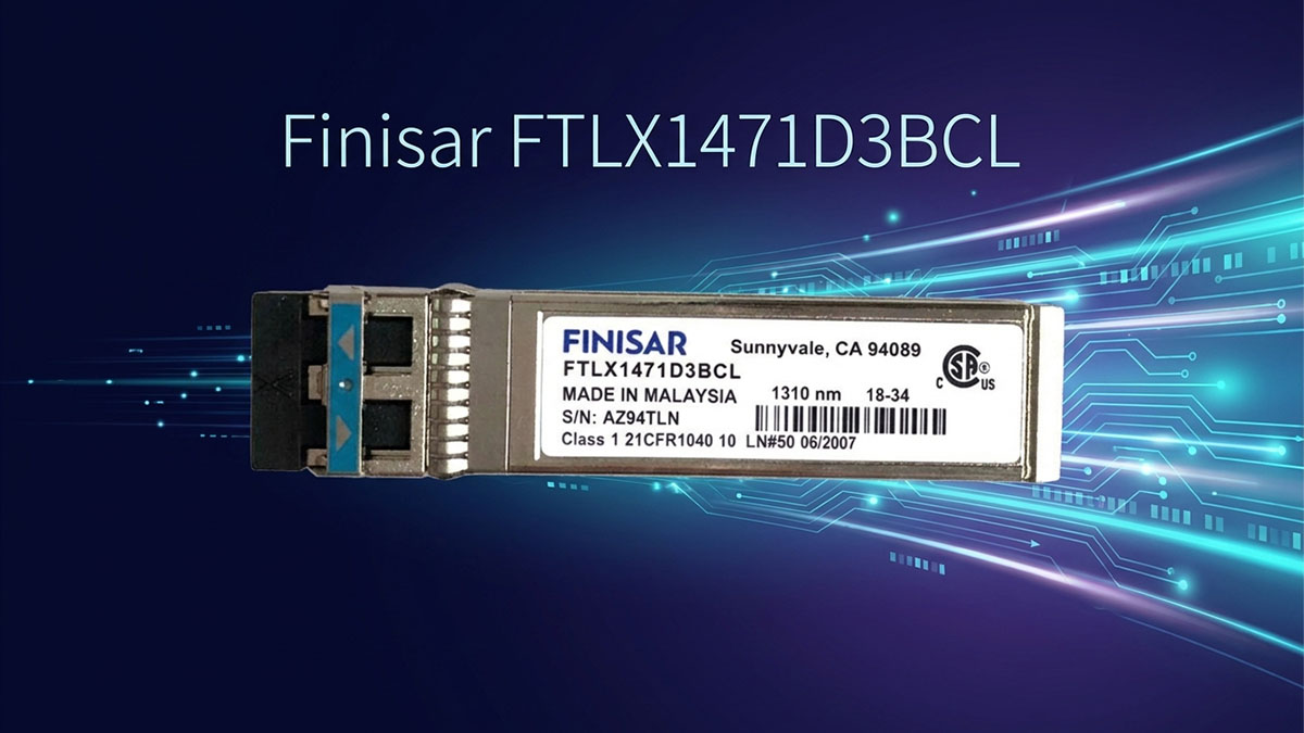
Finisar FTLX1471D3BCL is a 10Gb/s SFP+ optical transceiver designed for 10G Ethernet transmission over Single Mode Fiber at a nominal wavelength of 1310nm. It supports 10GBASE-LR/LW applications with a reach of up to 10km and also supports 1200-SM-LL-L 10G Fibre Channel applications. Its SFP+ form factor, duplex LC interface, and digital diagnostic capabilities make it suitable for longer-reach 10G network links where Single Mode Fiber is required.
FTLX1471D3BCL Product Positioning
FTLX1471D3BCL is positioned as a long-reach 10G optical module rather than a short-range multimode SFP+. Its main characteristics are centered on 10Gb/s operation, 1310nm transmission, Single Mode Fiber, and 10km reach.
Key aspects of its product positioning include:
- 10Gb/s SFP+ transceiver: Designed for high-speed network equipment using an SFP+ optical interface.
- 10GBASE-LR/LW support: Intended for 10G Ethernet applications requiring longer optical reach.
- 10km transmission distance: Suitable for links extending beyond typical short-reach 10G multimode deployments.
- 1310nm wavelength: Uses a 1310nm optical channel for transmission over Single Mode Fiber.
- Single Mode Fiber: Designed for SMF infrastructure rather than 850nm multimode fiber.
- DFB laser transmitter: Uses an uncooled 1310nm DFB laser architecture.
- Fibre Channel support: The specification also identifies 1200-SM-LL-L 10G Fibre Channel as a supported application.
- SFP+ form factor: Provides a compact, hot-pluggable optical interface for compatible network equipment.
These characteristics are important when evaluating FTLX1471D3BCL compatibility because the module must match both the optical infrastructure and the host platform. A compatible SFP+ port alone is not sufficient if the device or fiber link does not support the required 10G optical standard.
FTLX1471D3BCL Key Parameters at a Glance
The most useful way to establish the technical identity of FTLX1471D3BCL is to compare its primary parameters in one place. The following specifications provide the baseline for subsequent compatibility and deployment analysis.
| Parameter | FTLX1471D3BCL |
|---|---|
| Form Factor | SFP+ |
| Data Rate | 10Gb/s |
| Wavelength | 1310nm |
| Maximum Reach | 10km |
| Fiber Type | Single Mode Fiber |
| Connector | Duplex LC |
| Laser Type | Uncooled DFB |
| Application | 10GBASE-LR/LW, 1200-SM-LL-L |
| Operating Temperature | -5°C to 70°C |
| Digital Diagnostics | Supported |
These parameters show that FTLX1471D3BCL is primarily intended for 10G long-reach SMF connectivity. In particular, the combination of 1310nm wavelength, Single Mode Fiber, and 10km reach distinguishes it from 10GBASE-SR modules that typically use 850nm optics and multimode fiber.
🚩 Finisar FTLX1471D3BCL Datasheet Specifications
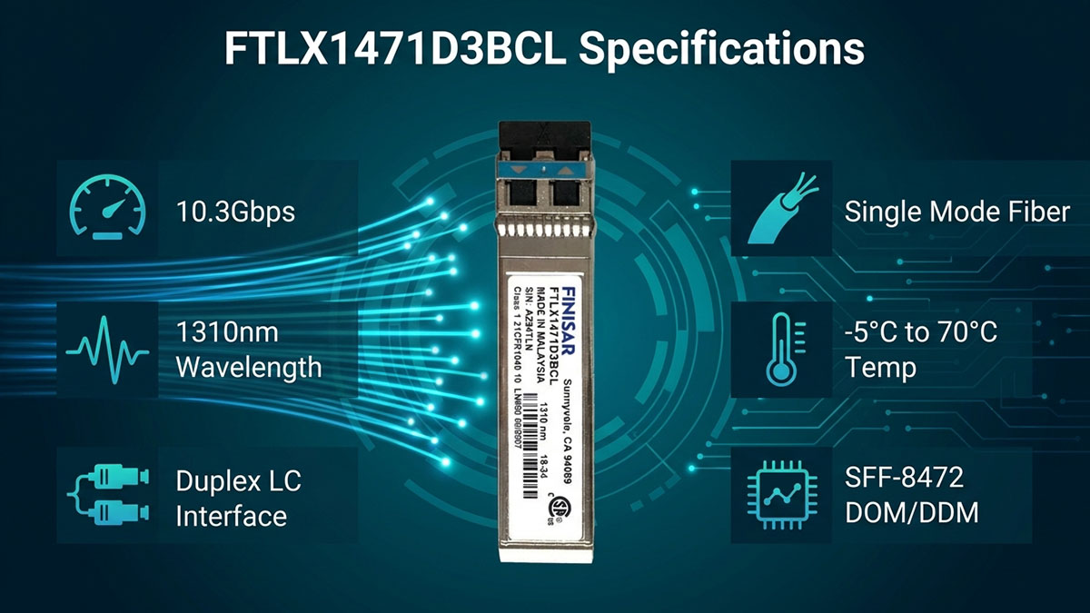
The FTLX1471D3BCL datasheet defines this module as a 10Gb/s, 10km Single Mode Fiber SFP+ transceiver operating at 1310nm. Its specifications cover optical performance, electrical interface requirements, environmental conditions, standards compliance, and digital diagnostics, providing the technical baseline for deployment and compatibility evaluation.
Optical Specifications
The optical characteristics of FTLX1471D3BCL are centered on 1310nm transmission over Single Mode Fiber with a maximum specified link length of 10km. The module uses an uncooled 1310nm DFB laser and a limiting receiver, making these parameters particularly important when matching the module with the optical infrastructure and equipment at the opposite end.
Key optical specifications include:
- Nominal wavelength: 1310nm
- Optical wavelength range: 1260nm to 1355nm for the transmitter
- Maximum supported link length: 10km
- Fiber type: Single Mode Fiber
- Transmitter: Uncooled 1310nm DFB laser
- Optical connector: Duplex LC
- Receiver type: Limiting receiver
- Receiver sensitivity: -12.6dBm OMA at 10.3Gb/s
- Stressed receiver sensitivity: -10.3dBm OMA at 10.3Gb/s
- Bit error ratio: 10^-12 under the specified test conditions
These values explain why FTLX1471D3BCL belongs to the 10GBASE-LR/LW class rather than the short-reach 10GBASE-SR class. When evaluating FTLX1471D3BCL compatibility, the optical wavelength, fiber type, link distance, and optical power conditions should therefore be checked together rather than independently.
Data Rate and Ethernet Standards
FTLX1471D3BCL supports a bit-rate range of 9.95Gb/s to 10.5Gb/s and is specified for 10GBASE-LR/LW Ethernet applications. The datasheet also identifies compatibility with 1200-SM-LL-L 10G Fibre Channel, so the module is not limited to a single 10G application.
The main standards and operating characteristics are:
- Bit-rate range: 9.95Gb/s to 10.5Gb/s
- 10G Ethernet: 10GBASE-LR/LW
- Fibre Channel: 1200-SM-LL-L 10G Fibre Channel
- Ethernet standard: IEEE 802.3ae
- SFP+ electrical standards: SFF-8431 and SFF-8432
- Maximum specified reach: 10km over Single Mode Fiber
This distinction matters for compatibility because the label "10G SFP+" describes the physical module category, not every protocol or optical implementation that a host port can support. The host equipment should support the intended 10G application in addition to accepting the SFP+ form factor.
Electrical Interface and Power Requirements
The FTLX1471D3BCL electrical interface is designed around a single 3.3V power supply and an SFP+ host interface. The module uses a limiting receiver, which is an important consideration for host-board designs incorporating an EDC PHY. Finisar specifically notes that EDC PHY settings should follow the PHY manufacturer's recommendations when interoperating with a limiting-receiver SFP+ module.
Important electrical characteristics include:
- Single 3.3V power supply.
- SFF-8431-compliant electrical interface.
- Hot-pluggable SFP+ footprint.
- Limiting receiver electrical interface.
- Differential CML electrical inputs and outputs.
- Power dissipation below 1W.
- Host-side EDC PHY interoperability may require manufacturer-recommended settings.
The electrical specifications are especially relevant when FTLX1471D3BCL is evaluated for compatibility with a specific switch, router, server adapter, or other host platform. Optical specifications can match while host-side electrical or PHY behavior still prevents a link from operating correctly.
Digital Diagnostic Monitoring
FTLX1471D3BCL includes built-in digital diagnostic functions that are accessed through a 2-wire serial interface specified by SFF-8472. This allows compatible host equipment to monitor important operating conditions and provides additional information when troubleshooting an optical link.
The diagnostic interface is useful for monitoring parameters such as:
- Module temperature.
- Laser bias current.
- Transmitted optical power.
- Received optical power.
- Other module diagnostic information supported through the SFF-8472 interface.
DOM/DDM information can help determine whether a link problem is related to optical power, module operating conditions, or another part of the network path. However, the host platform must also support reading and interpreting the module's diagnostic information correctly.
Mechanical and Environmental Specifications
The mechanical and environmental specifications define where FTLX1471D3BCL can physically operate and under what temperature conditions. The datasheet specifies an SFP+ footprint, duplex LC interface, commercial operating temperature range of -5°C to 70°C, and storage temperature range of -40°C to 85°C.
The primary deployment-related specifications are:
- Form factor: SFP+
- Optical connector: Duplex LC
- Operating case temperature: -5°C to 70°C
- Storage temperature: -40°C to 85°C
- Power dissipation: <1W
- Compliance: RoHS-6
- Laser classification: Class 1 laser product
The commercial temperature range should be considered before deployment in outdoor cabinets, industrial environments, or equipment rooms without controlled temperature. Likewise, the SFP+ form factor and LC interface must match the physical design of the host and fiber infrastructure, while compliance requirements may matter for broader equipment qualification.
🚩 Finisar FTLX1471D3BCL Compatibility
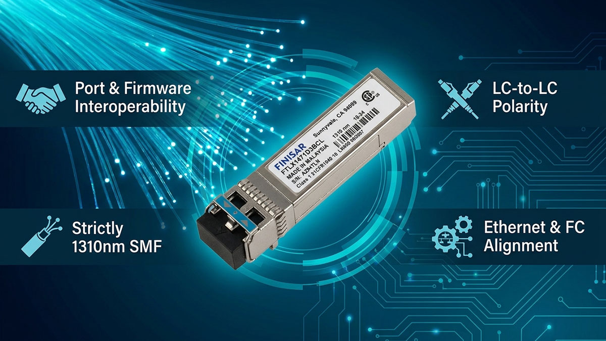
Finisar FTLX1471D3BCL compatibility depends on more than whether a device has an SFP+ port. The host platform, supported 10G standard, Single Mode Fiber, 1310nm optical path, connector configuration, and electrical interface must all align with the module's specifications. The datasheet identifies FTLX1471D3BCL as a 10Gb/s SFP+ transceiver for 10GBASE-LR/LW and 1200-SM-LL-L 10G Fibre Channel, with a maximum link length of 10km over Single Mode Fiber.
FTLX1471D3BCL Host Port Compatibility
FTLX1471D3BCL can be considered host-compatible when the network device provides a suitable SFP+ interface and supports the module's intended application and electrical characteristics. A physical SFP+ slot establishes the basic mechanical interface, but it does not by itself confirm successful optical operation.
When checking a switch, router, server adapter, or storage platform, verify:
- Port type: Confirm that the port is designed for SFP+ rather than SFP, QSFP+, or another interface.
- Data rate: Verify support for 10Gb/s operation within the module's specified 9.95Gb/s to 10.5Gb/s range.
- Application support: Check whether the host supports 10GBASE-LR/LW or the intended Fibre Channel application.
- Transceiver policy: Determine whether the platform restricts supported optical modules based on vendor identification or EEPROM information.
- Electrical interface: Confirm compatibility with the SFP+ electrical interface and host-side PHY implementation.
- Diagnostics: If DOM/DDM monitoring is required, verify that the host can read the module's SFF-8472 diagnostic information.
The electrical interface also deserves particular attention in host-board designs. Finisar describes FTLX1471D3BCL as a limiting module and notes that systems using an EDC PHY should follow the PHY manufacturer's recommended settings for interoperability with a limiting-receiver SFP+ module.
FTLX1471D3BCL Fiber Compatibility
FTLX1471D3BCL is designed for Single Mode Fiber at 1310nm, with a maximum specified link length of 10km. Therefore, the fiber plant should be evaluated together with the module's wavelength, reach, and optical characteristics rather than simply being identified as a generic "10G fiber" connection.
The main fiber compatibility checks are:
- Fiber type: Single Mode Fiber (SMF).
- Operating wavelength: 1310nm-class transmission.
- Link distance: No more than the specified 10km maximum under the applicable link conditions.
- Optical path: Verify that attenuation, connectors, patch panels, and splices remain within the available optical budget.
- Opposite-end optic: Confirm that the remote transceiver uses a compatible 10G optical architecture.
- Fiber plant condition: Inspect connectors and patch cords for contamination, damage, or excessive loss.
This also distinguishes FTLX1471D3BCL from 10GBASE-SR modules, which use a fundamentally different short-reach multimode architecture. The FTLX1471D3BCL datasheet specifically identifies Single Mode Fiber and 10km operation as part of its intended 10G Ethernet deployment.
FTLX1471D3BCL Connector Compatibility
FTLX1471D3BCL uses a duplex LC optical connector, so the physical fiber connection should provide the appropriate LC interface and correct transmit/receive polarity.
Before connecting the module, check:
- LC duplex connector availability at both ends.
- Correct Tx-to-Rx and Rx-to-Tx fiber polarity.
- Compatibility of LC patch cords with the installed Single Mode Fiber.
- Cleanliness of the LC connector end faces.
- Correct patch-panel or optical-distribution-panel routing.
A matching LC connector only confirms the physical connection. It does not establish complete optical compatibility, because wavelength, fiber type, reach, and the remote transceiver's specifications must also match.
FTLX1471D3BCL Protocol Compatibility
FTLX1471D3BCL is specified for 10GBASE-LR/LW 10G Ethernet and 1200-SM-LL-L 10G Fibre Channel applications. It also complies with SFF-8431, SFF-8432, and IEEE 802.3ae requirements identified in the product specification.
Protocol compatibility should therefore be checked at the application level:
- 10G Ethernet: Verify that the host port supports the intended 10GBASE-LR/LW application.
- 10G Fibre Channel: Confirm that the storage or Fibre Channel platform supports the specified 1200-SM-LL-L application.
- Physical interface: Confirm SFP+ electrical and mechanical compatibility.
- Remote endpoint: Ensure that the optic at the opposite end supports a compatible standard and optical interface.
- Platform configuration: Check whether software or firmware configuration is required to enable the intended port mode.
This distinction is important because SFP+ describes the module form factor, not universal protocol compatibility. Two modules can share the same SFP+ footprint while differing in wavelength, fiber type, reach, or application support. For FTLX1471D3BCL, successful deployment requires these characteristics to align across the complete link.
🚩 How to Check FTLX1471D3BCL Compatibility Before Deployment
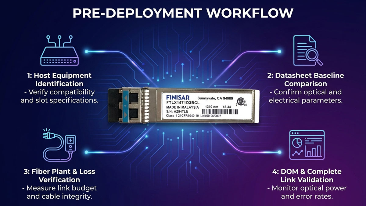
Checking FTLX1471D3BCL compatibility before deployment requires a complete link-level verification rather than simply confirming that the host has an SFP+ slot. The most important checks are the host interface, supported 10G application, Single Mode Fiber, 1310nm optical path, 10km reach, connector configuration, and module diagnostic behavior. The Finisar specification identifies FTLX1471D3BCL as a 10Gb/s SFP+ transceiver supporting 10GBASE-LR/LW and 1200-SM-LL-L 10G Fibre Channel, with a maximum link length of 10km.
Step 1: Identify the Host Equipment and Port
The first step is to identify the exact host device and confirm that its optical port supports the operating characteristics required by FTLX1471D3BCL. A physical SFP+ slot establishes the basic form-factor requirement, but platform-specific support must also be verified.
Check the host equipment for:
- Device model: Record the exact switch, router, server adapter, storage device, or other host model.
- Port type: Confirm that the target interface is an SFP+ port.
- Supported data rate: Verify support for 10Gb/s operation.
- Supported optical standards: Check whether the port supports 10GBASE-LR/LW or the intended Fibre Channel application.
- Transceiver restrictions: Determine whether the platform has vendor-specific module recognition or coding requirements.
- Firmware requirements: Check whether a particular firmware version is required for the optical interface.
This step prevents a common compatibility mistake: assuming that every 10G SFP+ port accepts every 10G SFP+ optical module. FTLX1471D3BCL has a specific electrical and optical implementation, including a limiting receiver, so host-side interoperability should be considered as part of the validation process.
Step 2: Compare the Host Requirements With the Datasheet
After identifying the host port, compare its documented requirements directly with the FTLX1471D3BCL datasheet. This comparison should focus on parameters that can directly affect interoperability rather than on the SFP+ form factor alone.
The most important comparison points are:
- Data rate: FTLX1471D3BCL supports 9.95Gb/s to 10.5Gb/s.
- Optical standard: 10GBASE-LR/LW for Ethernet or 1200-SM-LL-L for 10G Fibre Channel.
- Wavelength: 1310nm-class Single Mode Fiber operation.
- Maximum reach: 10km.
- Fiber type: Single Mode Fiber.
- Connector: Duplex LC.
- Electrical interface: SFP+ interface compliant with the applicable SFF specifications.
- Diagnostics: Digital diagnostics through the SFF-8472 2-wire serial interface.
A parameter-by-parameter comparison is more reliable than matching product names. If the host specifies a different optical standard, fiber type, or operating range, the module should not be treated as automatically compatible simply because both products are described as 10G SFP+.
Step 3: Verify the Fiber Link
The fiber infrastructure must match the optical characteristics of FTLX1471D3BCL. The module is designed for 1310nm transmission over Single Mode Fiber and supports a maximum specified link length of 10km.
Before deployment, verify:
- Fiber type: Confirm that the installed link uses Single Mode Fiber.
- Wavelength path: Ensure the optical infrastructure is appropriate for 1310nm operation.
- Distance: Measure or determine the complete fiber path and keep it within the 10km specified maximum.
- Optical loss: Account for fiber attenuation, connectors, patch panels, and splices.
- Remote optic: Confirm that the transceiver at the opposite end provides a compatible optical interface.
- Fiber condition: Inspect connectors and patch cords for contamination, damage, or excessive insertion loss.
The complete optical path matters because a module can meet its own specifications while the installed fiber infrastructure introduces excessive loss. Therefore, reach should be evaluated together with the actual optical budget rather than treated as an independent distance number.
Step 4: Confirm Module Recognition and DOM Support
Once the physical and optical requirements have been verified, confirm that the host can recognize FTLX1471D3BCL and, where required, read its diagnostic information. The module provides digital diagnostics through a 2-wire serial interface specified by SFF-8472.
The verification process should include:
- Insert the module into the host SFP+ port.
- Confirm that the host identifies the transceiver correctly.
- Check the reported module information and optical parameters.
- Verify that DOM/DDM information is available when the platform supports it.
- Check temperature, laser bias, transmitted optical power, and received optical power where supported.
- Investigate vendor-specific recognition or coding restrictions if the module is not detected.
DOM information is particularly useful during initial validation because it can provide evidence about the module's operating condition and the optical link. However, diagnostic support depends on both the module and host implementation, so the presence of SFF-8472 support does not guarantee identical monitoring behavior across all platforms.
Step 5: Validate the Complete Link
The final compatibility check should be performed with the complete optical link operational. This confirms that the host, FTLX1471D3BCL, fiber infrastructure, and remote endpoint work together under the intended operating conditions.
A practical validation sequence includes:
- Confirm that both endpoints recognize their installed optical modules.
- Verify that the interface comes up at the intended 10G operating rate.
- Check transmit and receive optical power.
- Monitor interface alarms and error counters.
- Confirm stable link operation under normal traffic.
- Investigate abnormal BER, loss-of-signal events, or repeated link transitions.
- Record the validated module, port, fiber path, and operating conditions for future maintenance.
This final step is important because compatibility is ultimately a property of the complete network link, not just the individual transceiver. If FTLX1471D3BCL meets its datasheet specifications but the host configuration, fiber path, or remote optic is mismatched, the link may still fail to establish or operate reliably.
🚩 Common FTLX1471D3BCL Compatibility Issues and Troubleshooting
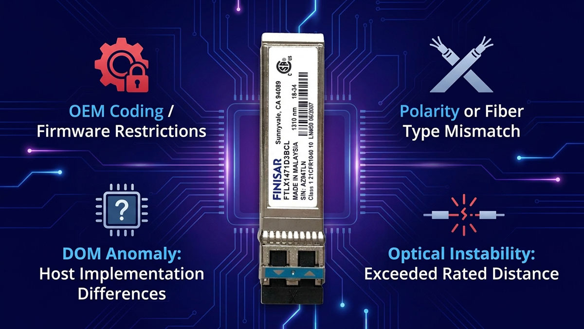
Most FTLX1471D3BCL compatibility problems are caused by a mismatch somewhere in the complete link rather than by the SFP+ form factor itself. The most important areas to investigate are host recognition, fiber and wavelength compatibility, connector condition, optical power, and host-side electrical behavior. FTLX1471D3BCL is a 10Gb/s, 1310nm, 10km Single Mode Fiber module with a limiting receiver and SFF-8472 digital diagnostics, so troubleshooting should follow these characteristics.
Module Not Recognized by the Host
When FTLX1471D3BCL is not recognized, the first checks should focus on the host's SFP+ support, transceiver identification, and platform-specific restrictions. The module's EEPROM and serial-interface functions are part of the host-module interaction, so a physical connection does not necessarily mean that the host will accept or report the module correctly.
Check the following items in sequence:
- Confirm that the port is an SFP+ 10G interface.
- Verify that the host supports the intended 10G optical application.
- Check whether the platform restricts transceivers according to vendor identification or EEPROM information.
- Inspect the module seating and cage connection.
- Check the host's transceiver inventory or interface diagnostics.
- Verify that the module receives the required 3.3V supply.
- Check firmware or platform documentation for supported transceiver revisions.
- If DOM information is unavailable, confirm whether the host supports the module's SFF-8472 diagnostic interface.
FTLX1471D3BCL provides a 2-wire serial interface for digital diagnostics, while its host interface also includes module-absent, transmitter-fault, transmitter-disable, and receiver-loss-of-signal functions. These signals can provide useful clues when the host reports an abnormal module state.
Link Remains Down
If the module is detected but the optical link remains down, the most likely causes are an optical mismatch, incorrect fiber connection, insufficient received power, or an issue at the remote endpoint. FTLX1471D3BCL is designed for 1310nm Single Mode Fiber operation, so both ends of the link must provide a compatible optical path.
A systematic check should include:
- Confirm that both endpoints support the intended 10GBASE-LR/LW application.
- Verify that the installed fiber is Single Mode Fiber.
- Confirm that the optical path is appropriate for 1310nm operation.
- Check that the total link distance does not exceed the specified 10km reach.
- Inspect duplex LC connectors and fiber polarity.
- Confirm that Tx at one endpoint connects to Rx at the other endpoint.
- Check whether the remote optic has compatible wavelength, reach, and application specifications.
- Inspect the fiber and connectors for contamination or physical damage.
The module's receiver includes a loss-of-signal indication, which can help distinguish an optical signal problem from other host-side issues. The datasheet specifies that a logic high on RX_LOS indicates loss of signal, while a logic low represents normal operation.
Unexpected DOM Readings
Unexpected DOM readings do not necessarily mean that the optical module is defective. They may result from host interpretation, diagnostic implementation, or actual changes in module temperature, laser bias, or optical power. FTLX1471D3BCL provides digital diagnostics through the SFF-8472 2-wire serial interface.
When DOM values appear abnormal, check:
- Module temperature.
- Laser bias current.
- Transmitted optical power.
- Received optical power.
- Host-reported alarm and warning states.
- Whether the host correctly supports SFF-8472 diagnostics.
- Whether the reported values change consistently with link conditions.
Compare the readings with the module's specified operating conditions rather than judging a single DOM value in isolation. For example, a low received optical power reading should prompt an inspection of the fiber path and remote transmitter before the module itself is considered the source of the problem.
Optical Errors or Unstable Links
Optical errors or repeated link transitions usually indicate that the complete optical budget or physical connection needs further investigation. FTLX1471D3BCL has a specified 10km reach, but actual link performance also depends on fiber attenuation, connector loss, splice loss, and the optical characteristics of the remote transceiver.
The troubleshooting process should cover:
- Check received optical power: Determine whether the receiver is obtaining a sufficient optical signal.
- Inspect the fiber path: Look for excessive attenuation, damaged patch cords, or poor splices.
- Clean the LC connectors: Contamination can introduce significant insertion loss.
- Check link polarity: Verify correct Tx/Rx orientation across the complete duplex path.
- Compare both endpoints: Make sure the remote optic is compatible with the FTLX1471D3BCL optical architecture.
- Review interface counters: Look for increasing errors, loss-of-signal events, or repeated link resets.
- Check host-side PHY behavior: The FTLX1471D3BCL is a limiting module, and Finisar specifically notes that host EDC PHY implementations should use the PHY manufacturer's recommended settings when operating with a limiting-receiver SFP+ module.
A stable link should ultimately be validated under normal traffic rather than only by confirming that the interface changes to an "up" state. If optical levels remain within the expected range and the physical path is clean, persistent errors should then be investigated at the host electrical interface, firmware, configuration, or remote endpoint.
🚩 How to Read the FTLX1471D3BCL Datasheet for Compatibility
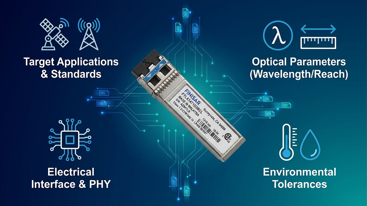
The FTLX1471D3BCL datasheet should be read as a compatibility checklist rather than simply a specification sheet. Start with the application and standards, then verify the optical parameters, host-side electrical requirements, and finally the environmental and diagnostic characteristics. This approach helps determine whether FTLX1471D3BCL is suitable for a specific 10G link before installation. The datasheet identifies support for 10GBASE-LR/LW, 1200-SM-LL-L 10G Fibre Channel, SFF-8431, SFF-8432, and SFF-8472.
Start With Application and Standards
The first section to check is the application and standards, because these establish whether the module is intended for the network technology being deployed. FTLX1471D3BCL is specified for 10GBASE-LR/LW 10G Ethernet and 1200-SM-LL-L 10G Fibre Channel.
When reading this part of the datasheet, verify:
- 10G Ethernet: Confirm that the target interface supports 10GBASE-LR/LW.
- Fibre Channel: For storage networks, confirm support for the specified 1200-SM-LL-L 10G Fibre Channel application.
- IEEE standard: Check the host documentation against IEEE 802.3ae where 10G Ethernet is used.
- SFP+ interface standards: Verify SFF-8431 and SFF-8432 compatibility.
- Diagnostic interface: Check whether the host supports the SFF-8472-based diagnostic functions.
This first check eliminates many potential mismatches before detailed optical analysis begins. A host that does not support the intended application should not be considered compatible simply because it has an SFP+ port.
Check Optical Parameters Next
Once the application is confirmed, the optical section becomes the next priority because it determines whether FTLX1471D3BCL matches the physical fiber link. The module is designed for 10Gb/s transmission up to 10km over Single Mode Fiber and uses an uncooled 1310nm DFB laser with a duplex LC connector.
Focus on these optical parameters:
- Wavelength: 1310nm-class operation.
- Fiber type: Single Mode Fiber.
- Reach: Maximum specified link length of 10km.
- Transmitter: Uncooled 1310nm DFB laser.
- Receiver: Limiting receiver.
- Connector: Duplex LC.
- Optical power: Compare transmitter and receiver specifications with the actual link budget.
- Receiver sensitivity: Check whether the expected received optical power remains within the specified operating range.
The key point is to evaluate these parameters as a complete optical system. For example, matching 1310nm alone does not establish compatibility if the installed fiber is unsuitable, the distance exceeds the specified reach, or the optical loss is too high.
Review Host-Side Electrical Requirements
After the optical path is confirmed, check the electrical specifications that determine how FTLX1471D3BCL interacts with the host device. The datasheet specifies a single 3.3V power supply, an SFP+ electrical interface, and a limiting receiver. It also notes that host-board designers using an EDC PHY should follow the PHY manufacturer's recommended settings when interoperating with a limiting-receiver SFP+ module.
Important host-side checks include:
- Power supply: Confirm that the host provides the required 3.3V supply.
- Electrical interface: Verify SFF-8431-related electrical compatibility.
- SFP+ footprint: Confirm the physical and electrical interface of the host cage.
- Receiver architecture: Consider the limiting-receiver implementation.
- PHY configuration: Check EDC PHY recommendations where applicable.
- Hot-plug support: Verify that the host platform supports the intended SFP+ installation method.
This section is particularly important when compatibility is being evaluated at the hardware-design level. Optical specifications may be correct while host-side PHY behavior still prevents reliable interoperability.
Finish With Environmental and Monitoring Requirements
The final stage is to review the environmental and diagnostic specifications. These parameters may not determine basic optical interoperability, but they can determine whether the module is appropriate for the intended operating environment and whether its diagnostic functions can be used effectively.
The relevant checks include:
- Operating temperature: Confirm that the deployment remains within the specified commercial range of -5°C to 70°C.
- Power dissipation: Check whether the host can accommodate the module's specified power consumption of less than 1W.
- RoHS compliance: Verify environmental compliance requirements where applicable.
- Digital diagnostics: Confirm that the host can access the module's diagnostic functions.
- Monitoring parameters: Check whether temperature, laser bias, Tx optical power, and Rx optical power can be monitored.
- Storage conditions: Consider the specified storage temperature when modules are kept outside active equipment.
FTLX1471D3BCL provides digital diagnostic functions through a 2-wire serial interface specified by SFF-8472, making DOM information useful for post-installation verification and troubleshooting.
🚩 Conclusion
Finisar FTLX1471D3BCL is a 10Gb/s SFP+ optical transceiver designed for 1310nm Single Mode Fiber transmission over distances of up to 10km. Evaluating the FTLX1471D3BCL datasheet and FTLX1471D3BCL compatibility together is essential because successful deployment depends on the complete relationship between the module, host equipment, fiber infrastructure, and remote endpoint.
The key points to remember are:
- Optical: 1310nm, Single Mode Fiber, up to 10km, duplex LC.
- Network: 10GBASE-LR/LW Ethernet and specified 10G Fibre Channel applications.
- Host: SFP+ interface, compatible electrical requirements, and applicable platform support.
- Diagnostics: SFF-8472-based digital diagnostic monitoring.
- Deployment: Verify fiber type, optical loss, connector polarity, host recognition, and link stability before operation.
For network upgrades or replacement planning, the same technical checklist can also be applied when evaluating compatible 10G SFP+ alternatives. LINK-PP Official Store offers a broad range of optical transceiver modules, including 10G SFP+ solutions, providing another resource for comparing module specifications and network connectivity options.
Ultimately, treating the datasheet as the starting point for compatibility verification helps reduce deployment errors and makes it easier to select a 10G optical solution that matches the actual requirements of the network.