
As data centers scale up to meet skyrocketing bandwidth demands, network engineers face a frustrating dilemma: how to bridge the gap between high-speed 40G core switches and existing 10G infrastructure without breaking the bank or sacrificing signal integrity? While short-range multi-mode options are a common go-to, they often fall short when your network needs to stretch across larger data center footprints.
This is exactly where the QSFP 4x10G LR S transceiver comes into play as a game-changing alternative. By leveraging parallel single-mode technology, the QSFP 4x10G LR S allows you to split a single 40G port into four pristine 10G channels over much longer distances. But how does it truly stack up against the QSFP 40GBASE-SR4 optics transceiver in terms of cabling infrastructure, performance, and cost? Let’s dive in and find out.
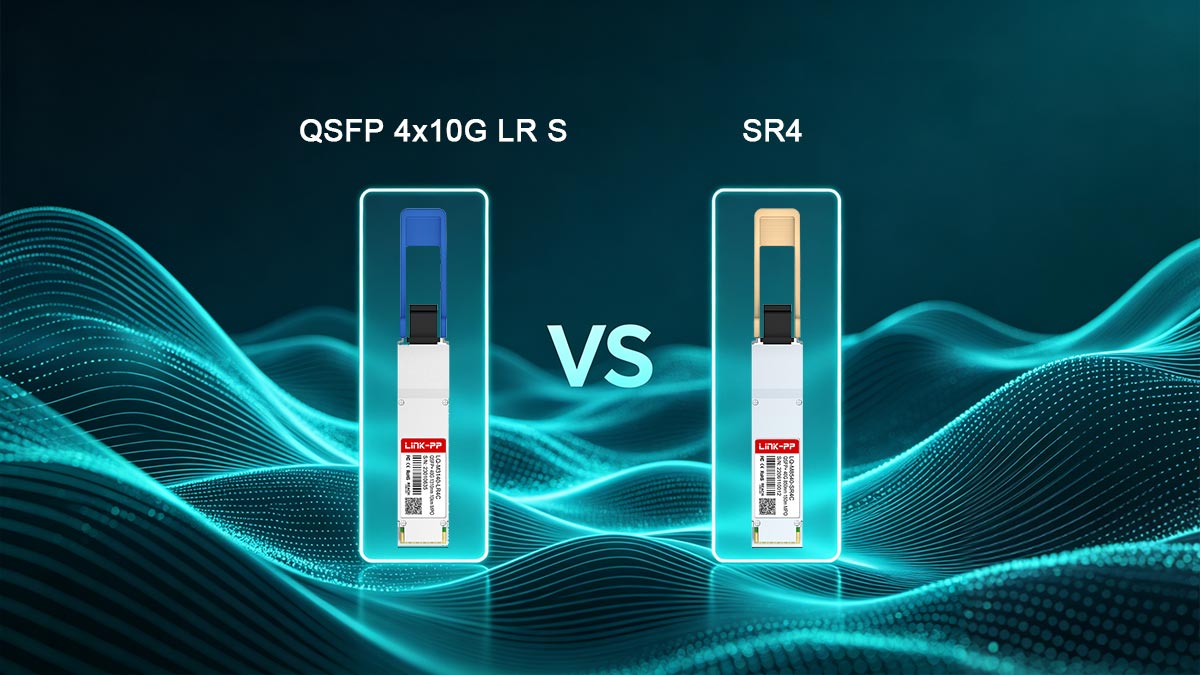
☁️ Understanding the Basics of QSFP 4x10G LR S vs. SR4
Navigating the world of high-speed data center transceivers requires a solid grasp of how different optical standards operate. Choosing between single-mode and multi-mode solutions directly impacts network reach, infrastructure costs, and long-term scalability. Laying the groundwork for these two distinct technologies makes it easier to evaluate which option best aligns with specific architecture goals.
What Is a QSFP 4x10G LR S Transceiver
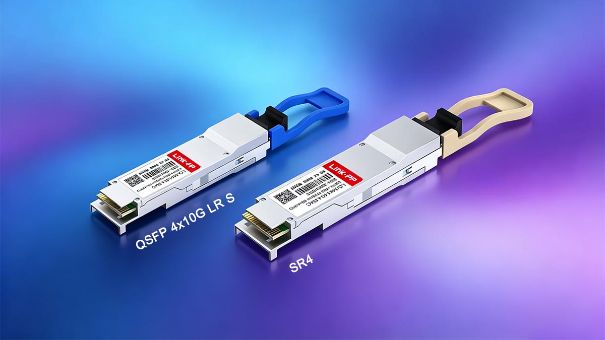
The QSFP 4x10G LR S is a hot-pluggable optical transceiver designed for high-density, mid-to-long-reach 40-Gigabit Ethernet applications. It utilizes Parallel Single-Mode (PSM4) technology to transmit data over four independent lanes, with each lane operating at 10Gbps.
By operating over a single-mode fiber infrastructure using a 1310nm wavelength, this optical module can achieve transmission distances of up to 10km. It typically uses an MPO/MTP connector interface, making it highly efficient for direct high-speed links or 40G-to-10G breakout configurations.
What Is a QSFP 4x10G SR4 Transceiver
The QSFP 4x10G SR4 is a short-range optical transceiver widely deployed for localized, high-speed data center connections. Like its single-mode counterpart, it splits a 40G signal into four parallel 10G channels to maximize port density and throughput.
However, the SR4 variant operates over multi-mode fiber cabling (such as OM3 or OM4) at a short wavelength of 850nm. Because it relies on lower-cost VCSEL lasers, its reach is physically limited to around 100m to 150m, making it ideal for intra-rack and inter-rack deployments.
The Core Differences Between Single-Mode and Multi-Mode Fiber
To truly understand how these transceivers perform, one must look at the underlying glass infrastructure that carries the light signals. Single-mode and multi-mode fibers are engineered differently, resulting in vastly different performance boundaries regarding distance and signal degradation.
The following breakdown highlights the structural and operational differences between these two primary fiber types:
| Feature |
Single-Mode Fiber (SMF) |
Multi-Mode Fiber (MMF) |
| Core Diameter |
Tiny (typically around 9μm) |
Much larger (typically 50μm or 62.5μm) |
| Light Propagation |
Allows only a single mode/path of light |
Allows multiple paths of light to travel simultaneously |
| Modal Dispersion |
Virtually zero, allowing for pristine signal integrity |
Higher dispersion, which limits the transmission distance |
| Optimal Distance |
Ideal for long distances (up to 10km or more) |
Restricted to short distances (up to 100m - 400m) |
Why Parallel Optical Technology Matters for 40G Networks
Parallel optical technology completely redefines how data centers scale by moving away from traditional single-lane serial transmission. Instead of multiplexing multiple frequencies onto one fiber strand, parallel optics stream data simultaneously across multiple fibers using a single MPO/MTP connector.
This parallel architecture is what allows both the QSFP 4x10G LR S and SR4 modules to easily split a 40G port into four distinct 10G connections. Ultimately, this approach simplifies the migration from 10G to 40G networks while offering unparalleled flexibility for leaf-spine data center designs.
☁️ Optical Specifications Comparison: QSFP 4x10G LR S vs. SR4
Evaluating the hardware specifications of these two 40G QSFP+ transceivers reveals the precise technical boundaries that dictate their performance. These metrics directly influence how light travels through the glass, defining the physical limits of a network layout. Understanding these core numbers ensures that hardware choices perfectly match the architectural goals of the data center.
Wavelength and Laser Source Discrepancies
The QSFP 4x10G LR S utilizes a 1310nm wavelength powered by highly precise Distributed Feedback (DFB) lasers. This specific wavelength experiences very low attenuation in glass, making it highly effective for driving optical signals over expansive distances. The focused light allows the signal to travel cleanly without spreading out prematurely.
In contrast, the SR4 transceiver operates at a much shorter 850nm wavelength, using Vertical-Cavity Surface-Emitting Lasers (VCSELs). These lasers are highly cost-effective and energy-efficient, making them perfect for short bursts of communication. However, the 850nm wavelength naturally scatters faster in fiber, which restricts its use to localized connections.
Cable Distance and Reach Capabilities
When it comes to spanning physical space, the QSFP 4x10G LR S offers massive reach advantages. It can seamlessly transmit data across links reaching up to 10km without needing intermediate signal amplification. This expansive reach makes it the go-to solution for connecting entirely separate facilities or massive hyperscale data halls.
The SR4 transceiver, meanwhile, is purpose-built for ultra-short distances within a tight perimeter. It generally tops out at 100m on OM3 cables and stretches to roughly 150m on premium OM4 multi-mode fiber. While this range is perfect for linking switches within the same rack row, it cannot handle long campus spans.
Fiber Core Diameters and Compatibility
The optical core of the fiber used alongside the QSFP 4x10G LR S measures a tiny 9μm in diameter. This ultra-narrow channel forces the light to travel in a straight, concentrated path, eliminating any chance of the signal bouncing around. However, this microscopic size demands incredibly precise alignment when mating connectors together.
On the flip side, the SR4 variant pairs with a much wider 50μm multi-mode fiber core. This larger opening makes it far easier to inject light from affordable VCSEL sources without needing extreme alignment tolerances. The trade-off is that the wider core permits multiple light paths, causing data paths to overlap over long distances.
Optical Power Budget and Insertion Loss
The QSFP 4x10G LR S features a more robust optical power budget to combat the signal loss that accumulates over kilometers of fiber. Its powerful transmitters push a stronger signal through the line, ensuring that the light remains readable even after passing through multiple patches. This extra budget protects the network against unexpected dips in signal quality.
The SR4 module operates with a much tighter power budget because it only has to survive short-distance cable runs. Insertion loss from dirty or misaligned connectors can quickly deplete this smaller budget, leading to dropped packets. Consequently, maintaining pristine cleanliness at every patch panel is vital for keeping SR4 links stable.
☁️ Fiber Cabling Infrastructure for QSFP 4x10G LR S vs. SR4
Selecting the appropriate physical cabling layer is essential for unlocking the full potential of high-density optical hardware. The choice between single-mode and multi-mode pathways directly dictates how backbones are routed and patched across the data center floor. Aligning the physical cable plants with the correct transceiver type ensures maximum data throughput and seamless network stability.
MTP/MPO Connector Requirements for Both Transceivers
Both of these 40G modules rely on multi-fiber push-on connectors to manage their parallel optical channels over a compact footprint. However, the precise internal alignment and polishing requirements differ significantly based on the fiber type used. The QSFP 4x10G LR S benefits from more stringent connector standards to maintain pristine laser transmission.
The following points outline the specific connector criteria for these modules:
- Uses 12-fiber MPO or MTP connector interfaces.
- Utilizes 8 active fiber strands out of 12 to transmit and receive data.
- Requires Angle Physical Contact (APC) polishing for single-mode to stop reflections.
- Uses Ultra Physical Contact (UPC) flat-faced polishing for multi-mode SR4 optics.
- Benefits from the high precision of single-mode connectors to minimize signal loss.
Deploying Parallel Single-Mode (PSM4) Ribbon Cables
Deploying parallel single-mode ribbon cabling alongside the QSFP 4x10G LR S offers a massive leap forward in long-range network architecture. This infrastructure type allows data centers to combine the extreme distance capabilities of single-mode glass with the density of parallel optics. It provides a future-proof foundation that easily adapts to next-generation network upgrades.
Key advantages and traits of deploying this ribbon cable infrastructure include:
- Supports data transmission up to 10km over yellow single-mode jacketed fiber.
- Allows seamless, direct connection layouts without needing complex optical conversion hardware.
- Offers much lower cable attenuation compared to any multi-mode layout.
- Provides a highly reliable pathway that is immune to modal dispersion issues.
- Creates a highly scalable foundation ready for future 100G and 400G migrations.
Deploying OM3/OM4 Multi-Mode Fiber Layouts
OM3 and OM4 multi-mode fiber layouts are traditional choices tailored exclusively for localized, short-distance data center clusters. These networks utilize aqua or violet-colored cable jackets that are highly visible and easy to trace within a routing system. While they are easy to deploy initially, they face rigid physical limitations when data center environments grow.
The core characteristics of these multi-mode deployments involve:
- Limits maximum reach to 100m on OM3 and 150m on OM4.
- Uses larger fiber cores that make basic field termination highly forgiving.
- Suffers from rapid signal degradation if cables are bent beyond tight limits.
- Requires frequent upgrades as network speeds outgrow old multi-mode standards.
Cable Management and Density Considerations in Data Centers
High-density data centers require smart cable management to prevent messy overhead trays and blocked airflow inside equipment racks. The QSFP 4x10G LR S drastically reduces physical bulk because single-mode ribbon cables are thinner than high-bandwidth multi-mode bundles. This allows network engineers to maximize space efficiency while improving overall cooling performance.
Optimizing data center density with these cabling solutions highlights several key factors:
- Saves critical overhead tray space by using thinner single-mode fiber jackets.
- Lowers the total weight load on cable ladders and under-floor pathways.
- Improves cooling airflow inside high-density server racks due to less cable bulk.
- Reduces total patch panel clutter when routing long-distance campus links.
- Enhances overall layout organization for easier tracking and faster troubleshooting.
☁️ 40G to 10G Breakout Performance: QSFP 4x10G LR S vs. SR4
Maximizing port density and improving hardware utilization often requires splitting a high-bandwidth interface into multiple lower-speed connections. Executing a 40G to 10G breakout strategy allows legacy equipment to communicate seamlessly with next-generation core switches. Comparing how single-mode and multi-mode transceivers handle this channel splitting reveals critical differences in deployment flexibility and signal behavior over distance.
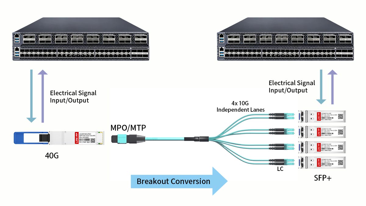
How the 4x10G Channel Splitting Works
Both the QSFP 4x10G LR S and SR4 optics achieve channel splitting by utilizing internal architecture that maps independent data streams to specific fiber strands. Instead of combining everything into a single composite beam, the transceiver treats its interface as four separate, isolated ports operating simultaneously. The host switch configuration simply needs to be set to breakout mode to recognize the single 40G physical slot as four distinct 10G logical links.
This hardware-level splitting happens instantly inside the module without causing any processing delays or software overhead. Because the data paths are physically isolated on separate glass strands, a failure or disruption on one 10G channel will not affect the traffic flowing through the remaining three lanes. This makes parallel channel splitting an incredibly robust method for scaling network density without sacrificing overall uptime.
MPO-to-LC Breakout Cable Configurations
To physically distribute the split signals to individual servers or downstream switches, an MPO-to-LC breakout cable is required. For the QSFP 4x10G LR S, this means using a single-mode breakout cable that features an MPO connector on one end and eight separate LC connectors on the other. This configuration directly routes the four independent transmit and receive fiber pairs to standard 10G SFP+ ports across the data center.
When using the SR4 module, a matching multi-mode MPO-to-LC breakout cable is deployed instead. The mechanical layout remains identical, but the internal glass core matches the wider multi-mode standard. For both types, careful labeling of the individual LC legs is absolutely critical to ensure that transmit lines match up correctly with their corresponding receive endpoints.
Parallel Single-Mode Performance in Leaf-Spine Architectures
In modern leaf-spine data center designs, the QSFP 4x10G LR S offers a massive advantage by breaking the physical distance barriers of standard short-range optics. Spine switches located in a central telecom room can use breakout cables to connect directly to leaf switches distributed across entirely separate rows or floors. This parallel single-mode approach eliminates the need for expensive intermediate aggregation switches, drastically simplifying the network fabric.
Traditional SR4 breakouts are strictly bound to localized clusters due to their short-distance limitations. If a leaf switch sits more than 150m away from the spine, multi-mode breakouts simply cannot be used. The QSFP 4x10G LR S fills this gap perfectly, allowing data centers to maintain a flat, high-speed leaf-spine topology over kilometers of campus infrastructure.
Latency and Signal Integrity at 10G Speeds
At 10G speeds, maintaining pristine signal integrity is vital for low-latency environments like high-frequency trading or real-time cloud computing. The QSFP 4x10G LR S excels here because its laser signals travel through single-mode fiber with zero modal dispersion. This lack of distortion ensures that data packets arrive intact and perfectly timed, keeping jitter to an absolute minimum over long distances.
The SR4 module delivers excellent low-latency performance as well, but only within its ultra-short physical operating range. As the multi-mode cable approaches its maximum distance limit, modal dispersion begins to stretch the light pulses, which can trigger bit errors. These errors force packet retransmissions, creating unpredictable latency spikes that can degrade overall application performance.
☁️ Cost Analysis and ROI of QSFP 4x10G LR S vs. SR4
Balancing upfront capital expenditures against long-term operational savings is a critical step when designing a data center network. While one optical solution might seem cheaper on paper, hidden infrastructure and maintenance costs can drastically shift the financial outlook over time. A thorough economic evaluation helps ensure that your choice maximizes return on investment without overextending your budget.
Transceiver Initial Purchase Price Comparison
From a pure hardware standpoint, the initial purchase price of a QSFP 4x10G LR S transceiver is typically higher than that of an SR4 module. This price difference stems from the complex Distributed Feedback (DFB) lasers required to shoot precise light signals over single-mode glass. In contrast, the SR4 optics utilize mass-produced, lower-cost VCSEL lasers, making them highly economical for a tight upfront hardware budget.
Structured Cabling Expenses (SMF vs. MMF Fiber Costs)
While single-mode transceivers cost more, the actual structured cabling glass for the QSFP 4x10G LR S is significantly less expensive per meter than multi-mode OM3 or OM4 fiber. Multi-mode glass requires complex internal manufacturing to handle multiple light paths, which drives up its bulk price. Consequently, as physical cable distances and network footprints expand across the facility, the savings on single-mode glass can easily offset the higher transceiver costs.
Long-Term Power Consumption and Operational Costs
Operating costs require a careful evaluation of power allocation and heat dissipation within high-density server racks. The SR4 module is exceptionally energy-efficient for short runs, drawing less than 1.5W of power per unit. Meanwhile, the long-reach QSFP 4x10G LR S draws less than 3.5W due to its more powerful lasers, requiring network engineers to factor in slightly higher power overhead and cooling requirements for extensive single-mode deployments.
Total Cost of Ownership for Large-Scale Deployments
When calculating the Total Cost of Ownership (TCO) for large-scale data centers, the QSFP 4x10G LR S frequently delivers a superior return on investment despite its 3.5W power draw. It eliminates the need to buy intermediate aggregation switches or repeaters, allowing networks to maintain a flat, simplified architecture over long distances. Furthermore, because single-mode fiber infrastructure easily supports future migrations to 100G and 400G, it saves organizations from expensive, disruptive recabling overhauls down the road.
☁️ Best Use Cases and Applications for QSFP 4x10G LR S vs. SR4
Deploying the right optical hardware depends heavily on the specific architecture, scale, and performance needs of the networking environment. Each transceiver is optimized for distinct operational zones, from tightly packed server rows to more expansive across-campus backbones. Matching the hardware to its most effective application helps guarantee optimal network performance while keeping infrastructure costs fully aligned.
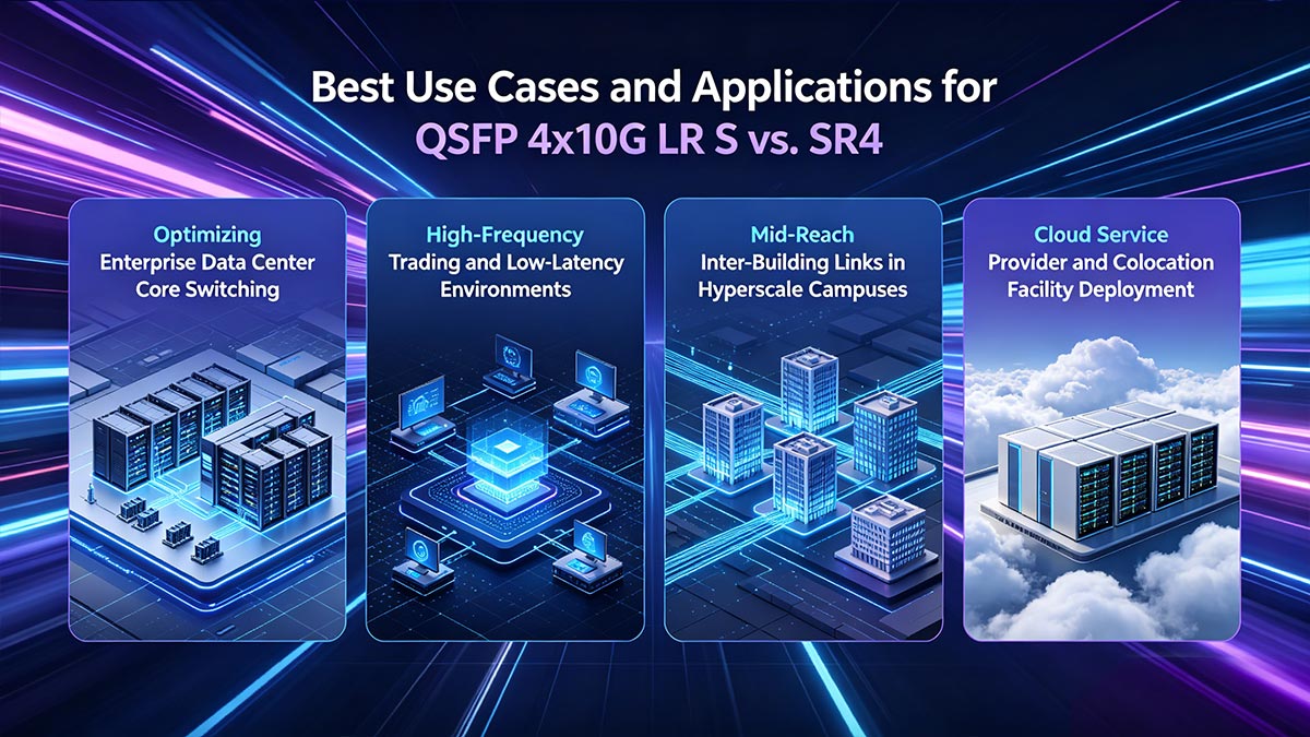
Optimizing Enterprise Data Center Core Switching
The QSFP 4x10G LR S is well-suited for central core switches that need to consolidate high-density data across expansive corporate campuses. Its long-reach capabilities allow it to reliably connect main distribution frames to remote network segments located kilometers away.
On the other hand, the SR4 module remains a highly practical and common choice for localized top-of-rack or end-of-row switch aggregation. It excels at linking standard access layers inside single, enclosed server rooms where cable spans typically stay well under 150 meters.
High-Frequency Trading (HFT) and Low-Latency Environments
In high-frequency trading networks, the QSFP 4x10G LR S can provide excellent signal stability for mid-range runs between financial server floors. Because single-mode glass minimizes modal dispersion, it helps ensure light pulses travel with high precision and minimal timing variations over longer distances.
The SR4 transceiver also offers ultra-low latency, making it a staple for supercomputing clusters, particularly over localized distances. However, if the trading layout expands significantly across a large facility, engineers must carefully monitor multi-mode fiber to prevent signal jitter from affecting transaction consistency.
Mid-Reach Inter-Building Links in Hyperscale Campuses
Hyperscale campuses routinely require connections that cross physical limits where traditional multi-mode cables may become impractical or unreliable. The QSFP 4x10G LR S acts as an ideal bridge here, enabling 40G parallel links to safely cross wide campus roadways and outdoor pathways up to several kilometers.
Deploying SR4 optics in this scenario is generally not recommended due to its standard 150-meter distance ceiling. Attempting to force standard multi-mode gear into extended inter-building backbones often results in severe signal dropouts and unreadable data streams.
Cloud Service Provider and Colocation Facility Deployment
Cloud service providers frequently utilize the QSFP 4x10G LR S to establish flexible, high-density breakout connections across multi-tenant colocation facilities. It allows operators to hand off precise 10G customer channels over a unified single-mode infrastructure that can reach any corner of a massive building.
Colocation cages that only require standard local server-to-switch mapping often rely on the cost-effective SR4 module instead. This allows facility managers to optimize their localized hardware budget while reserving single-mode setups for primary exterior pathways or extended cross-connects.
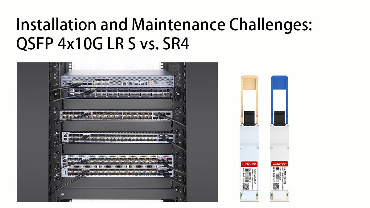
☁️ Installation and Maintenance Challenges: QSFP 4x10G LR S vs. SR4
Deploying high-speed parallel optics introduces distinct physical handling and troubleshooting requirements for data center technicians. Properly managing these components ensures long-term link reliability and prevents unexpected network downtime. Addressing these daily operational challenges head-on keeps both single-mode and multi-mode networks running at peak efficiency.
Handling and Cleaning Parallel Single-Mode MPO Connectors
The tiny 9-micrometer core of single-mode fiber makes the QSFP 4x10G LR S highly sensitive to microscopic dust particles. While the larger 50-micrometer core of SR4 multi-mode fiber is slightly more forgiving, a single speck of dirt on either parallel connector face can block multiple channels simultaneously.
Adhering to strict cleaning protocols is vital to protect both types of data streams:
- Inspect every MPO connector face with a fiber microscope before plugging it in.
- Use specialized MPO click-cleaners designed specifically for parallel arrays.
- Avoid touching the connector tips with bare fingers to prevent oil transfer.
- Clean both the cable connector and the transceiver optical port interface.
- Re-cap all unused ports immediately to block airborne contaminants.
Troubleshooting Signal Attenuation in High-Distance Links
Over extended distances, the QSFP 4x10G LR S can suffer from signal attenuation caused by macro-bends or dirty patch panels. In contrast, SR4 optics rarely face long-distance attenuation but are highly susceptible to modal dispersion if cable runs exceed 150 meters.
Technicians should utilize these specific troubleshooting steps to locate signal drops:
- Use an Optical Time-Domain Reflectometer (OTDR) to map the entire fiber run.
- Check the switch software for Digital Optical Monitoring (DOM) real-time power levels.
- Inspect patch panels for tight cable bends that cause light leakage.
- Verify that single-mode APC angled connectors are not mixed with flat UPC connectors.
- Clean and re-test any connection points showing high insertion loss.
Heat Dissipation and Thermal Management in High-Density Racks
Thermal management is a critical factor when grouping multiple high-power transceivers into a single network switch. Because the QSFP 4x10G LR S generates more heat (typically <3.5W) than short-range SR4 modules (<1.5W), packed single-mode environments require careful environmental monitoring.
Managing rack temperatures effectively involves implementing the following data center practices:
- Maintain a steady, functional hot/cold aisle containment system.
- Use blanking panels in empty rack slots to keep airflow directional.
- Monitor internal switch temperature sensors regularly via network management software.
- Space out higher-power single-mode transceivers across different line cards if possible.
- Ensure data center cooling systems can handle the cumulative thermal load.
Field Testing Guidelines for 4x10G Parallel Channels
Testing a parallel optical link requires verifying all four independent 10G channels rather than treating the cable as a single pathway. Standard single-fiber testers cannot interface with either QSFP 4x10G LR S or SR4 gear without specific adaptation hardware.
Engineers should follow these testing guidelines to certify parallel channels properly:
- Use dedicated MPO/MTP power meters to test all active strands simultaneously.
- Deploy specialized breakout test cables to isolate individual 10G channels.
- Run Bit Error Rate Testing (BERT) on each lane to check packet integrity.
- Document reference baseline loss measurements for every newly installed link.
- Cross-reference field test results with the hardware manufacturer's power budget limits.
☁️ Choosing the Right Parallel Optics: QSFP 4x10G LR S vs. SR4
Selecting between these two parallel optical solutions ultimately comes down to matching your data center's physical layout with your long-term scaling strategy. If your priority is a budget-friendly, short-range setup confined to a few localized racks, the 40G QSFP+ SR4 module remains an excellent, energy-efficient choice. However, when your architecture demands reliable performance across longer spans or requires a future-proof single-mode backbone, investing in the QSFP 4x10G LR S is the more strategic path.
Ready to optimize your network infrastructure with reliable, high-performance optical gear? Explore a comprehensive selection of premium, fully compatible transceivers by visiting the LINK-PP Official Store, where you can find the perfect hardware to power your network. Our team is always available to help you choose the ideal parallel optics transceiver tailored to your specific infrastructure needs.


