
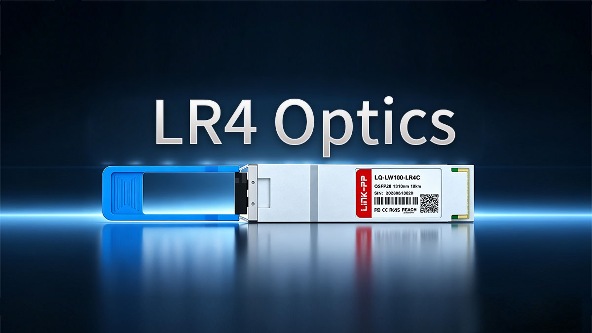
As modern data centers expand across sprawling campus environments and metropolitan areas, maintaining fast, reliable connections over long distances has become a top priority. LR4 optics serve as a critical solution to this challenge, enabling seamless high-bandwidth data transmission over distances up to 10km. By leveraging single-mode fiber, these specialized optical transceivers bridge the physical gap between distributed facilities without sacrificing speed or signal quality.
In high-density network architectures, achieving this 10km reach is the ultimate "sweet spot" for connecting core-to-core and spine-to-spine switches. Understanding how to deploy, optimize, and maintain LR4 optics is essential for minimizing latency and keeping infrastructure costs under control. This article will dive into the technical characteristics, deployment best practices, and troubleshooting steps needed to maximize your long-haul network performance.
📃 The Strategic Role of LR4 Optics in 10km Data Center Interconnects (DCI)
Data Center Interconnect (DCI) strategies rely on robust hardware to ensure separate facilities function smoothly as a single, unified network. As corporate applications and cloud services expand, selecting the right optical transceivers dictates how effectively data moves across wide geographical areas. Understanding the strategic value of long-reach solutions helps network engineers build resilient, future-proof pathways between critical facilities.
Bridging the Distance Gap Between Metro Data Center Sites
Modern enterprises frequently distribute their physical infrastructure across a metropolitan region to guarantee high availability and disaster recovery. Connecting these separate sites requires optical equipment that can handle significant distances without requiring expensive intermediate signal amplifiers.
LR4 optics offer the perfect remedy by easily covering up to 10km of single-mode fiber infrastructure. This native long-distance capability allows distinct municipal facilities to sync databases and share computing workloads seamlessly, behaving as if they were located within the exact same room.
Meeting High-Bandwidth Demands Without Signal Degradation
As massive artificial intelligence workloads and cloud data streaming multiply, network backbones must carry unprecedented volumes of data simultaneously. Traditional short-range optics fail quickly at these scales, as their signals rapidly lose clarity when pushed beyond a few hundred meters.
LR4 optics transceivers solve this by transmitting high-speed data over four distinct, tightly packed light wavelengths over a single fiber pair. This advanced design ensures massive bandwidth capacity while keeping the light signal incredibly clean, sharp, and error-free over long hauls.
Why 10km Reach is the Sweet Spot for Campus-Scale Backbones
In large enterprise and hyperscale environments, building networks on a massive physical campus creates unique distance challenges between buildings. Shorter-range standards like SR4 or CWDM4 often fall short when fiber cables must route through winding underground conduits.
The 10km rating of LR4 optics provides a comfortable buffer that easily absorbs the unexpected physical length added by complex facility routing. This makes it the ideal standard for campus backbones, offering maximum flexibility without the extreme costs associated with ultra-long-haul telecom optics.
📃 Key Technical Characteristics of 10km LR4 Optics Explained
Evaluating the internal mechanics of long-reach optical transceivers reveals why they perform so reliably over extended distances. Unlike basic short-range modules, these components use advanced laser configurations and strict power management to keep data moving at peak efficiency. Examining these core technical design elements highlights the engineering that makes 10km transmission stable and predictable.
Leveraging LAN-WDM Wavelengths for Zero-Latency Transmission
LR4 optics transceivers rely on LAN-WDM wavelength grids to pack multiple channels into a single optical fiber without causing interference. These wavelengths are tightly spaced in the 1310nm window, where optical fiber naturally experiences the least amount of signal stretching and distortion. This precise frequency alignment enables high-speed data streams to travel side-by-side with virtually zero processing delay.
The following core attributes define how this wavelength technology operates:
- Four channels: It splits data across four distinct light frequencies.
- Tight spacing: Wavelengths sit incredibly close together to maximize efficiency.
- Low dispersion: It targets the fiber spectrum with the lowest natural distortion.
- No internal buffering: Light passes through instantly without adding electronic latency.
Understanding the 10km Optical Power Budget and Receiver Sensitivity
The success of a 10km optical link depends heavily on maintaining an adequate balance between transmitted light energy and receiver detection capabilities. The optical power budget represents the total amount of signal loss, measured in decibels, that the light can endure along its path. High-quality LR4 optics modules feature incredibly sharp receiver sensitivity to catch and read faint, diminished light signals at the far end of the cable.
Key factors that govern this optical power balancing act include:
- Launch power: The initial strength of the light leaving the transmitter laser.
- Receiver sensitivity: The minimum light level required to read data accurately.
- Link loss margin: The allowable power drop caused by fiber distance and connection points.
- Bit error prevention: Strong power margins keep data clean and prevent dropped packets.
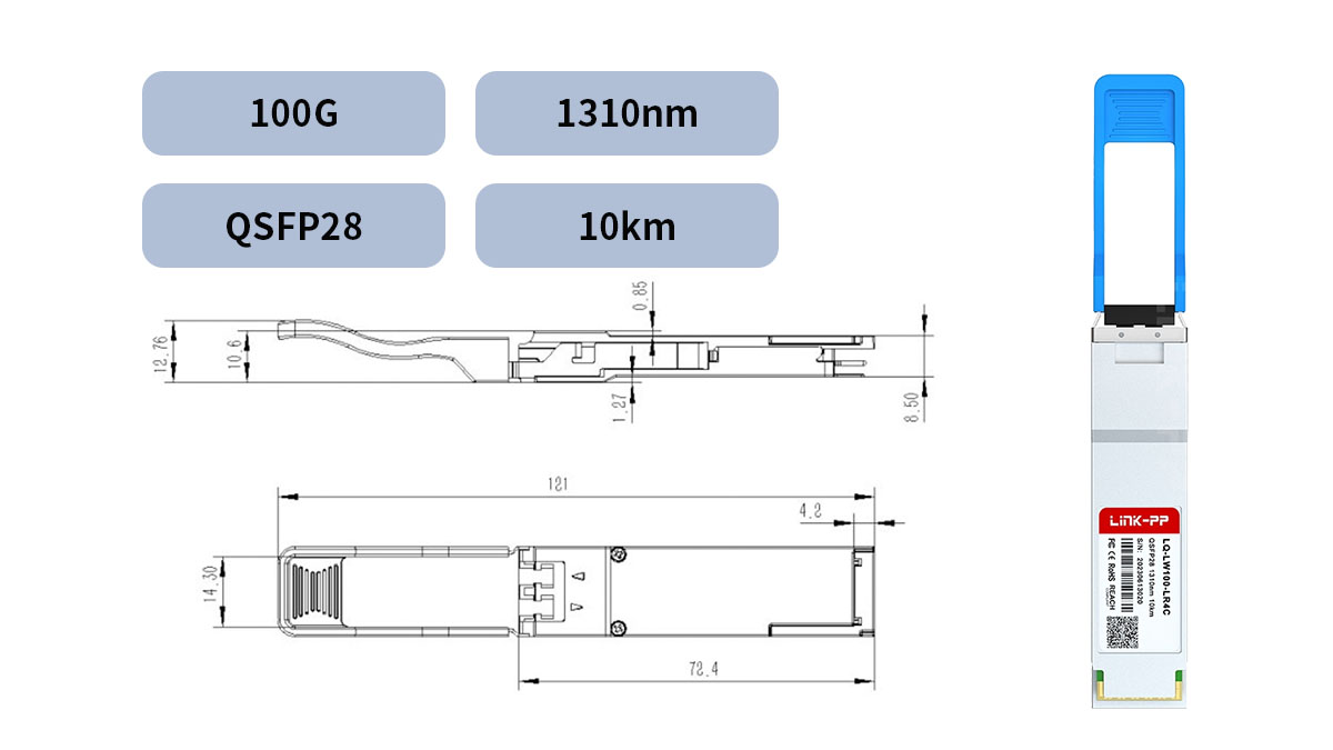
Form Factor Dynamics: Standardizing Across 100G and 400G Ports
Modern network hardware relies on highly standardized physical shapes and sizes to ensure different equipment brands work together seamlessly. LR4 optics are manufactured in compact, hot-swappable form factors that slide easily into industry-standard switch slots. This physical standardization allows data centers to scale their speeds from 100G up to 400G using the exact same underlying architecture.
The physical layout and port integration depend on these specific standards:
- QSFP28 standard: The reigning structural form factor for 100G LR4 connections.
- QSFP-DD design: The double-density interface is utilized for high-density 400G links.
- Hot-swappable builds: Modules can be replaced instantly without powering down switches.
- High-density spacing: Compact dimensions allow dozens of ports on a single switch row.
📃 Architecture Deep Dive: Deploying LR4 Optics in Long-Haul Topologies
Integrating long-range transceivers into a live data center layout requires strategic planning at the foundational transport layer. When bridging separate geographical locations, these modules must map precisely to core routing architectures to ensure line-rate data transmission without protocol overhead. Designing a clean physical topology ensures that LR4 optics maintain optimal optical signal-to-noise ratios (OSNR) across complex single-mode fiber pathways.
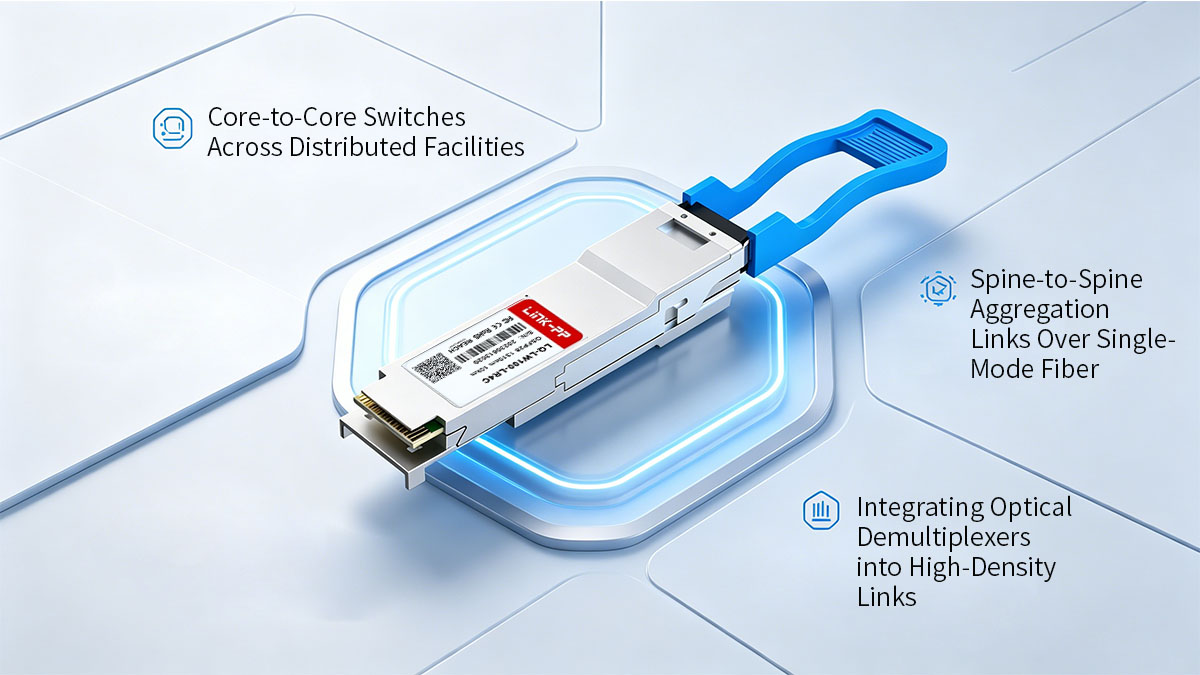
Core-to-Core Switches Across Distributed Facilities
Linking the primary core switches of separate data centers demands the highest level of physical-layer reliability and throughput available. Because core routing engines manage the aggregate data traffic for entire enterprise infrastructures, any latency or packet loss at this layer severely degrades distributed application performance. Deploying high-performance LR4 optics directly into these high-density core chassis creates a seamless, low-latency bridge operating over standard single-mode fiber infrastructure.
To ensure continuous availability, these core links are typically engineered using Link Aggregation Groups (LAG) split across redundant physical fiber paths. Utilizing LR4 optics in this tier eliminates the need for active transponder shelves, routing the optical signal directly from the switch port into the external plant. This native transport method minimizes propagation delay and simplifies the hardware stack by keeping the data entirely within the Ethernet domain.
Spine-to-Spine Aggregation Links Over Single-Mode Fiber
In modern non-blocking leaf-spine architectures, scaling east-west traffic patterns requires robust, high-speed interconnects across the distributed spine layer. When the physical footprint of a data center expands across multiple buildings, traditional multi-mode or short-reach multi-lane optics fail due to attenuation and modal dispersion. Integrating LR4 optics into the spine tier allows network architects to maintain a flat, low-latency fabric over single-mode fiber spans reaching up to 10km.
This long-reach capability ensures that distributed spine switches can exchange routing tables and state synchronization data at full wire speed. By leveraging single-mode fiber, these links remain immune to electromagnetic interference and experience minimal optical power loss over the extended run. The result is a highly predictable aggregation layer that supports massive multi-chassis EtherChannel configurations across the entire campus.
Integrating Optical Demultiplexers into High-Density Links
Maximizing the utilization of leased or dark fiber infrastructure requires combining multiple optical channels onto a single physical fiber pair. Passive optical multiplexers and demultiplexers are deployed at the boundaries of the 10km link to merge and separate these distinct data streams. Because LR4 optics utilize four tightly controlled LAN-WDM wavelengths within the O-band spectrum, they are uniquely suited for high-density passive optical filtering.
During deployment, network engineers must ensure the channel spacing of the thin-film filters inside the demultiplexer matches the exact IEEE specifications of the transceiver lasers. It is also critical to calculate the cumulative insertion loss introduced by these passive devices to avoid exhausting the transceiver's optical power budget. Proper link budget engineering guarantees that the LR4 optics deliver sufficient receiver sensitivity at the remote end of the fiber loop.
📃 Infrastructure Requirements for Maximum LR4 Optics Performance over 10km
Achieving flawless data transmission across a 10km span depends heavily on the quality of the underlying physical plant. Even the most advanced transceivers cannot overcome a poorly designed or degraded fiber infrastructure. Laying down a solid physical foundation ensures that LR4 optics maintain strong optical power levels and deliver error-free wire speeds.
Selecting the Right Grade of Single-Mode Fiber (OS2 vs. OS1)
Choosing between different grades of single-mode fiber is the first critical step when preparing your long-haul cabling route. While OS1 fiber is designed for indoor, short-reach campus applications, its high attenuation rates make it entirely unsuitable for long distances. Outdoor-rated OS2 fiber features a loose-tube construction that protects the glass from moisture and extreme temperature fluctuations.
To highlight the structural and performance differences between these two standards, consider the following quick-reference comparison:
| Feature / Metric |
OS1 Single-Mode Fiber |
OS2 Single-Mode Fiber |
| Primary Environment |
Indoor / Data Center Building |
Outdoor / Underground Conduit |
| Maximum Attenuation |
Around 1.0dB/km |
Around 0.4dB/km or lower |
| Optimal Distance |
Up to 2km |
Up to 10km and beyond |
| Cable Construction |
Tight-buffered layout |
Loose-tube breakout design |
Calculating the Impact of Splices and Patch Panels on the 10km Limit
Every single connection point along an outdoor fiber run introduces a small amount of signal loss known as insertion loss. Fusion splices, patch panels, and bulkhead adapters all absorb or reflect a fraction of the light emitted by LR4 optics. If a network engineer fails to account for these connection points, the accumulated loss can easily exhaust the transceiver's power budget long before the light reaches the 10km mark.
To prevent link degradation, a strict optical power budget calculation must be performed during the design phase. Each mechanical connector should ideally contribute no more than 0.5dB of loss, while clean fusion splices should remain below 0.1dB. Keeping a detailed log of every patch panel along the route ensures that your LR4 optics retain enough signal strength to be read accurately by the receiving switch.
Managing Dispersion and Attenuation Across Long Cable Runs
As light pulses travel down a 10km glass strand, they naturally experience attenuation, which is the gradual weakening of the light's intensity. Additionally, chromatic dispersion can cause different light frequencies to travel at slightly different speeds, blurring the data pulses by the time they reach their destination. Because LR4 optics utilize four distinct LAN-WDM wavelengths, managing these twin optical distortions is vital for maintaining network stability.
Fortunately, the specific wavelengths used by these modules sit right in the O-band spectrum, where single-mode fiber exhibits near-zero chromatic dispersion. However, severe cable bends or tight zip-ties inside patch enclosures can cause micro-bends that dramatically increase local attenuation. Keeping the fiber paths straight, clean, and physically protected allows LR4 optics to deliver consistent, zero-packet-loss performance over the maximum rated distance.
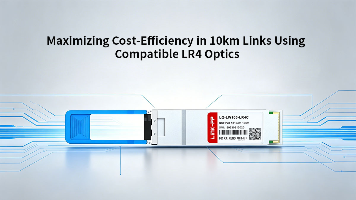
📃 Maximizing Cost-Efficiency in 10km Links Using Compatible LR4 Optics
Building a reliable long-haul infrastructure does not require exhausting an enterprise's entire technology budget. By exploring high-quality third-party compatible hardware alternatives, procurement teams can significantly reduce their initial network deployment expenses. Balancing capital savings with strict performance standards ensures that LR4 optics deliver maximum economic value without sacrificing operational stability.
Reducing Data Center CAPEX with Third-Party Modules
Deploying original equipment manufacturer (OEM) transceivers across hundreds of long-distance switch ports often leads to unsustainably high capital expenditures. Opting for certified compatible LR4 optics allows organizations to break free from vendor lock-in and acquire identical hardware capabilities at a fraction of the cost. These substantial upfront savings can then be redirected toward scaling physical fiber paths or upgrading core security systems.
Evaluating the Long-Term ROI of Enterprise-Grade LR4 Transceivers
While low-cost alternatives are attractive, investing in premium, tier-one compatible LR4 optics ensures long-term return on investment by minimizing network downtime. High-grade compatible transceivers use the same top-tier laser components as OEM models, guaranteeing a long operational lifespan over extended 10km runs. This strict adherence to build quality dramatically drops replacement rates and avoids the costly emergency troubleshooting cycles associated with generic, uncertified modules.
Optimizing Power Consumption and Cooling Costs in Dense Deployments
Operating dense rows of high-speed switches generates massive thermal loads, making energy efficiency a prime design metric for modern data center managers. Modern compatible LR4 optics are engineered with advanced low-power chipsets that draw significantly less electricity per port than older generational designs. Lowering the power draw per transceiver reduces the strain on facility cooling infrastructure, yielding substantial savings on monthly utility bills across multi-facility deployments.
📃 Guaranteeing Hardware Interoperability for LR4 Optics Solutions
Deploying third-party compatible transceivers requires complete assurance that the new hardware will integrate seamlessly with your existing switches and routers. Because different networking vendors utilize proprietary coding blocks, ensuring broad system compatibility prevents unexpected port lockouts and configuration errors. Establishing seamless multi-vendor cooperation allows LR4 optics to behave identically to original factory components from day one.
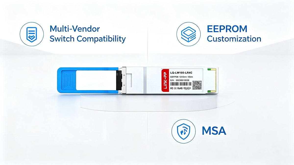
Multi-Vendor Switch Compatibility and EEPROM Customization
Many major networking brands program their switch operating systems to reject third-party hardware by checking for specific cryptographic signatures. To bypass this barrier, high-quality compatible LR4 optics undergo custom EEPROM flashing to perfectly mimic original manufacturer vendor codes.
This precise microcode tailoring ensures that the hosting switch recognizes the transceiver immediately and activates the port without throwing warning messages. Correct EEPROM customization guarantees that specialized properties like the Digital Diagnostic Monitoring function are reliable across diverse hardware platforms.
Validating Compliance with MSA (Multi-Source Agreement) Standards
The backbone of modern networking interoperability rests on Multi-Source Agreements, which define the exact physical and electrical boundaries for optical modules. By strictly adhering to these design standards, certified LR4 optics ensure absolute physical compatibility with any standard-compliant switch cage worldwide.
These strict engineering blueprints regulate everything from pin layouts to laser power levels across the 10km link. Following these standardized guidelines prevents structural damage to delicate ports and guarantees consistent signaling behavior regardless of the brand names on the chassis.
Seamless Upgrades: Mixing OEM and Certified Compatible Hardware
Modern data center expansions frequently require integrating newer, cost-effective components alongside existing legacy network infrastructure. Utilizing premium compatible LR4 optics lets network engineers mix third-party transceivers into optical links that connect directly to original OEM hardware.
This flexible deployment strategy eliminates the expensive and wasteful requirement of replacing perfectly functional factory components all at once. Maintaining steady, mixed-brand interoperability gives enterprise teams the freedom to scale out their 10km backbones on their own schedule.
📃 Best Practices for Installing and Maintaining 10km LR4 Optics Solutions
Implementing strict operational habits during the physical installation phase drastically lowers the chance of long-term fiber link failures. Because long-distance optical signals are highly sensitive to microscopic physical disruptions, handling procedures must be precise and consistent. Adhering to standardized maintenance workflows ensures that LR4 optics remain physically protected and perform at peak efficiency year after year.
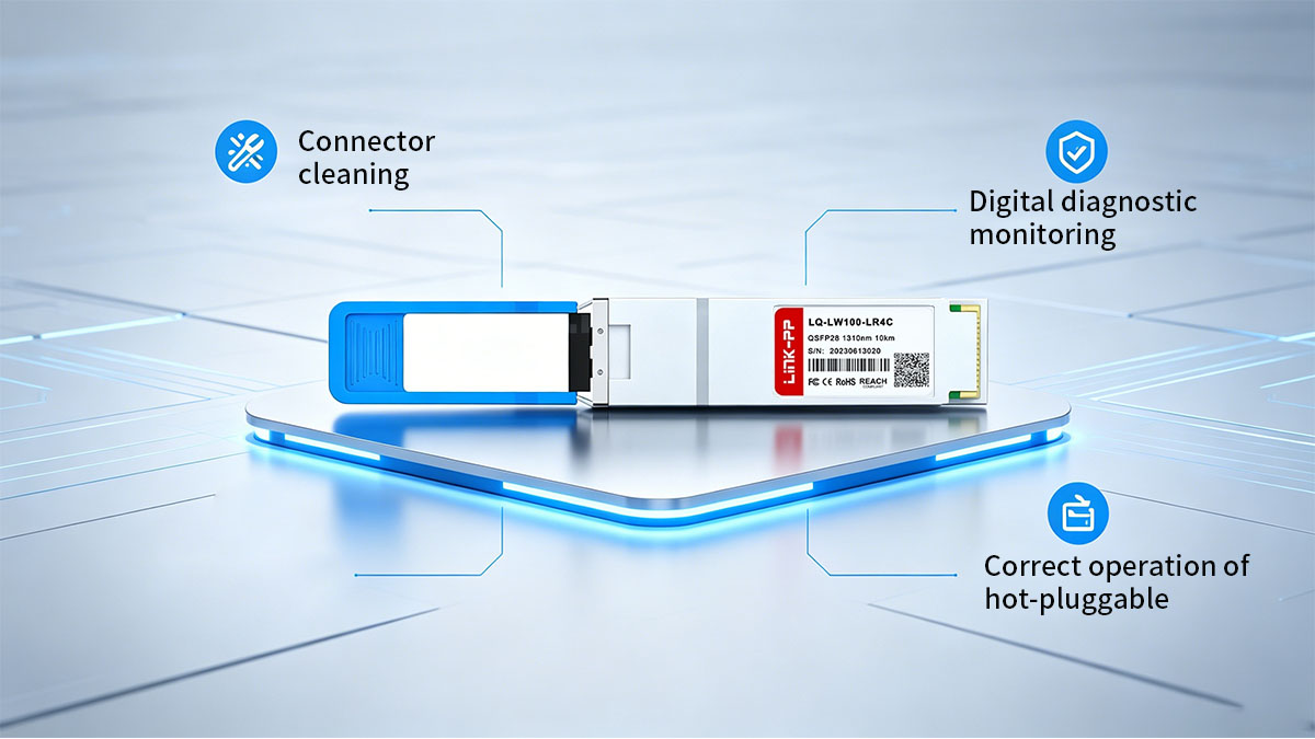
Strict Cleaning Protocols for LC Connectors in Long-Haul Links
Microscopic dust particles sitting on an LC connector tip can completely block or scatter the concentrated light lasers used by long-reach transceivers. Forcing a contaminated fiber connector into a clean port can also permanently scratch the internal glass lens of your LR4 optics.
Adhering to the following physical cleaning rules will keep your fiber pathways completely clear:
- Inspect first: Use a fiber scope to look for hidden dirt before plugging in.
- Use dry cleaners: Utilize specialized fiber optic click-cleaners for routine dust removal.
- Avoid bare skin contact: Never touch the exposed ferrule tip with your fingers.
- Cap immediately: Install protective rubber dust covers the moment a cable is unplugged.
Monitoring TX/RX Power Levels via Digital Diagnostic Monitoring (DDM)
Digital Diagnostic Monitoring (DDM) is an embedded software feature that provides real-time visibility into the physical health of your optical link. Tracking these metrics allows network teams to catch gradual laser degradation or cable damage before it triggers a complete network blackout.
The following key operational metrics should be monitored continuously through your switch operating system:
- TX power: Shows the exact strength of the light leaving the transmitter laser.
- RX power: Measures the remaining light level received at the opposite end.
- Operating temperature: Watches for internal overheating inside dense switch chassis.
- Supply voltage: Checks that the switch port is delivering stable electrical power.
Hot-Swapping Safety and Proper Handling in Live Production Environments
Modern network switches allow technicians to insert or remove transceivers instantly without interrupting traffic on adjacent ports. However, handling LR4 optics in a live environment requires caution because the invisible infrared lasers can cause permanent eye damage if looked at directly.
Following these safety and handling guidelines protects both the data center technician and the delicate hardware:
- Never stare into ports: Assume every open optical slot has an active laser emitting light.
- Use the bale clasp: Always unlock the transceiver using its integrated mechanical pull-tab.
- Avoid force: Slide the module smoothly into the port until it clicks firmly into place.
- Wear static wristbands: Ground yourself to prevent static electricity from frying internal circuits.
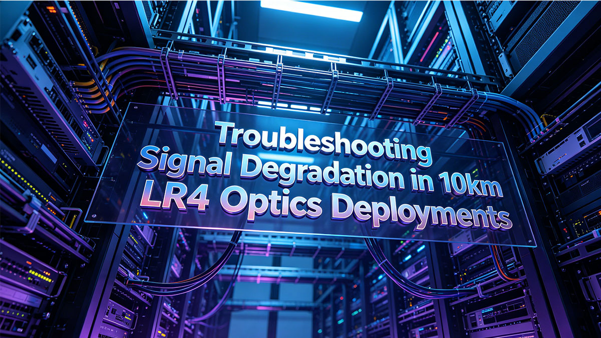
📃 Troubleshooting Signal Degradation in 10km LR4 Optics Deployments
Even with meticulous planning, long-haul fiber links can encounter physical disruptions that weaken light signals over time. When performance issues arise, network teams must systematically isolate whether the problem sits within the fiber glass or the transceiver hardware itself. Rapidly identifying the root cause of signal degradation keeps critical 10km pathways stable and minimizes packet drop rates.
Resolving High Bit Error Rates (BER) over Long Distances
A high Bit Error Rate (BER) indicates that data frames are becoming corrupted as they travel down the 10km single-mode fiber line. This mathematical corruption usually occurs when the optical signal becomes too weak for the receiving LR4 optics to distinguish between data bits.
Network engineers can resolve climbing error rates by focusing on these essential hardware isolation steps:
- Check DDM thresholds: Review the interface logs to verify if incoming light power is too low.
- Inspect for micro-bends: Look for overly tight cable ties or sharp kinks in the fiber trays.
- Clean the patch points: Wipe down intermediate connections to instantly clear away debris.
- Test with a loopback: Plug a local test loop into the module to isolate switch port errors.
Identifying Optical Insertion Loss and Reflection Points
Optical insertion loss happens when the total power of the laser light drops unexpectedly between the transmitter and the receiver. Additionally, back-reflections can bounce light right back into the LR4 optics transmitter, causing severe laser instability.
Pinpointing these hidden physical flaws along a 10km run requires using specialized diagnostic equipment:
- Run an OTDR test: Use an Optical Time-Domain Reflectometer to map the entire fiber run.
- Locate bad splices: Scan the OTDR graph to find individual fusion splices exceeding 0.1dB loss.
- Check bulkhead adapters: Inspect physical coupling sleeves for interior cracking or alignment tilt.
- Replace damaged patch cables: Swap out old yellow single-mode patch cords showing high loss.
How to Fix Link Flaps Caused by Wavelength Drift
Link flapping occurs when an interface rapidly transitions between an active "up" state and a disconnected "down" state. For LR4 optics, this frustrating issue can be triggered by internal thermal breakdown, which causes the laser's tightly controlled LAN-WDM wavelengths to shift out of their correct grids.
Technicians can stabilize a flapping link by executing these targeted hardware troubleshooting steps:
- Monitor transceiver temperature: Use the switch software to verify if the module is overheating.
- Verify chassis cooling: Check that the surrounding switch fans and air filters are clear.
- Firmware updates: Ensure the switch operating system is running the latest recommended driver stack.
- Swap the module: Replace the transceiver if the internal laser continues to drift off frequency.
Conclusion: Optimizing 10km Long-Haul Infrastructure with LR4 Optics
Building a reliable 10km network backbone requires a careful balance of high-quality fiber infrastructure, proper architectural planning, and stable hardware. Deploying premium LR4 optics ensures your data center interconnects maintain consistent wire speeds and zero packet loss over long distances. By adhering to industry best practices and strict installation standards, network teams can maximize long-term operational efficiency.
When you are ready to scale out your long-haul networking capacity, choosing certified, high-performance transceivers is crucial for reducing overhead costs. Explore the premium selection of compatible optical modules available at the LINK-PP Official Store to find the ideal LR4 optics solutions tailored for your multi-vendor environment. Investing in these enterprise-grade long-reach modules guarantees maximum hardware interoperability and long-term signal stability across your entire campus infrastructure.


