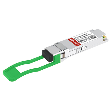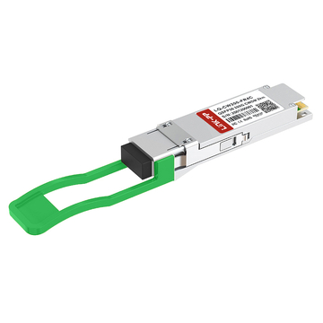
Are you scaling up high-performance computing clusters or AI data centers and struggling to maintain low latency at 200Gbps speeds? Deploying high-density optical hardware like the MMA1T00-HS QSFP56 MMF transceiver is essential for achieving optimal throughput across short-reach multimode fiber interconnects. Understanding the underlying physical-layer characteristics of this optical module ensures your infrastructure operates at peak performance without costly link degradation.
How can network engineers verify whether a specific transceiver meets their strict optical power budgets, thermal dissipation limits, and system compatibility requirements? Evaluating every electrical signal parameter, mechanical form factor standard, and real-time monitoring capability is key to preventing network bottlenecks. By thoroughly reviewing these detailed hardware parameters, you can build a stable, scalable InfiniBand network optimized for modern enterprise workloads.
↘️ Primary Optical Specs of the MMA1T00-HS Multimode Transceiver
The optical performance of a high-speed module relies heavily on how effectively light signals are generated, modulated, and received across multimode fiber. Key parameters like operating wavelength, modulation schemes, launch power thresholds, and receiver sensitivity directly define signal integrity and link stability in demanding 200Gbps InfiniBand deployments.
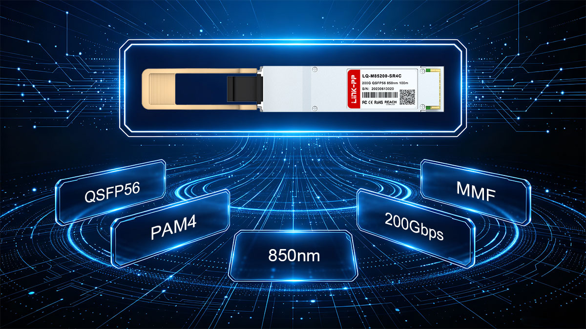
Operating at the 850nm VCSEL Central Wavelength
The MMA1T00-HS multimode transceiver relies on an array of 850nm Vertical-Cavity Surface-Emitting Lasers (VCSEL) as its primary light source. VCSEL technology is ideal for short-reach, multi-lane applications because it offers high modulation bandwidth with low power consumption.
Operating within the 840nm to 860nm optical window matches the modal bandwidth profile of standard multimode fibers like OM3 and OM4. This tight wavelength center minimizes chromatic dispersion, helping preserve clean optical pulses across parallel fiber strands.
Utilizing 50G PAM4 Optical Modulation Schemes
To achieve a total throughput of 200Gbps, the transceiver processes four parallel optical lanes running at 50Gbps each using PAM4 (4-level Pulse Amplitude Modulation). Unlike traditional NRZ signaling that transmits one bit per clock cycle, PAM4 encodes two bits of data into four distinct optical amplitude levels.
This doubling of spectral efficiency allows the module to handle higher data densities without doubling the physical baud rate. By operating at roughly 26.56GBd per lane, it maintains high signal clarity while keeping jitter and signal attenuation within strict operational limits.
Measuring Average Launch Optical Power Boundaries
The average launch optical power of the transmitter defines the intensity of the light signals fed into the multimode fiber plant. For each lane, the typical average launch power stays between a lower boundary of around -6.5dBm and a maximum safety limit of +4.0dBm.
Maintaining these bounds prevents two distinct issues: overly low launch power leads to poor signal-to-noise ratios, while excessively high power overloads the receiving optics on the opposing switch port. These balanced power boundaries ensure consistent link margins across short-distance interconnects.
Assessing Receiver Optical Sensitivity Thresholds
Receiver sensitivity measures the minimum optical power required by the photodetector to accurately reconstruct transmitted PAM4 data signals without incurring uncorrectable bit errors. The receiver photodiode in this transceiver operates down to a sensitivity threshold near -7dBm (OMA).
Because 50G PAM4 signals feature smaller eye openings and lower noise margins than older NRZ formats, strong receiver sensitivity is crucial. Paired with Forward Error Correction (FEC) on the host switch, this sensitivity floor helps ensure reliable packet delivery across the full length of the optical path.
↘️ What Electrical Specifications Drive MMA1T00-HS Operating Performance
Behind the optical conversion, the electrical interface serves as the primary bridge between the host system SerDes and the physical transceivers. Parameters such as signal modulation, impedance matching, power budget allocations, and voltage stability govern how cleanly data transfers across the switch system board.

Analyzing 200Gbps PAM4 Electrical Interface Signals
The electrical interface of the MMA1T00-HS 200GBASE-SR4 module operates using four high-speed electrical lanes configured for 50G PAM4 (26.5625GBd) signaling. This host-side 4x50Gbps electrical architecture matches the line-side optical signaling rate, eliminating the need for complex gearbox conversions inside the optical transceiver.
By maintaining native PAM4 signaling across the electrical connector, the module minimizes processing latency and internal power dissipation. Advanced host equalization techniques, such as continuous time linear equalization (CTLE) and decision feedback equalization (DFE), are applied to clean up signal loss and inter-symbol interference across the host PCB traces.
Measuring Differential Input and Output Impedance Values
Impedance matching across high-speed differential traces is critical to preventing signal reflection, return loss, and jitter in 200G networks. Maintaining strict differential impedance limits ensures that high-frequency electrical signals flow smoothly between the host switch SerDes and the optical driver ICs without degradation.
The table below outlines the core electrical impedance parameters and target tolerance limits specified for this optical transceiver interface:
| Parameter | Nominal Value | Standard Range / Tolerance | Impact on Signal Integrity |
| Differential Input Impedance | 100Ω | 90Ω to 110Ω | Prevents signal reflection on high-speed transmit lanes |
| Differential Output Impedance | 100Ω | 90Ω to 110Ω | Ensures clean signal delivery to the host receiver SerDes |
| Differential Return Loss (SDD11/SDD22) | -10dB | Meets IEEE 802.3cd limits | Reduces high-frequency energy bounces across the connector |
| Common Mode Return Loss (SCC11) | -3dB | Meets SFF-8679 limits | Suppresses unwanted electromagnetic interference (EMI) noise |
Operating within these defined impedance boundaries prevents impedance discontinuities at the card-edge interface. Consistent 100-ohm differential matching protects low-voltage PAM4 signal eyes, enabling error-free transmission across the physical host interface.
Evaluating Power Consumption Metrics per Module
Power consumption directly dictates thermal management design and operational costs within high-density switch chassis. The MMA1T00-HS QSFP56 optical transceiver is engineered to maintain low power draw, typically consuming less than 5.0W under full 200Gbps line-rate operation.
By keeping power consumption well within the standard QSFP56 Power Class boundaries, the module avoids placing excessive thermal stress on host switch backplanes. This efficient power profile enables network engineers to fully populate high-density Quantum HDR InfiniBand switches without exceeding system cooling limits.
Verifying 3.3V Power Supply Voltage Requirements
Stable power delivery is essential for maintaining accurate laser biasing and digital diagnostic monitoring inside the transceiver. The module relies on a standard 3.3V DC power rail supplied directly through the host QSFP56 connector interface.
To ensure uninterrupted operation, the electrical interface tolerates an operational voltage window between 3.135V and 3.465V (±5% tolerance). Onboard power supply filtering networks suppress high-frequency ripple voltage from the host card, protecting sensitive optical drivers and keeping output power levels rock solid.
↘️ How Do Form Factor Specs Define the MMA1T00-HS Mechanical Design
Mechanical form factor specifications establish the precise physical dimensions, connector interfaces, and structural latching mechanisms required for high-density networking hardware. The physical design of the module guarantees reliable mechanical fit, effortless hot-swapping, and seamless physical integration within modern switch faceplates.
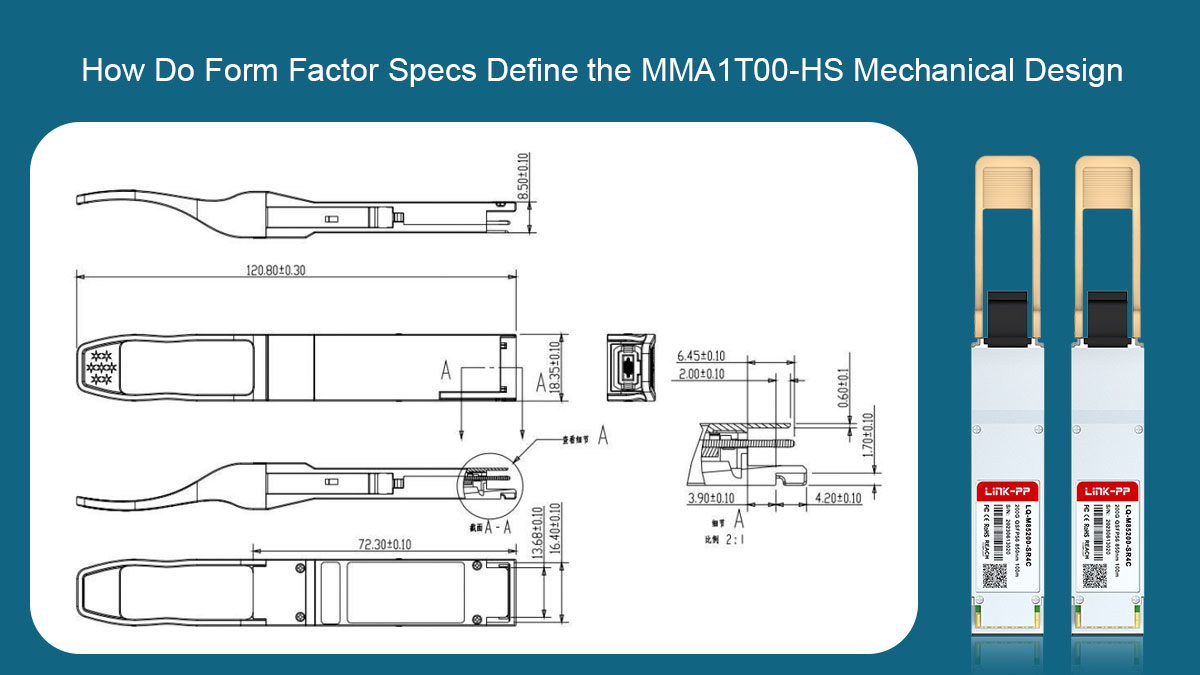
Adhering to the QSFP56 SFF-8665 Physical Standard
The MMA1T00-HS 200G optical module adheres strictly to the SFF-8665 specification, which governs the physical envelope and mechanical footprint of the Quad Small Form-factor Pluggable (QSFP56) module. This standardization guarantees exact mechanical mating with any compliant cage assembly on host switches and network adapters.
By following standardized SFF-8665 shell dimensions, the transceiver maintains precise alignment for its internal electrical card-edge contacts. This strict mechanical compliance eliminates physical fitment issues, ensuring seamless hot-pluggable deployment across high-performance computing environments.
Utilizing MPO-12 Optical Connector Interfaces
The physical optical interface relies on a standardized MPO-12 male connector with alignment pins to connect directly with multi-fiber trunk cables. This interface enables parallel optical transmission by aggregating eight active fiber channels into a single compact receptacle on the transceiver faceplate.
Key structural aspects defining this MPO-12 module receptacle include:
- 8-fiber active layout: Utilizes 4 transmit and 4 receive channels while leaving the 4 center positions unused.
- Precision alignment pins: Features fixed metal guide pins inside the receptacle to ensure exact optical alignment with female cable connectors.
- Integrated receptacle latching: Provides a secure mechanical snap-fit that holds the optical connector firmly in place during active link operation.
By using this MPO-12 receptacle design, the optical transceiver achieves high-density fiber connectivity within a compact physical layout. Direct alignment between internal laser arrays and external fiber cores maintains low insertion loss and protects the optical sub-assembly during repeated cable insertions.
Incorporating Pull-tab Latching Mechanisms for Quick Removal
Field maintenance and cable management require fast, tool-less insertion and extraction of optical transceivers from crowded switch chassis. The module incorporates an ergonomically designed pull-tab latching mechanism that releases internal retention clips upon extraction.
This color-coded pull-tab provides technicians with an intuitive grip for straightforward module disengagement. The mechanical latch mechanism ensures securely locked placement during normal operation while preventing damage to the switch cage when removing the module.
Optimizing Module Dimensions for High Density Port Layouts
High-density switch designs demand precise module width and height profiles to maximize the number of ports per rack unit. The standardized QSFP56 dimensions allow switches to house up to 32 or 36 ports across a standard 1U faceplate layout.
Optimized mechanical housing parameters leave uniform air gaps between adjacent transceiver cages for unhindered airflow. This spatial optimization supports maximum port density while allowing effective chassis-level cooling across dense 200Gbps InfiniBand deployments.
↘️ Which Distance Specs Apply to the MMA1T00-HS Fiber Connectivity
Optical reach parameters dictate the physical boundaries for deploying high-speed interconnects across data center halls and server racks. Transmission distances depend heavily on the modal bandwidth of the selected multimode fiber cabling and the total optical loss permitted along the optical path.
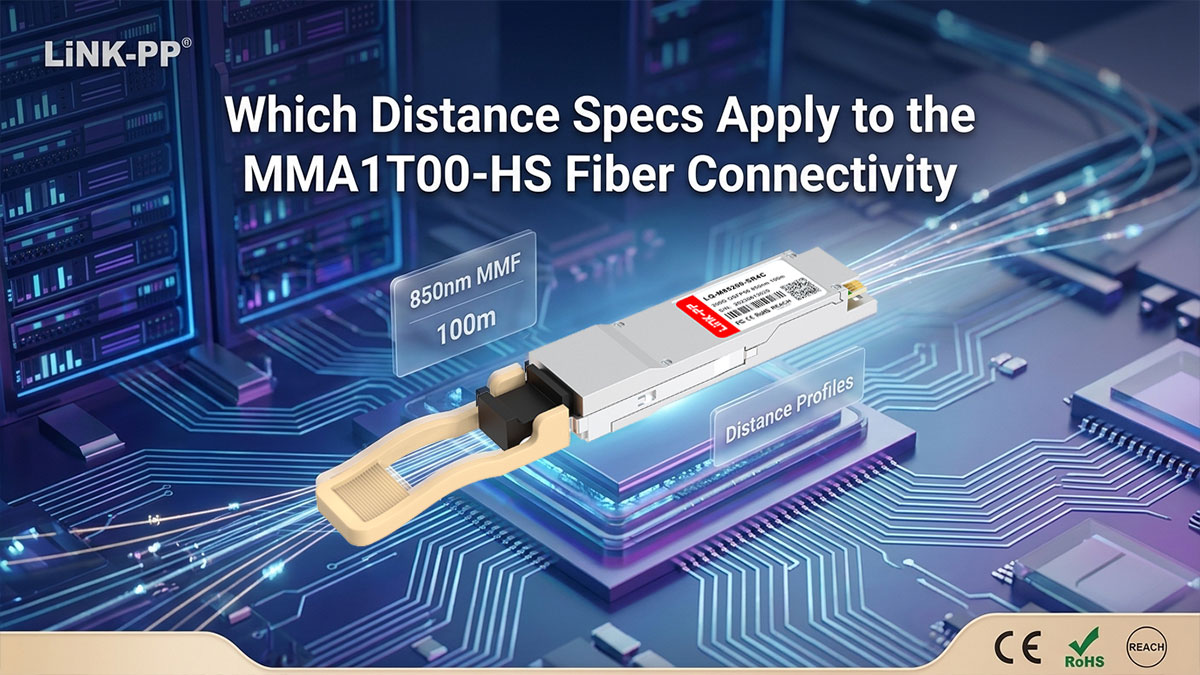
Supporting up to 70m over OM3 Multimode Fiber
When deployed with legacy OM3 multimode fiber optic cables, the MMA1T00-HS transceiver module supports reliable 200Gbps transmission distances up to 70m. OM3 cabling offers an effective modal bandwidth of 2000 MHz·km at the 850nm operating wavelength.
Because 50G PAM4 signals are more susceptible to inter-symbol interference caused by modal dispersion over longer distances, 70m represents the safe operational boundary for OM3 infrastructure. This distance capability makes the transceiver an excellent choice for intra-rack connections and adjacent rack rows using existing OM3 fiber plants.
Reaching up to 100m Using OM4 & OM5 Multimode Fiber
Upgrading the optical infrastructure to OM4 or OM5 multimode fiber extends the maximum transmission reach of the module to 100m. OM4 and OM5 fibers deliver a higher effective modal bandwidth of 4700 MHz·km, significantly reducing modal dispersion at high data rates.
This 100m reach provides full coverage for top-of-rack (ToR), end-of-row (EoR), and middle-of-row (MoR) architectures in modern high-performance computing centers. Utilizing higher-grade OM4 or OM5 cabling ensures crisp PAM4 eye diagrams and maximizes bit-error-rate performance across maximum link spans.
Calculating Maximum Allowable Link Insertion Loss Budgets
The total allowable link insertion loss budget for the transceiver is typically capped at around 1.9dB over standard multimode fiber paths. This optical power budget accounts for total attenuation caused by fiber core attenuation, optical patch panel connections, and mechanical splices.
Network planners must carefully tally the loss introduced by each MPO connector mating — typically 0.2dB to 0.35dB per interface — to avoid exceeding the threshold. Staying within this 1.9dB loss budget guarantees that sufficient optical power reaches the receiver photodiodes to maintain error-free 200Gbps InfiniBand throughput.
↘️ Environmental Operating Specs for Safe MMA1T00-HS Deployment
Environmental operating specifications define the physical surrounding limits within which optical hardware can run continuously without component degradation or link errors. Parameters covering thermal range, ambient humidity, and active chassis airflow ensure stable laser operation and long-term hardware durability.

Maintaining Commercial Operating Temperature Limits from 0 to 70°C
The MMA1T00-HS 200G QSFP56 module is rated for a standard commercial operating temperature range of 0°C to 70°C (32°F to 158°F) measured at the external module case. Maintaining internal optical components within these thermal boundaries prevents wavelength drift and safeguards the sensitive internal VCSEL driver circuitry.
If internal operating temperatures exceed the 70°C threshold, optical output power can drop and bit error rates increase significantly. Operating strictly within this defined commercial temperature window guarantees consistent 200Gbps PAM4 signaling across demanding data center deployment environments.
Managing Storage Temperature Tolerances During Transit
Before active installation or during spares inventory storage, the module withstands non-operational storage temperatures ranging from -40°C to 85°C (-40°F to 185°F). This broad storage envelope protects internal soldered components, optical lenses, and semiconductor dies from thermal expansion damage during transit and warehousing.
Ensuring storage facilities and transport conditions remain within these non-operating limits preserves internal optical alignment. Proper thermal handling prior to installation guarantees that the transceiver meets factory specifications immediately upon host slot insertion.
Operating within Non-Condensing Relative Humidity Ranges
Humidity control prevents moisture accumulation inside the optical module housing, which can distort laser beam transmission or short internal electrical traces. The transceiver supports safe operation within a relative humidity range of 5% to 85% (non-condensing).
Maintaining non-condensing environmental conditions protects sensitive electrical contacts and optical fiber end-faces from moisture damage. Strict humidity boundaries prevent condensation spikes caused by rapid temperature fluctuations inside server rooms and switch corridors.
Dissipating Thermal Loads Efficiently Inside Switch Chassis
Efficient thermal management inside high-density switch cages relies on adequate system airflow to draw heat away from the transceiver casing. The compact QSFP56 metal enclosure is engineered to conduct internal operational heat directly toward switch-driven forced air channels.
Proper chassis fan speed profiles and clear airflow paths ensure heat generated by the internal 200G DSP and laser driver dissipates quickly. Effective thermal dissipation keeps individual port temperatures balanced, preserving system-wide reliability in fully populated Quantum HDR InfiniBand switches.
↘️ What Diagnostic Specs Are Built Into the MMA1T00-HS Module
Integrated telemetry capabilities enable network managers to evaluate physical-layer performance and detect potential optical link anomalies before outages occur. Built-in diagnostic functions offer real-time visibility into internal operational health across active 200Gbps InfiniBand connections.
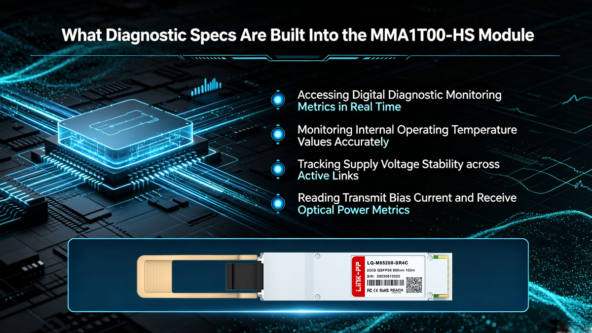
Accessing Digital Diagnostic Monitoring Metrics in Real Time
The MMA1T00-HS QSFP56 multimode module incorporates Digital Diagnostic Monitoring (DDM), also known as Digital Optical Monitoring (DOM), via an internal microcontroller compliant with the SFF-8636 management interface standard. This embedded system continuously measures key physical parameters and exposes them to the host switch firmware over an I²C two-wire management interface.
The core operational parameters reported in real time through the DDM interface include:
- Operating temperature: Tracks real-time thermal conditions inside the module housing.
- Supply voltage: Monitors the internal 3.3V DC power rail stability.
- Laser bias current: Measures the driving current applied across each VCSEL channel.
- Tx optical power: Calculates optical launch power emitted by each individual laser.
- Rx optical power: Detects incoming optical power levels received from the fiber link.
Continuous polling of these diagnostic parameters enables proactive network maintenance across high-density computing environments. System administrators can set automated alarm and warning thresholds in the host OS to trigger early warnings when operational parameters drift beyond nominal limits.
Monitoring Internal Operating Temperature Values Accurately
Accurate internal temperature sensors embedded inside the transceiver monitor thermal conditions directly adjacent to the laser diode drivers. Real-time thermal telemetry prevents silent performance drops caused by localized airflow blockages or fan failures inside switch chassis.
When internal temperatures approach upper operational boundaries, the host system reads DDM register flags to initiate alert logs or adjust chassis cooling speeds. Continuous thermal tracking ensures long-term VCSEL reliability and prevents uncorrectable bit errors caused by thermal wavelength drift.
Tracking Supply Voltage Stability across Active Links
Voltage telemetry circuits continuously track the 3.3V DC supply rail delivered from the host board directly to internal optical ICs. Monitoring real-time voltage levels ensures that transceiver components receive stable power during heavy traffic bursts and system-wide load fluctuations.
If power supply noise or voltage drops occur at the card-edge connector, DDM flags trigger system alerts before power drops cause optical bit errors. This voltage monitoring capability safeguards link stability across high-port-density 200Gbps InfiniBand switch deployments.
Reading Transmit Bias Current and Receive Optical Power Metrics
Per-lane optical telemetry tracks transmitter health and incoming signal strength across all four 50G PAM4 channels independently. Reading laser bias current reveals physical laser aging or driver degradation over time, allowing planned module replacements before catastrophic failure occurs.
Simultaneously, received optical power metrics verify link attenuation levels and optical end-face cleanliness along the fiber path. Monitoring Rx power thresholds ensures that incoming optical signals remain safely within photodetector sensitivity limits, guaranteeing error-free transmission across multimode fiber interconnects.
↘️ Which System Compatibility Specs Support MMA1T00-HS Deployment
System compatibility specifications ensure seamless integration and plug-and-play interoperability across high-performance computing hardware platforms. Verifying hardware, firmware, and speed mode support guarantees reliable optical connectivity within native NVIDIA InfiniBand fabric architectures.

Interfacing with Quantum HDR InfiniBand Switches
The MMA1T00-HS 200GBASE-SR4 optical module is purpose-built to interface directly with Quantum HDR InfiniBand switch platforms. Full hardware compatibility ensures that switch firmware instantly recognizes module EEPROM management data for automated port configuration and diagnostic tracking.
Plugging this optical transceiver into Quantum switch cages activates optimized physical-layer signaling and forward error correction (FEC) profiles. This native hardware integration maintains ultra-low latency and error-free line-rate performance across dense HPC switch backplanes.
Connecting to ConnectX-6 HDR Network Adapter Cards
In addition to switch-side deployments, the transceiver integrates seamlessly into ConnectX-6 HDR host channel adapters (HCAs). Installing the module on adapter cards provides high-speed server-to-switch interconnects for compute nodes and AI storage arrays.
The physical and electrical design aligns perfectly with ConnectX-6 thermal and power distribution parameters. This tight pairing delivers maximum throughput and low CPU overhead for compute-intensive workloads running across InfiniBand fabrics.
Configuring Native 200Gbps Point-to-Point HDR Links
When deployed between two 200G HDR ports, the transceiver operates in a native point-to-point mode delivering full 200Gbps bidirectional throughput. In this primary configuration, all four 50G PAM4 lanes function as a single unified high-speed logical link.
Native 200Gbps operation provides maximum bandwidth with minimal protocol overhead for latency-sensitive applications. Using straight MPO-12 to MPO-12 fiber trunk cables enables simple, reliable point-to-point connections across rack rows.
Executing Breakout Routing to Dual 100Gbps HDR100 Endpoints
For flexible topology designs, the optical transceiver supports breakout configurations that split a single 200G port into two independent 100G HDR100 links. In breakout mode, the module's four active optical lanes divide into two 2x50G PAM4 logical channels.
Connecting an MPO-12 to 2x MPO-12 splitter cable allows one switch port to link directly to two separate 100G ConnectX-6 HDR100 adapters. This breakout routing capability doubles switch port density and optimizes overall cable infrastructure costs in large-scale data center fabrics.
↘️ Summary: Key Takeaways on MMA1T00-HS Specs and Deployment

Understanding the complete hardware specifications of the MMA1T00-HS QSFP56 200G module ensures seamless deployment across high-performance computing clusters and demanding AI workloads. From 50G PAM4 optical signaling to standardized QSFP56 mechanical features, every specification plays a critical role in maintaining ultra-low latency and maximum data throughput.
Key architectural highlights that define this optical transceiver include:
- High-speed 50G PAM4 modulation: Delivers 200Gbps total throughput across four parallel optical lanes.
- Standardized QSFP56 form factor: Ensures seamless mechanical fit and optimal chassis thermal dissipation.
- Flexible short-reach connectivity: Reaches up to 70m over OM3 and 100m over OM4/OM5 multimode fiber.
- Real-time DDM telemetry: Tracks voltage, temperature, bias current, and optical power to prevent network downtime.
- Versatile HDR topology support: Operates in native 200G mode or breakout 2x100G HDR100 configurations.
For data center operators seeking a cost-effective alternative without compromising physical-layer performance, high-quality third-party optical modules offer full system compatibility. The LINK-PP LQ-M85200-SR4C 200G QSFP56 module serves as a reliable compatible equivalent to the MMA1T00-HS, delivering identical optical specifications, low power consumption, and seamless interoperability across Quantum HDR switches and ConnectX-6 adapters.
Ready to optimize your 200G InfiniBand network infrastructure with reliable optical hardware? Visit the LINK-PP Official Store to explore fully tested compatible transceivers, request detailed spec sheets, and consult our customer service team to find the exact optical transceiver modules for your network requirements.