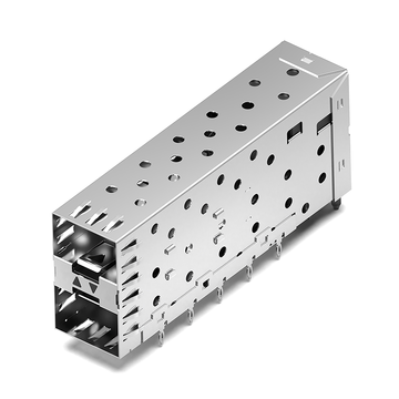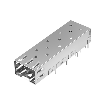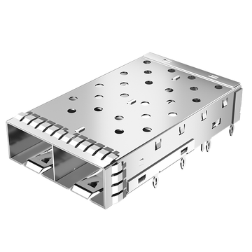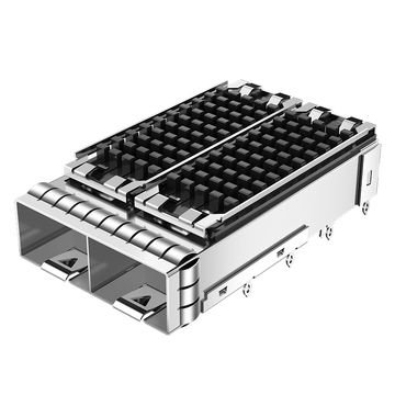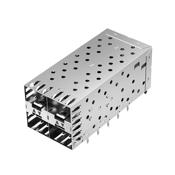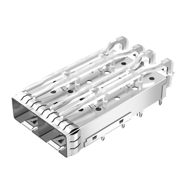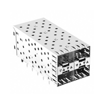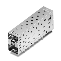
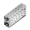
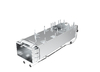
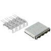

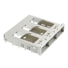

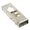
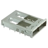
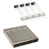




SFP cages are essential mechanical and electrical interface components in networking equipment, including Ethernet switches, routers, servers, and network interface cards. They provide a standardized enclosure for Small Form-Factor Pluggable (SFP) transceivers while supporting mechanical retention, electromagnetic interference (EMI) shielding, grounding, and thermal management.
However, selecting an SFP cage involves more than matching its external appearance. Engineers must understand cage mounting pins, the 20-pin electrical connector, transceiver package dimensions, PCB footprints, and mounting configurations. Confusing these specifications can result in mechanical interference, incorrect PCB layouts, poor grounding, or installation problems.
This guide explains the essential technical details and practical selection considerations for SFP cages, covering:
-
SFP cage structures, mounting pins, and electrical connector pin assignments.
-
Standard SFP transceiver package dimensions and cage mechanical specifications.
-
PCB footprints, port configurations, and mounting methods.
-
EMI shielding, thermal management, and common installation issues.
-
LINK-PP SFP cage, product specifications, and selection considerations.
By understanding these factors, hardware engineers can identify suitable SFP cage assemblies, verify mechanical compatibility, and improve the reliability of networking equipment designs.
What Is an SFP Cage and How Does It Work?
An SFP cage is a metal enclosure mounted on a host PCB that accommodates an SFP transceiver. It provides mechanical support, electromagnetic shielding, and a standardized insertion interface for hot-pluggable optical or copper modules.
SFP cages are commonly used in:
-
Ethernet switches and routers.
-
Data center servers and network interface cards.
-
Fiber channel storage equipment.
-
Enterprise networking hardware.
-
Telecommunications and industrial networking systems.
Understanding the cage structure helps distinguish its mechanical mounting features from the electrical connector that communicates with the transceiver.
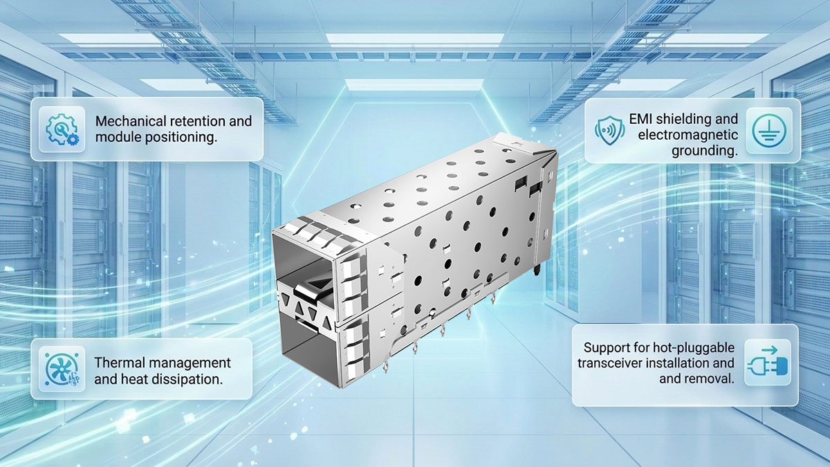
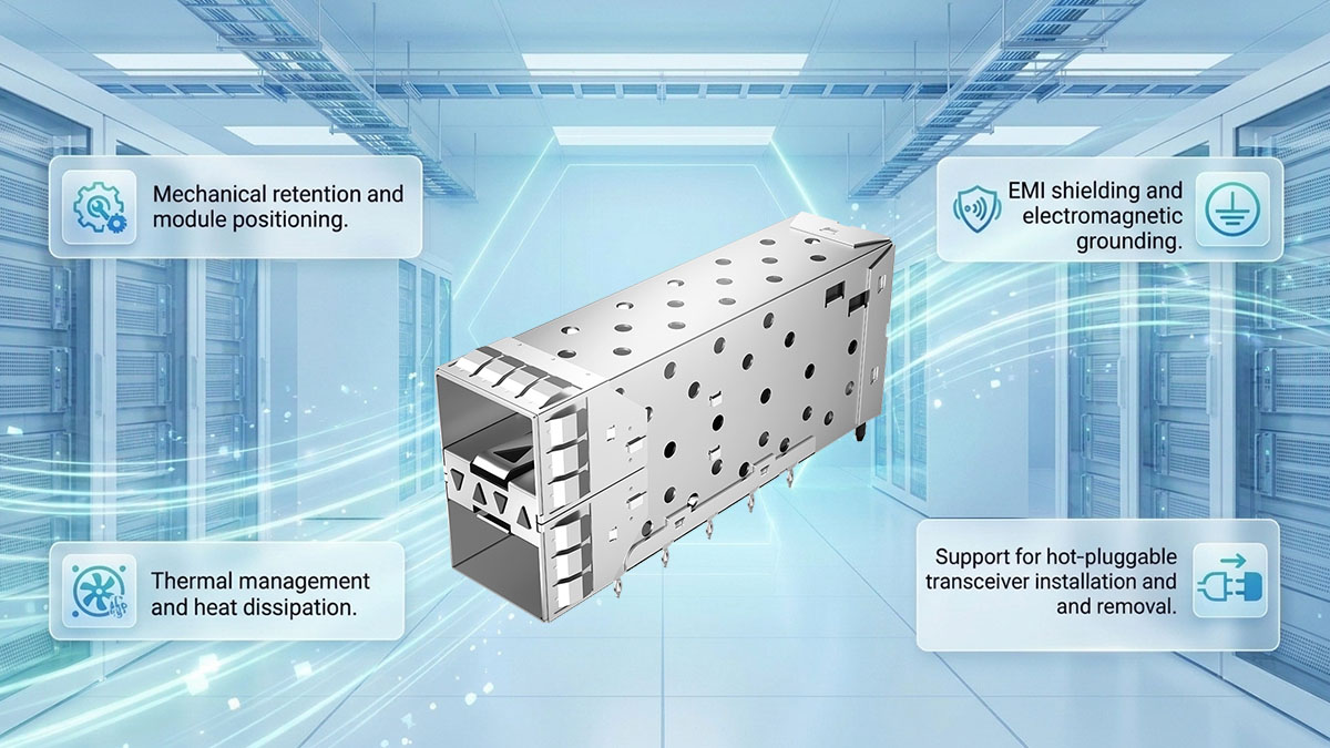
Definition and Primary Functions of an SFP Cage
An SFP cage is a conductive metal housing designed to receive and retain an SFP-family transceiver. It is typically installed at the front edge of a host PCB and aligned with an opening in the equipment's front panel.
Its primary functions include:
-
Mechanical retention: Holds the transceiver in the correct position and supports insertion, removal, and latch engagement.
-
EMI shielding: Provides a conductive enclosure that helps contain electromagnetic emissions and reduce susceptibility to external interference.
-
Grounding: Establishes electrical contact between the cage, host chassis, and associated grounding structures.
-
Thermal management: Supports heat transfer from the transceiver to the surrounding environment, sometimes through integrated or external heatsinks.
-
Hot-plug support: Provides a standardized mechanical interface for inserting and removing compatible transceivers without shutting down the entire networking device.
The cage is therefore an important part of the host-side interface, not simply a protective metal cover.
Main Components of an SFP Cage Assembly
An SFP cage assembly consists of several mechanical and electrical elements that work together to support the transceiver and maintain reliable connections.
The main components include:
-
Metal cage body: Forms the enclosure around the transceiver and provides mechanical protection.
-
SFP electrical connector: A 20-contact connector that establishes the electrical interface between the transceiver and host PCB.
-
Mounting pins or solder tails: Secure the cage to the PCB and provide the intended grounding connections.
-
EMI springs or contact fingers: Maintain conductive contact with the module and front-panel structure to improve electromagnetic shielding.
-
Retention mechanism: Works with the transceiver latch to prevent accidental removal.
-
Heatsink: Helps dissipate heat generated by high-power transceivers when required.
-
Light pipe: Transfers LED status indicators from the internal connector or PCB to the front panel.
Not every SFP cage includes all these features. Some products are supplied as integrated cage-and-connector assemblies, while others use separate components.
SFP Cage vs. SFP Connector vs. SFP Transceiver
An SFP cage, SFP electrical connector, and SFP transceiver perform different functions, even though they are closely integrated in the same hardware interface.
The differences are summarized below.
|
Component |
Main Function |
Typical Structure |
|---|---|---|
|
SFP Cage |
Mechanical retention, EMI shielding, and grounding |
Metal enclosure |
|
SFP Connector |
Electrical communication between module and host PCB |
20-contact electrical interface |
|
SFP Transceiver |
Optical or electrical signal conversion |
Pluggable module |
The three components work together as follows:
-
The SFP cage provides the mechanical enclosure.
-
The electrical connector is mounted on the host PCB inside the cage.
-
The transceiver slides into the cage and mates with the connector.
-
The connector transfers power, management signals, and high-speed data signals between the module and host.
This distinction is especially important during PCB design. A cage's mounting pins should not be confused with the electrical contacts used for transceiver communication.
SFP Cage Pins and 20-Pin Connector Pinout Explained
SFP cage pins and SFP connector pins refer to two different structures. Cage mounting pins attach the metal enclosure to the host PCB, while the standardized 20-pin SFP connector provides the electrical interface for module operation.
Engineers should evaluate both structures when designing an SFP host interface because they affect different aspects of mechanical integration and electrical performance.
SFP Cage Mounting Pins: Structure and Functions
SFP cage mounting pins are conductive extensions of the metal cage that connect it to the host PCB. Their primary purpose is to secure the enclosure mechanically and establish the required electrical grounding path.
Common mounting pin functions include:
-
Mechanical fixation: Keep the cage firmly attached to the PCB during transceiver insertion and removal.
-
Grounding: Connect the cage to designated PCB chassis-ground structures.
-
EMI control: Help maintain electrical continuity between the cage and the equipment's shielding structure.
Two common mounting configurations are used.
Solder-tail mounting pins
-
Insert into plated through-holes on the PCB.
-
Are secured through soldering.
-
Require suitable hole dimensions and solder-pad layouts.
-
Are commonly used in traditional through-hole cage assemblies.
Press-fit mounting pins
-
Use controlled interference between the pin and plated PCB hole.
-
Do not require conventional soldering at the mounting interface.
-
Require accurate PCB hole diameters and plating specifications.
-
Need appropriate insertion-force control during assembly.
The mounting pin dimensions, spacing, thickness, and positioning must match the cage's mechanical drawing. Even small deviations can cause installation difficulties or unreliable mechanical connections.
SFP 20-Pin Electrical Connector Pinout
The SFP electrical connector uses a standardized 20-contact interface to transfer power, management signals, control signals, and high-speed differential data.
The pin assignments are defined by the SFP Multi-Source Agreement (MSA). The following table summarizes the standard interface.
|
Pin |
Signal |
Function |
|---|---|---|
|
1 |
VeeT |
Transmitter ground |
|
2 |
TX Fault |
Transmitter fault indication |
|
3 |
TX Disable |
Disables transmitter operation |
|
4 |
MOD-DEF2 / SDA |
I2C serial data |
|
5 |
MOD-DEF1 / SCL |
I2C serial clock |
|
6 |
MOD-DEF0 |
Module identification |
|
7 |
Rate Select |
Receiver rate selection, where implemented |
|
8 |
RX_LOS |
Receiver loss-of-signal indication |
|
9 |
VeeR |
Receiver ground |
|
10 |
VeeR |
Receiver ground |
|
11 |
VeeR |
Receiver ground |
|
12 |
RD- |
Receiver differential data output |
|
13 |
RD+ |
Receiver differential data output |
|
14 |
VeeR |
Receiver ground |
|
15 |
VccR |
Receiver power supply |
|
16 |
VccT |
Transmitter power supply |
|
17 |
VeeT |
Transmitter ground |
|
18 |
TD+ |
Transmitter differential data input |
|
19 |
TD- |
Transmitter differential data input |
|
20 |
VeeT |
Transmitter ground |
The connector groups can be understood through four functional categories:
-
Power and ground: VccT, VccR, VeeT, and VeeR supply and reference the module's electrical circuits.
-
High-speed data: TD+/TD- carry transmit data into the module, while RD+/RD- carry received data toward the host.
-
Control and status: TX_Disable, TX_Fault, and RX_LOS support module control and fault monitoring.
-
Management interface: SDA, SCL, and MOD-DEF0 support module identification and management communication.
Some signal implementations and optional functions depend on the applicable SFP MSA revision and module specification. Host designers should verify the relevant electrical requirements rather than assuming every module uses every optional function identically.
Most importantly, these 20 contacts belong to the SFP electrical connector. They are not the mounting pins of the metal cage.
Differences Between SFP, SFP+ and SFP28 Pin Configurations
SFP, SFP+, and SFP28 share a closely related mechanical interface and 20-contact electrical connector arrangement. However, their operating data rates and high-speed electrical requirements differ.
The following comparison highlights their primary characteristics.
|
Form Factor |
Typical Data Rate |
Electrical Interface |
Main Applications |
|---|---|---|---|
|
SFP |
1Gbps |
20-contact SFP interface |
Gigabit Ethernet, Fibre Channel |
|
SFP+ |
10Gbps |
20-contact SFP+ interface |
10GbE, Fibre Channel |
|
SFP28 |
25Gbps |
20-contact SFP28 interface |
25GbE, high-density networking |
Their main differences include:
-
Data rate: SFP28 supports higher signaling rates than conventional SFP and SFP+.
-
Signal integrity: Higher-speed applications require tighter control of impedance, insertion loss, crosstalk, and PCB routing.
-
Host compatibility: The physical similarity does not guarantee that every SFP, SFP+, or SFP28 module will operate in every host port.
-
Connector implementation: Host connector quality and PCB layout must meet the applicable electrical specifications.
Therefore, selecting a cage assembly requires checking both the mechanical form factor and the electrical connector requirements of the intended application.
SFP Cage Package Dimensions and Mechanical Specifications
SFP cage dimensions determine whether a transceiver can be inserted, retained, and aligned correctly within networking equipment. Engineers must distinguish the transceiver package dimensions from the cage's internal dimensions, external dimensions, and PCB mounting footprint.
The SFP MSA provides standardized mechanical interface requirements, but individual cage assemblies can have different external structures and mounting configurations.
Standard SFP Transceiver Package Dimensions
SFP transceiver package dimensions define the mechanical envelope of the pluggable module. They ensure that compatible transceivers can fit within standardized cage assemblies.
The SFP MSA specifies a common mechanical outline for SFP transceivers.
Representative dimensions include:
|
Dimension |
Reference Value |
Description |
|---|---|---|
|
Front width |
13.7mm |
Width of the transceiver nosepiece |
|
Front height |
8.6mm |
Front section height |
|
Rear height |
8.5mm |
Rear section height |
|
Rear width |
13.4mm |
Rear housing width |
|
Overall length |
56.5mm |
Reference overall module length |
|
PCB thickness |
1.0mm |
Transceiver PCB thickness |
|
PCB width |
9.2mm |
Transceiver PCB width |
These values are useful reference points for understanding the SFP mechanical interface. They should not replace the complete MSA drawing or the specific module's dimensional documentation.
Important mechanical features also include:
-
Module latch geometry.
-
Front and rear housing profiles.
-
PCB insertion depth.
-
Grounding spring contact positions.
-
Clearance for the actuator and extraction mechanism.
These dimensions determine how the module engages with the cage and electrical connector.
SFP Cage Dimensions and Critical Measurements
SFP cage dimensions describe the metal enclosure itself rather than the transceiver housed inside it. The cage must provide sufficient internal clearance while maintaining the correct external dimensions for equipment integration.
Engineers should pay attention to the following parameters:
-
Overall length: Determines the cage's longitudinal space requirement on the PCB.
-
Overall width: Affects the port arrangement and spacing between adjacent cages.
-
Overall height: Determines front-panel and vertical clearance.
-
Internal cavity width and height: Control transceiver insertion clearance.
-
Solder-leg spacing: Defines the positions of mounting pins.
-
Solder-leg thickness: Determines mounting-hole and mechanical interface requirements.
-
Latch opening dimensions: Ensure correct engagement with the transceiver latch.
-
Ventilation openings: Support airflow and thermal dissipation.
-
EMI spring positions: Determine the grounding and shielding contact locations.
For example, the SFP MSA reference cage assembly specifies an internal width of 14.0mm and a solder-leg centerline spacing of 14.25mm. These are reference dimensions for the specified assembly, not universal external dimensions for every commercial SFP cage.
The cage's detailed mechanical drawing should always be used when verifying fit and alignment.
SFP Cage PCB Footprint and Mounting Dimensions
An SFP cage PCB footprint defines the exact locations and dimensions of the holes, pads, and keep-out areas required for installation.
A compatible footprint is essential because the cage must align with both the PCB electrical connector and the equipment's front-panel opening.
The main PCB footprint parameters include:
-
Mounting-hole locations: Must match the cage's mounting pin coordinates.
-
Hole diameters: Must meet the requirements for solder-tail or press-fit pins.
-
Pad dimensions: Must support the intended soldering process where applicable.
-
Connector position: Determines the electrical mating alignment between the transceiver and host.
-
PCB edge location: Controls the cage's position relative to the front panel.
-
Component keep-out areas: Prevent interference with nearby components.
-
Grounding pads and vias: Support chassis grounding and EMI performance.
For press-fit assemblies, PCB hole diameter, plating thickness, and board thickness require particular attention. Incorrect tolerances can produce excessive insertion force or insufficient retention.
For solder-tail assemblies, hole size, pad geometry, solderability, and solder-joint quality are important considerations.
A 2D mechanical drawing should be reviewed before creating the PCB footprint. When available, a 3D CAD model can further help identify mechanical interference before fabrication.
SFP Cage Types, Port Configurations, and Mounting Methods
SFP cages are available in different port arrangements, mounting styles, and structural configurations. The correct type depends on PCB space, port density, assembly processes, thermal requirements, and front-panel design.
The main selection categories include single-port cages, multi-port cages, solder-tail assemblies, press-fit assemblies, and designs with integrated heatsinks or light pipes.
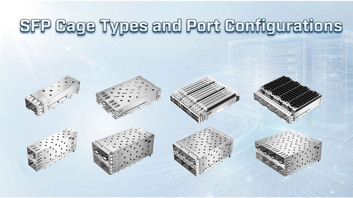
SFP Cage Port Configurations: 1x1, 1x2, 1x4, and Multi-Port Designs
SFP cage port configurations describe how many transceiver openings are arranged horizontally and vertically. The first number generally represents the number of port rows, while the second represents the number of ports per row.
Common configurations include:
|
Port Configuration |
Number of Ports |
Arrangement |
Typical Application |
|---|---|---|---|
|
1x1 |
1 |
Single row, single port |
Compact network devices |
|
1x2 |
2 |
One horizontal row |
Two-port switches |
|
1x4 |
4 |
One horizontal row |
High-density switches |
|
2x1 |
2 |
Two vertically stacked ports |
Compact front panels |
|
2x2 |
4 |
Two rows, two ports per row |
Enterprise switches |
|
2x4 |
8 |
Two rows, four ports per row |
High-density networking equipment |
Each configuration offers different mechanical and layout advantages.
-
1x1 SFP cage: Suitable for individual transceiver interfaces and applications requiring flexible port placement.
-
1x2 SFP cage: Provides two horizontally arranged ports with a relatively simple PCB layout.
-
1x4 SFP cage: Supports four ports in a single row and is useful for high-density front-panel designs.
-
2x1 SFP cage: Places two ports vertically, helping reduce horizontal front-panel space.
-
2x2 SFP cage: Combines four ports in a compact stacked arrangement.
-
2x4 SFP cage: Supports eight ports in a two-row arrangement for equipment requiring higher port density.
Port density should not be the only selection consideration. Multi-port cages also affect PCB routing, airflow, heatsink placement, and the mechanical clearance required for transceiver insertion.
Solder-Tail vs. Press-Fit SFP Cage Mounting
Solder-tail and press-fit are two common methods of attaching SFP cages to host PCBs. The main difference is how the mounting pins establish their mechanical and electrical connections with the board.
The following comparison explains their characteristics.
|
Parameter |
Solder-Tail Mounting |
Press-Fit Mounting |
|---|---|---|
|
PCB connection |
Soldered through-hole |
Interference-fit connection |
|
Assembly process |
Requires soldering |
Requires controlled insertion |
|
PCB preparation |
Plated through-holes and pads as specified |
Precisely dimensioned plated holes |
|
Mechanical retention |
Solder joints |
Mechanical interference |
|
Process control |
Solder temperature and joint quality |
Hole tolerance and insertion force |
|
Main consideration |
Solderability and joint reliability |
Hole dimensions and pin deformation |
Solder-tail mounting
Solder-tail SFP cages use metal pins that extend through the PCB and are secured by soldering.
Their characteristics include:
-
Established through-hole assembly processes.
-
Mechanical attachment through solder joints.
-
Compatibility with conventional PCB manufacturing workflows.
-
Requirements for appropriate solder-pad and hole dimensions.
Press-fit mounting
Press-fit SFP cages use specially designed compliant or interference-fit pins that establish a mechanical and electrical connection without conventional soldering at the mounting interface.
Their advantages include:
-
No soldering operation for the press-fit mounting pins.
-
Suitability for controlled high-volume assembly.
-
Reduced exposure to soldering-related thermal processes.
-
Consistent mechanical retention when PCB hole tolerances are maintained.
Neither mounting method is universally better. The appropriate choice depends on PCB construction, assembly equipment, production requirements, and the cage manufacturer's specifications.
SFP Cage Designs With Heatsinks and Light Pipes
SFP cages can incorporate additional thermal and optical features to support equipment integration. Heatsinks and light pipes are two common options, particularly in networking equipment with high port density.
SFP cages with heatsinks
Heatsinks help dissipate heat generated by installed transceivers.
Common characteristics include:
-
Integrated or separately attached heatsinks.
-
Increased heat-transfer surface area.
-
Compatibility with designated transceiver power and thermal requirements.
-
Additional vertical clearance requirements.
They are particularly relevant when multiple high-power modules operate in a compact enclosure.
SFP cages with light pipes
Light pipes transfer status indicators from LEDs on the PCB or connector assembly to the equipment's front panel.
Their functions include:
-
Displaying link status.
-
Indicating network activity.
-
Providing visual fault or diagnostic information.
-
Supporting front-panel status monitoring.
Some multi-port cage assemblies include outer and inner light pipes to support independent status indication for vertically arranged ports.
When selecting these designs, engineers should verify light-pipe positioning, LED alignment, front-panel clearance, and heatsink dimensions. These additional features must be considered as part of the complete mechanical assembly rather than as isolated accessories.
How to Choose the Right SFP Cage for Your Application
Choosing the right SFP cage requires matching the mechanical interface, electrical connector, PCB mounting structure, and environmental requirements of the host device.
A cage that physically resembles the original component may still be unsuitable if its mounting coordinates, internal dimensions, or EMI features differ.
The following selection process helps engineers evaluate compatibility before PCB fabrication or hardware assembly.
Determine the Required SFP Form Factor and Port Density
The first step is identifying the transceiver form factor and the number of ports required by the host device.
Consider the following factors:
-
Form factor: Determine whether the design uses SFP, SFP+, or SFP28 modules.
-
Data rate: Confirm the electrical interface requirements associated with the intended application.
-
Port quantity: Establish the number of transceiver interfaces required.
-
Port arrangement: Select a 1x1, 1x2, 1x4, 2x1, 2x2, or 2x4 configuration.
-
Front-panel dimensions: Check the available width, height, and insertion clearance.
-
PCB space: Evaluate the available board area and component placement.
For example, a compact enterprise switch may use 2x1 or 2x2 cage assemblies to increase front-panel port density. A device requiring independent port placement may benefit from individual 1x1 cages.
The selected configuration should also accommodate future hardware expansion and the intended airflow path.
Verify Pin Configuration and PCB Mounting Compatibility
PCB compatibility is one of the most important factors in SFP cage selection. The cage mounting pins and electrical connector must match the host board's mechanical and electrical design.
Before finalizing a component, verify:
-
The SFP connector contact arrangement and electrical interface.
-
Cage mounting pin locations and spacing.
-
Solder-tail or press-fit mounting requirements.
-
PCB hole diameters and plating specifications.
-
PCB thickness and recommended tolerances.
-
Connector alignment and module insertion depth.
-
Grounding pad and via locations.
It is important to distinguish between connector pinout compatibility and cage footprint compatibility.
A cage may use the correct 20-contact SFP connector but still fail to fit an existing PCB because its mounting pin positions or external dimensions differ.
Therefore, engineers should compare the complete mechanical drawings rather than relying on the connector type or product name alone.
Evaluate EMI Shielding and Thermal Requirements
EMI shielding and thermal management directly affect the reliability of an SFP cage assembly, particularly in high-density networking equipment.
The selection process should evaluate two areas.
EMI shielding requirements
Check the following features:
-
Internal and external EMI springs.
-
Conductive contact surfaces.
-
Cage grounding connections.
-
Cage material and surface plating.
-
Contact continuity with the host chassis.
-
Front-panel shielding arrangements.
A properly designed cage helps control electromagnetic emissions and maintain shielding continuity around the transceiver interface.
Thermal management requirements
Evaluate:
-
Maximum transceiver power dissipation.
-
Number of simultaneously operating ports.
-
Ambient operating temperature.
-
Available airflow and ventilation.
-
Heatsink compatibility.
-
Clearance between adjacent modules and heatsinks.
A single-port cage and an eight-port cage may have very different thermal requirements because the number of operating transceivers and the available airflow differ.
For higher-power applications, thermal testing under representative operating conditions is recommended before finalizing the mechanical design.
Check Mechanical Drawings and Manufacturing Specifications
Mechanical drawings and manufacturing specifications provide the most reliable basis for confirming whether an SFP cage is suitable for a particular host design.
Engineers should review the following documentation:
-
2D mechanical drawings with dimensions and tolerances.
-
3D CAD models for mechanical integration.
-
PCB footprint recommendations.
-
Mounting pin and hole specifications.
-
Cage material and plating information.
-
Operating temperature range.
-
EMI shielding specifications.
-
Light-pipe and heatsink dimensions, where applicable.
It is also important to verify the revision of the product drawing. A similar model number or product family does not automatically guarantee an identical footprint.
Before committing to PCB fabrication, a mechanical design review can identify potential problems involving panel alignment, module insertion, connector positioning, and adjacent component interference.
Common SFP Cage Selection and Installation Issues
SFP cage installation problems often result from incorrect mechanical dimensions, incompatible PCB footprints, inadequate grounding, or insufficient thermal clearance.
Most of these issues can be prevented by checking the manufacturer's drawings and validating the complete cage assembly before production.
ncorrect Cage Pin Spacing and PCB Footprint Mismatch
Incorrect mounting pin spacing is a common reason an SFP cage cannot be installed properly on an existing PCB.
Typical causes include:
-
Incorrect mounting-hole coordinates.
-
Different pin spacing between cage models.
-
Incorrect plated through-hole diameters.
-
Incompatible PCB thickness.
-
Differences between solder-tail and press-fit mounting structures.
These problems can lead to:
-
Misaligned cage assemblies.
-
Excessive press-fit insertion force.
-
Weak mechanical retention.
-
Damaged mounting pins.
-
Poor solder-joint quality.
To prevent these issues, follow a systematic verification process:
-
Obtain the exact mechanical drawing for the cage model.
-
Compare the mounting pin coordinates with the PCB footprint.
-
Check hole diameters and plating specifications.
-
Confirm the board thickness and dimensional tolerances.
-
Validate the assembly using a PCB prototype or mechanical inspection.
Do not modify the PCB footprint based solely on visual similarities between two cage models.
Poor EMI Shielding and Grounding Connections
Poor EMI performance can occur when the SFP cage does not establish reliable electrical contact with the PCB ground structure or equipment chassis.
Common causes include:
-
Damaged or deformed EMI springs.
-
Inadequate grounding connections.
-
Poor solder joints on cage mounting pins.
-
Incorrect cage positioning.
-
Incompatible front-panel grounding structures.
-
Contamination or oxidation on conductive contact surfaces.
Engineers can investigate these issues by:
-
Inspecting the cage and EMI contact fingers.
-
Checking the continuity of designated grounding paths.
-
Verifying mounting pin connections.
-
Inspecting solder joints and PCB grounding structures.
-
Confirming that the cage maintains proper contact with the chassis.
EMI performance should be validated through appropriate electromagnetic compatibility testing rather than relying only on visual inspection.
Thermal Problems and Insufficient Heatsink Clearance
Thermal problems can occur when SFP cages are installed too close together or when the equipment does not provide sufficient airflow.
Common contributing factors include:
-
High transceiver power consumption.
-
High port density.
-
Restricted ventilation openings.
-
Insufficient heatsink clearance.
-
Poor airflow through the equipment enclosure.
-
Elevated ambient temperature.
Possible solutions include:
-
Selecting a cage with a suitable heatsink configuration.
-
Improving airflow around the transceiver area.
-
Reviewing port spacing and thermal zoning.
-
Checking the temperature limits of the installed transceivers.
-
Performing thermal measurements under maximum expected operating load.
A cage with an integrated heatsink should not be selected without checking its mechanical clearance and thermal compatibility with the host enclosure.
Mechanical Interference and Transceiver Insertion Problems
Mechanical interference occurs when the cage, transceiver, connector, or front-panel structure does not align correctly.
Common symptoms include:
-
Difficulty inserting or removing the transceiver.
-
Improper latch engagement.
-
Module movement after installation.
-
Misalignment with the front-panel opening.
-
Physical contact with adjacent components.
-
Insufficient clearance for the extraction mechanism.
A practical troubleshooting approach includes:
-
Inspecting the internal cage dimensions.
-
Checking the transceiver package against the SFP MSA mechanical drawing.
-
Verifying the latch and retention mechanism.
-
Confirming connector alignment and insertion depth.
-
Reviewing front-panel and PCB component clearances.
If mechanical interference persists, compare the complete cage and transceiver drawings to identify the dimensional mismatch instead of applying excessive insertion force.
LINK-PP SFP Cage and Product Selection Guide
LINK-PP offers different SFP and SFP+ cage configurations for networking hardware manufacturers, including single-port, stacked, and multi-port assemblies. These products support different PCB mounting arrangements, EMI shielding requirements, and front-panel designs.
When evaluating LINK-PP SFP cages, engineers should compare port configuration, mounting type, mechanical dimensions, material, light-pipe options, and operating temperature.

Overview of LINK-PP SFP Cage Product Categories
LINK-PP SFP cage products cover multiple configurations designed for different networking equipment architectures.
The main product categories include:
-
1x1 SFP+ cages: Single-port assemblies for individual transceiver interfaces.
-
1x2 SFP+ cages: Two horizontally arranged ports for compact networking equipment.
-
1x4 SFP+ cages: Four horizontally arranged ports for high-density front panels.
-
2x1 SFP+ cages: Two vertically stacked ports for space-efficient layouts.
-
2x2 SFP+ cages: Four ports arranged in two rows.
-
2x4 SFP+ cages: Eight ports arranged in two rows for high-density applications.
Depending on the model, LINK-PP SFP cage assemblies can include:
-
Integrated electrical connectors.
-
Through-hole press-fit mounting.
-
Internal or external EMI springs.
-
Outer and inner light pipes.
-
Copper alloy cage construction.
-
Different plating and operating temperature specifications.
The availability of these configurations allows hardware designers to select cage assemblies according to their PCB layout and mechanical requirements.
Representative LINK-PP SFP Cage and Specifications
LINK-PP provides several SFP cage with different port arrangements and mounting structures. The following examples illustrate the differences between representative products.
|
LINK-PP Model |
Port Configuration |
Mounting Type |
Key Features |
|---|---|---|---|
|
LP11BC01000 |
1x1 |
Through-hole press-fit |
EMI spring, no light pipe |
|
LP21BC01101 |
2x1 |
Through-hole press-fit |
Outer/inner light pipes, external EMI springs |
|
LP22BC01001 |
2x2 |
Through-hole press-fit |
Four ports, nickel-plated copper alloy |
|
LP24BC01101 |
2x4 |
Press-fit |
Eight-port configuration, inner/outer light pipes |
The following product characteristics provide additional reference points for component selection.
1. LP11BC01000 – 1x1 SFP+ Cage
-
Single-port SFP+ cage.
-
Through-hole press-fit mounting.
-
EMI spring shielding.
-
Copper alloy with nickel plating.
-
Operating temperature: -55~+85°C.
-
No integrated light pipe.
This model is suitable for single-port SFP+ interfaces where a compact cage structure is required.
2. LP21BC01101 – 2x1 SFP+ Cage Connector
-
Two vertically arranged SFP+ ports.
-
Integrated electrical connector.
-
Through-hole press-fit mounting.
-
Outer and inner light pipes.
-
External EMI springs.
-
Copper alloy construction with 30µin plating.
-
Operating temperature: -40~+85°C.
-
Overall dimensions: 63.25mm × 14.00mm × 25.53mm.
The model is designed for stacked two-port applications and provides front-panel LED indication through integrated light pipes.
3. LP22BC01001 – 2x2 SFP+ Cage Connector
-
Four-port SFP+ cage assembly.
-
Two-row, two-column configuration.
-
Through-hole press-fit mounting.
-
Right-angle PCB mounting.
-
Nickel-plated copper alloy construction.
-
Material thickness: 0.25mm.
-
Operating temperature: -40~+85°C.
-
Overall dimensions: 63.25mm × 29.00mm × 25.53mm.
This model is suitable for four-port networking interfaces requiring a compact stacked configuration.
4. LP24BC01101 – 2x4 SFP+ Cage
-
Eight-port configuration.
-
Two-row, four-port arrangement.
-
Press-fit mounting structure.
-
Inner and outer light-pipe design.
This configuration is intended for networking equipment requiring higher SFP+ port density. Engineers should consult its product drawing for exact dimensions and mounting specifications.
These models demonstrate how LINK-PP SFP cage assemblies differ in port density, mechanical construction, and optional features. For final component selection, always refer to the corresponding product datasheet and mechanical drawing instead of assuming that models within the same product family share an identical PCB footprint.
How to Select a Suitable LINK-PP SFP Cage Model
Selecting a suitable LINK-PP SFP cage requires matching the product's mechanical and electrical characteristics with the host PCB design.
A practical selection process includes the following steps:
Step 1: Identify the port configuration
-
Select 1x1 for individual SFP+ interfaces.
-
Select 2x1 for two vertically stacked ports.
-
Select 2x2 for four ports in a two-row arrangement.
-
Select 2x4 for eight-port high-density designs.
Step 2: Verify the mounting method
-
Confirm whether the PCB requires through-hole press-fit mounting.
-
Check mounting pin dimensions and coordinates.
-
Verify PCB thickness and hole specifications.
-
Ensure that the cage assembly matches the existing PCB footprint.
Step 3: Evaluate optional features
-
Determine whether integrated light pipes are required.
-
Check internal and external EMI spring configurations.
-
Evaluate heatsink requirements.
-
Confirm ventilation and mechanical clearance.
Step 4: Check environmental specifications
-
Verify the operating temperature range.
-
Review cage material and plating.
-
Evaluate mechanical durability and EMI shielding requirements.
-
Confirm suitability for the intended equipment environment.
Step 5: Review product documentation
-
Obtain the corresponding 2D mechanical drawing.
-
Check the PCB mounting recommendations.
-
Review the product specifications.
-
Compare the selected cage with the existing host PCB design.
A model should only be considered mechanically compatible after its dimensional specifications and mounting structure have been verified.
LINK-PP SFP Cage Applications and Engineering Support
LINK-PP SFP cage assemblies can be considered for different networking hardware designs where standardized pluggable interfaces are required.
Typical application areas include:
-
Ethernet switches: Single-port and multi-port SFP cage configurations for access, aggregation, and core networking equipment.
-
Enterprise routers: SFP and SFP+ interfaces for fiber connectivity.
-
Network interface cards: Pluggable transceiver interfaces for server and network connectivity.
-
Data center equipment: High-density cage assemblies for compact networking platforms.
-
Telecommunications hardware: SFP cage structures for optical communication equipment.
-
Industrial networking devices: Cage configurations designed for applicable industrial temperature and mechanical requirements.
For engineers developing new hardware or replacing an existing cage assembly, product documentation is an important part of the selection process.
LINK-PP provides product drawings and technical specifications to support mechanical evaluation. Its technical support also covers product selection and compatibility verification.
Before finalizing a model, engineers should provide the existing part number, PCB footprint, required port arrangement, and mechanical drawing where available. This information helps narrow down suitable cage configurations and reduces the risk of selecting an incompatible component.
Conclusion
Selecting the right SFP cage requires more than checking its external dimensions. Engineers must understand SFP cage pins, the 20-pin electrical connector, transceiver package dimensions, PCB footprints, mounting methods, and EMI shielding requirements.
A suitable SFP cage should meet the host device's mechanical interface, electrical connection, thermal design, and manufacturing requirements.
The most important selection considerations are:
-
Pin compatibility: Distinguish cage mounting pins from the SFP 20-pin electrical connector.
-
Package dimensions: Verify transceiver dimensions, cage internal clearance, and external mechanical specifications.
-
PCB footprint: Match mounting pin spacing, hole dimensions, board thickness, and connector positioning.
-
Mounting method: Choose between solder-tail and press-fit configurations according to the PCB assembly process.
-
EMI and thermal performance: Evaluate grounding structures, shielding springs, airflow, and heatsink requirements.
-
Product selection: Compare LINK-PP SFP cage based on port configuration, mounting structure, dimensions, and optional features.
For networking hardware manufacturers and engineers, LINK-PP offers a range of SFP cage and connector solutions for different PCB layouts and port-density requirements.
Explore the LINK-PP Official Store to review available SFP cage, access technical drawings, and request a compatibility check and quotation. Standard in-stock products are eligible for a 15-day no-reason return and exchange policy, subject to applicable terms. For confirmed quality-related issues, LINK-PP covers the return shipping costs in accordance with its after-sales policy.
Choosing the correct SFP cage at the design stage helps reduce PCB integration risks, simplify hardware assembly, and support reliable long-term networking equipment operation.