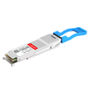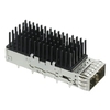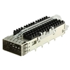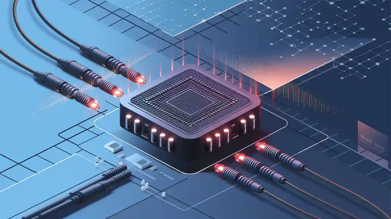
In modern high-speed networking, the need for greater bandwidth and higher port density has driven the rapid adoption of advanced interconnect solutions. The QSFP connector (Quad Small Form-factor Pluggable) stands out as a key enabler of this evolution, supporting data rates from 40G to 400G within a compact and scalable design. Widely used in data centers, telecommunications, and cloud infrastructure, QSFP connectors provide the performance and flexibility required to meet today’s growing data demands.
As networks transition toward higher speeds and more complex architectures, the QSFP connector has evolved to accommodate increasing bandwidth while maintaining compatibility and efficiency. Its ability to support multiple lanes, various transmission media, and standardized interfaces makes it a cornerstone of modern connectivity.
☀️ What is A QSFP Connector
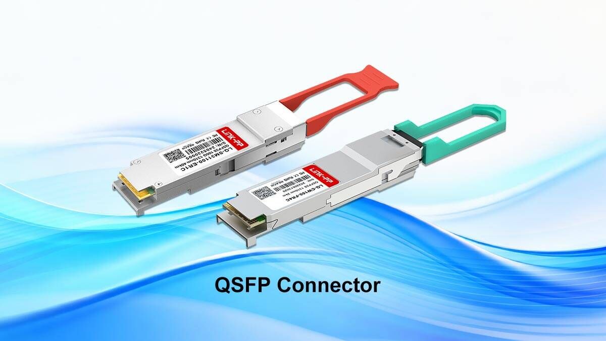
A QSFP connector is a high-speed, hot-pluggable module standard that enables data transmission through four parallel lanes within a compact module design. It bridges high-density data connections between networking hardware such as switches, routers, and servers, providing scalability from 40Gbps up to 400Gbps and beyond. In essence, the QSFP connector defines how modern networks achieve both speed and efficiency at scale.
Definition and Purpose of QSFP
The QSFP connector is defined as a hot-pluggable transceiver that combines four independent transmit and receive channels into a single module. Each channel can carry high-speed data, allowing the connector to aggregate bandwidth efficiently and achieve higher overall data rates. This multi-lane design is the foundation for its widespread use in 40G, 100G, 200G, and 400G applications.
Its primary purpose is to provide a standardized, high-density interface for fast data communication between network devices. By enabling hot-swappable modules, QSFP connectors simplify system upgrades and maintenance, reducing downtime while improving operational flexibility in large-scale network deployments.
History and Evolution from SFP to QSFP
The evolution of the QSFP connector began with the earlier SFP (Small Form-factor Pluggable) standard, which supported lower data rates such as 1G, 2.5G, and 4G. As network demands increased, SFP+ extended capabilities to 10G, but the need for even higher bandwidth led to the development of QSFP, which introduced a four-lane architecture to multiply data throughput.
Over time, QSFP technology has continued to evolve, giving rise to multiple module types such as QSFP+, QSFP28, QSFP56, and QSFP-DD. Each generation increases per-lane speed and overall bandwidth, enabling the transition from 40G to 400G while maintaining backward compatibility and consistent form factors for easier integration.
Key Physical and Electrical Characteristics
Physically, QSFP connectors are compact and rectangular, designed to fit high-density port configurations on networking equipment. They typically feature a 38-pin electrical interface and a standardized latch mechanism for secure insertion and removal. Their small footprint allows system designers to maximize port density without sacrificing performance.
Electrically, QSFP connectors support multiple high-speed differential signal lanes, usually four or more, depending on the variant. These lanes operate at high frequencies and require careful signal integrity management, including impedance control and low crosstalk. Advanced versions also incorporate power management and digital diagnostics to monitor performance in real time.
Standards that Define QSFP Connectors
QSFP connectors are governed by Multi-Source Agreements (MSAs), which establish electrical, mechanical, and optical interfaces to ensure interoperability across vendors. These standards specify parameters such as pin assignments, power limits, and optical wavelength compatibility, allowing different transceiver brands to function interchangeably within compliant systems.
Key governing standards include IEEE Ethernet specifications (40GBASE-LR4, 100GBASE-SR4, etc.), InfiniBand protocols for high-performance computing, and OIF (Optical Internetworking Forum) guidelines for signal integrity. Compliance with these standards ensures that QSFP solutions can meet the demanding requirements of modern data networks while avoiding vendor lock-in and compatibility issues.
☀️ How QSFP Connector Technology Works
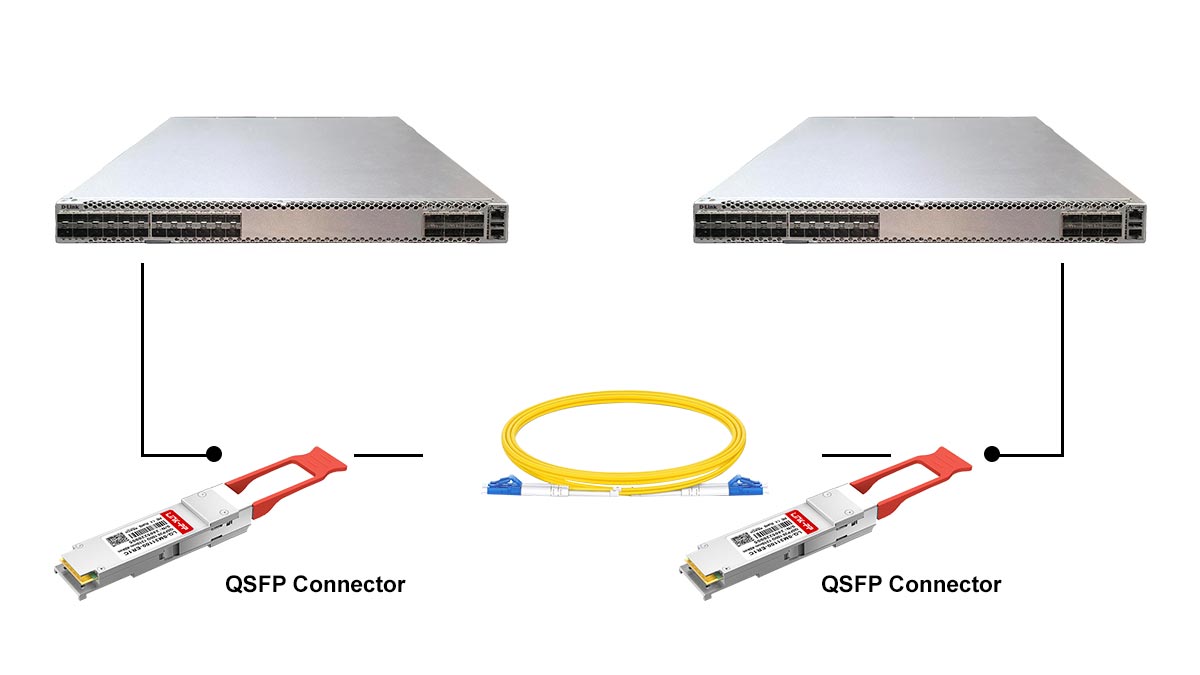
A QSFP connector serves as the physical and electrical gateway that enables high-speed optical communication between network devices. It manages the conversion, transmission, and reception of optical signals across multiple lanes, ensuring data flows efficiently through modern high-bandwidth environments. Understanding its internal architecture reveals how QSFP technology achieves exceptional density, scalability, and signal integrity in data center and telecom networks.
Basic Operating Principle of QSFP Modules
QSFP transceiver modules operate using parallel optical transmission, where each connector integrates four transmit and four receive channels. Every channel carries an independent optical signal on a dedicated wavelength, allowing data to be transferred simultaneously across all lanes. Depending on the module generation, each lane supports rates of 10G, 25G, 50G, or even 100G — enabling total throughput up to 400Gbps.
Core operational processes include:
- Electrical-to-Optical Conversion: Inside the transmitter, electrical input signals are converted into optical ones using laser diodes, typically VCSELs (Vertical Cavity Surface Emitting Lasers) or DFB (Distributed Feedback) lasers.
- Optical-to-Electrical Conversion: On the receiving side, photodiodes capture incoming light and convert it back into electrical signals for further processing.
Data Transmission Paths and Signaling Methods
Data transmission within a QSFP connector is achieved through differential signaling, where the data is transmitted across optical fibers using light pulses. Each lane in a QSFP module uses one optical fiber, ensuring that data flows independently and in parallel across the lanes. This parallelism maximizes the overall bandwidth of the module and allows for higher data throughput.
The signaling methods used in QSFP modules are typically based on advanced modulation techniques, such as PAM-4 (Pulse Amplitude Modulation with 4 levels), which is used to increase the data rate per lane. Unlike simpler methods such as NRZ (Non-Return to Zero), PAM-4 encodes two bits of data per signal, effectively doubling the potential data rate of each lane. This is especially crucial for higher-speed modules like QSFP28 and QSFP56, which aim to achieve 100G, 200G, and even 400G data rates by leveraging PAM-4 for efficient signal representation and transmission.
How Encoding and Modulation Affect Performance
Encoding and modulation play vital roles in the performance of QSFP connectors, especially as data speeds increase. PAM-4 is one of the key encoding schemes used in modern QSFP connectors, allowing for higher data rates by utilizing four distinct voltage levels instead of just two. This enables more data to be transmitted within the same time frame, effectively increasing the throughput without requiring additional physical lanes or bandwidth.
Modulation methods, such as QAM (Quadrature Amplitude Modulation), are also employed in high-speed QSFP modules to further optimize the signal and improve its ability to carry data efficiently. These modulation techniques adjust the amplitude and phase of the light signal to encode more information per transmission cycle. By utilizing both advanced encoding and modulation techniques, QSFP connectors are able to meet the high-performance and speed demands required by modern networks, ensuring reliable and efficient data transfer over long distances.
☀️ Common Types of QSFP Connector
QSFP connectors come in several generations, each designed to support higher bandwidth, denser port configurations, and more advanced signaling. The most widely used types include QSFP+, QSFP28, QSFP56, and QSFP-DD, while OSFP is another major type developed for very high-speed networking. Although these formats serve similar market needs, they differ in lane speed, electrical design, and upgrade path.
Understanding these types helps network designers choose the right QSFP connector for a specific speed target and infrastructure requirement. The sections below compare the most common QSFP variants and explain how QSFP-DD differs from OSFP in real deployment scenarios.
QSFP+, QSFP28, and QSFP56 Comparison
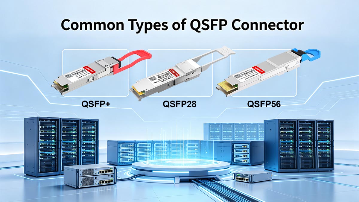
QSFP+ is the earlier mainstream version of the QSFP family and is commonly associated with 40G Ethernet. QSFP28 extends the same general form factor to 100G, while QSFP56 pushes performance to 200G by increasing the per-lane signaling rate. These three generations are often viewed as the natural progression of QSFP-based networking.
The table below summarizes the main differences among these three types.
| Connector Type |
QSFP+ |
QSFP28 |
QSFP56 |
| Max Data Rate |
40G |
100G |
200G |
| Transmission Speed per Lane |
10G |
25G |
50G |
| Common Use Cases |
Data Center Interconnects, 40G Ethernet |
High-Performance Computing, 100G Ethernet |
Telecom Networks, 200G Ethernet |
| Signaling Technology |
NRZ |
PAM-4 |
PAM-4 |
Differences between QSFP-DD and OSFP
QSFP-DD stands for Quad Small Form-factor Pluggable Double Density and is built to support 400G speeds by doubling the electrical lane count compared with earlier QSFP versions. It keeps a compact QSFP-style footprint while adding an 8-lane electrical interface, which makes it attractive for dense data center deployments. In practice, QSFP-DD is often chosen when backward compatibility and port density are priorities.
OSFP is a separate high-speed connector type designed with 400G and future higher-rate systems in mind. Compared with QSFP-DD, OSFP is generally larger and is optimized for thermal performance and next-generation power needs, while QSFP-DD emphasizes compatibility with the established QSFP ecosystem. The table below highlights the key distinctions.
| Connector Type |
QSFP-DD |
OSFP |
| Typical Data Rate |
400G |
400G and beyond |
| Lane Speed |
8 |
8 |
| Electrical Lanes |
50G |
50G |
| Design Focus |
Backward Compatibility and High Port Density |
Thermal Headroom and Forward-Looking Scalability |
☀️ QSFP Connector Pinouts and Form Factors
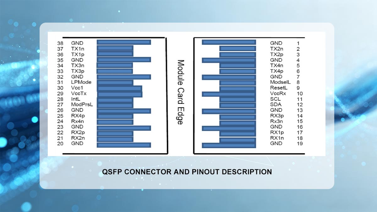
The design of QSFP connectors includes carefully defined pinouts and form factors that ensure high-density, reliable connections in modern networking environments. Pinouts refer to the specific arrangement of electrical pins within the connector that determines how signals are transmitted, while form factors define the physical size, shape, and layout of the connector. Both of these aspects are crucial for ensuring compatibility and efficient integration into network systems.
Understanding the layout and pinout specifications is essential for system integration, as well as for maintaining signal integrity and optimizing performance.
Overview of QSFP Interface Layout
The QSFP interface is designed to fit into high-density networking equipment such as switches, routers, and servers. Typically, the connector features a rectangular shape with a specific arrangement of pins that correspond to the various data lanes and power connections. Most QSFP connectors support four lanes, each carrying a high-speed signal, although newer standards like QSFP-DD support additional lanes for even higher data rates.
The connector layout also includes additional pins for power, ground, and management functions. These pins are crucial for powering the module and ensuring proper communication between the module and the host system. The QSFP interface is designed to be backward compatible with older QSFP standards, making it easier for manufacturers and users to upgrade their systems without significant redesigns.
Pin Definitions and Signal Mapping
The pinout of a QSFP connector is defined by its specific standard and use case, but it generally follows a consistent layout across different types of modules. In a typical QSFP module, the 38-pin arrangement includes pins dedicated to the four data lanes, as well as control, monitoring, and power connections.
For example, in a QSFP+ connector, the pins are organized as follows:
- Data Lanes: Pins 1-4 are used for the high-speed data transmission channels.
- Power Pins: Pins 5 and 6 provide the necessary power to the module.
- Ground Pins: Several pins are dedicated to grounding the module to ensure proper signal integrity and minimize noise.
- Control Pins: Additional pins are used for functions such as hot-plug detection and module identification.
Below is a simplified pinout diagram for a standard QSFP connector:
| Pin Number |
Function |
Description |
| 1-4 |
Data Lanes |
High-speed data transmission channels (e.g., 10G, 25G, 50G per lane) |
| 5-6 |
Power |
Provides the necessary power to the module |
| 7-10 |
Ground |
Used for grounding to reduce noise and improve signal integrity |
| 11-13 |
Control |
Includes functions like hot-plug detection and module management |
| 14-16 |
Diagnostic |
Used for monitoring module status and performance (e.g., temperature, voltage) |
This pinout structure ensures that the QSFP module operates reliably by clearly defining the roles of each pin in the connector.
Thermal and Mechanical Design Considerations
Thermal management is a key factor in the design of QSFP connectors, as the high-speed signals passing through the connectors can generate significant heat. Proper thermal design ensures that the connector and its associated module remain within safe operating temperatures, preventing overheating and performance degradation. As such, QSFP connectors are often equipped with heat sinks or thermal pads to dissipate heat effectively.
The mechanical design of QSFP connectors also includes considerations such as the locking mechanism, which ensures a secure connection and prevents accidental disconnections. Additionally, the form factor needs to be compatible with high-density configurations, as space is often limited in networking equipment. The connector must be designed to withstand frequent insertions and removals, ensuring durability over the lifespan of the module.
How Form Factor Impacts System Integration
The form factor of the QSFP connector plays a crucial role in determining how the module integrates into the overall system architecture. The size and shape of the connector influence how many ports can be accommodated on a given device, which in turn affects the overall density and scalability of the network.
As the demand for higher speeds and more ports increases, the form factor of connectors like QSFP-DD (Double Density) has evolved to provide more lanes without significantly increasing the space required. This allows manufacturers to build high-density switches and routers that can support 400G speeds while maintaining a compact form factor.
☀️ QSFP Connector Performance and Data Rates
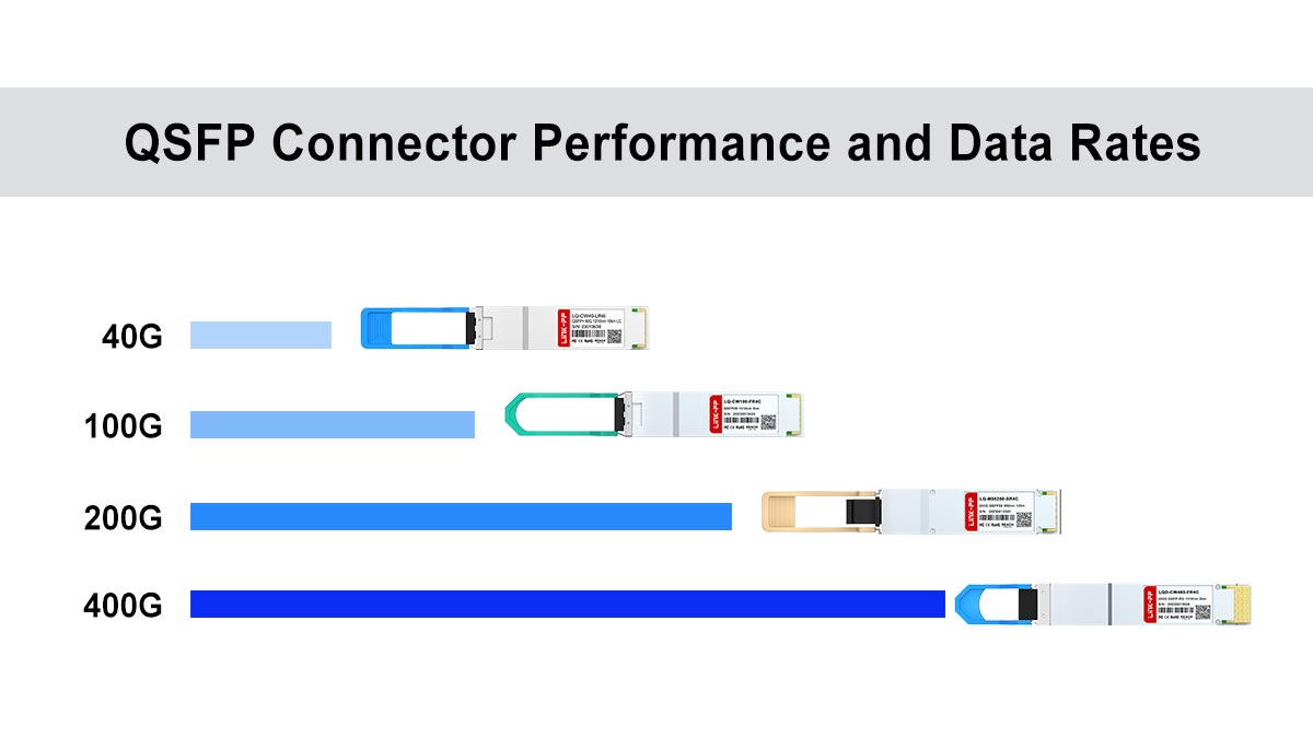
QSFP connector performance is mainly defined by how much data each lane can carry, how many lanes are active, and how well the module preserves signal quality at high speed. As the QSFP family has evolved, it has moved from 40G and 100G systems to 200G and 400G deployments.
In practice, performance is shaped by lane design, modulation method, power budget, and validation standards. The sections below explain the most important factors that determine real-world QSFP data rates and reliability.
Supported Data Rates (40G, 100G, 200G, 400G)
QSFP connectors have grown through several speed generations, each one increasing total bandwidth while preserving a compact form factor. QSFP+ is commonly associated with 40G, QSFP28 with 100G, QSFP56 with 200G, and QSFP-DD with 400G. These rate steps reflect the industry’s shift toward higher-capacity links in data centers and telecom networks.
The progression of supported speeds can be summarized as follows:
- 40G: Commonly delivered through QSFP+ and four-lane architectures.
- 100G: Typically associated with QSFP28 using four 25G lanes.
- 200G: Common in QSFP56 and some QSFP-DD configurations.
- 400G: A major target for QSFP-DD using eight lanes and higher per-lane signaling.
This scaling lets operators upgrade bandwidth without changing the entire network architecture.
Channel Density and Signal Integrity Challenges
Higher channel density allows more data to move through a smaller front-panel area, which is one of the main reasons QSFP remains so widely used. QSFP-DD, for example, doubles the electrical lane count relative to earlier QSFP generations, enabling much higher aggregate throughput in the same general footprint. That density is valuable, but it also makes the electrical design more demanding.
The main challenges are:
- Crosstalk: Closely packed lanes can interfere with one another.
- Loss and attenuation: High-speed signals weaken more quickly over imperfect paths.
- Jitter: Timing variation can reduce data accuracy.
- Signal-to-Noise Ratio: Faster links are more sensitive to noise and distortion.
For this reason, high-speed QSFP designs require careful routing, clean power delivery, and strict compliance testing.
Power Consumption Factors
Power consumption rises as data rates and lane counts increase, because the module must process more information at higher speeds. QSFP28 modules are generally lower power than QSFP-DD modules, while QSFP-DD may require significantly more power to support 400G operation and advanced signaling. This makes thermal management an important part of system planning.
Key factors that influence power use include:
- Lane Count: More lanes usually mean more active circuitry.
- Modulation Type: PAM4 typically requires more complex processing than NRZ.
- Reach Class: Longer optical reaches can increase transmitter and receiver demands.
- Host Platform Design: The cage, airflow, and power delivery affect module efficiency.
Because of this, designers must balance performance goals with thermal and energy constraints.
Testing and Validation Standards
QSFP connectors are not judged by raw speed alone; they must also pass testing that verifies electrical, optical, and mechanical reliability. Validation ensures that the module can operate at its rated data rate without excessive errors or instability. In high-speed networking, this step is essential because even small signal issues can affect large-scale systems.
Testing usually focuses on:
- Bit Error Rate: Measures how accurately the module transmits data.
- Signal Integrity: Checks whether lanes remain clean and stable.
- Power and Thermal Behavior: Confirms the module stays within operating limits.
- Standards Compliance: Verifies compatibility with the relevant MSA and IEEE requirements.
These standards and tests help ensure that QSFP connectors perform consistently across different vendors and network environments.
☀️ QSFP Connector Applications in Modern Networks
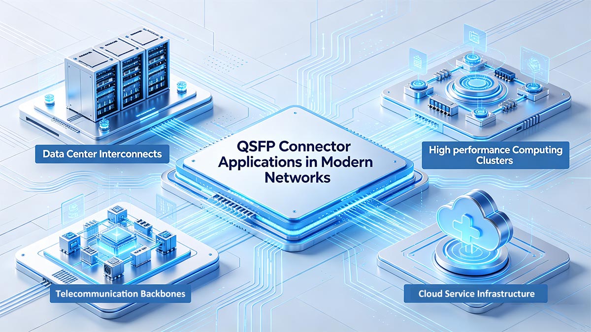
QSFP connectors are fundamental to modern high-speed network architectures, enabling scalable and reliable data transmission across various domains. Their ability to support ultra-high bandwidth and dense port configurations makes them indispensable in environments where performance and efficiency are critical. As network demands continue to grow, QSFP technology serves as a key enabler for next-generation infrastructure.
Data Center Interconnects
In data centers, QSFP connectors are primarily used to establish high-speed optical links between switches, routers, and storage systems. They enable efficient data exchange across racks and between geographically separated facilities, supporting large-scale east-west traffic patterns. With high port density and support for advanced optical modules, QSFP connectors help optimize space utilization while delivering the bandwidth required for modern data center operations.
High-performance Computing Clusters
QSFP connectors are extensively deployed in high-performance computing (HPC) clusters to facilitate ultra-low latency and high-throughput communication between compute nodes. These environments, which power applications such as scientific modeling and AI workloads, depend on fast and synchronized data transfer. QSFP-based optical interconnects ensure reliable performance under heavy computational loads, enabling efficient parallel processing and minimizing communication bottlenecks.
Telecommunication Backbones
Within telecommunication backbone networks, QSFP connectors support high-capacity optical transmission across core and aggregation layers. They are integral to deploying high-speed Ethernet standards such as 100G, 200G, and 400G, allowing carriers to handle rapidly increasing data traffic. Their standardized design and robust performance characteristics make them well-suited for long-haul and metro network deployments where stability and scalability are essential.
Cloud Service Infrastructure
Cloud service infrastructure relies heavily on QSFP connectors to deliver flexible, high-speed connectivity across distributed systems. These connectors enable seamless communication between compute, storage, and networking components within large-scale cloud environments. By supporting high data rates and modular upgrades, QSFP solutions allow cloud providers to scale infrastructure efficiently while maintaining consistent performance for latency-sensitive applications.
☀️ Compatibility and Interoperability of QSFP Connector
Compatibility and interoperability are critical factors in ensuring seamless integration of QSFP connectors within diverse networking environments. As multi-vendor deployments become the norm, adherence to industry standards and flexible configuration options play a key role in maintaining system efficiency. Proper understanding of interoperability features helps reduce deployment risks and optimize long-term network scalability.
MSA Compliance and Vendor Lock-in Risks
MSA compliance is the starting point for QSFP interoperability because it defines the common mechanical, electrical, and management rules that different vendors are expected to follow. When a module adheres to the same MSA, it is more likely to function correctly across multiple host platforms, which helps reduce integration risk.
At the same time, MSA compliance does not always guarantee trouble-free deployment. Some network vendors add their own firmware checks, vendor identifiers, or qualification lists that can restrict third-party optics and create vendor lock-in. Key risks include:
- “Unsupported module” warnings in the host system.
- Disabled diagnostics or limited monitoring functions.
- Port shutdowns caused by vendor policy, not by hardware failure.
- Reduced flexibility when mixing equipment from different suppliers.
Breakout Cables – 4x10G, 4x25G, and 4x50G Modes
Breakout operation lets one high-speed QSFP port split into multiple lower-speed links, which is useful when a switch uplink must connect to several access devices. This is often used to improve port utilization and simplify network design without adding more hardware.
The exact breakout mode depends on the module generation and the target port speeds. Common examples include:
- 4x10G, often used with older 40G-class deployments.
- 4x25G, widely used in 100G environments.
- 4x50G, used in higher-speed QSFP-DD-based systems.
Not every QSFP connector supports every breakout mode, so the host port, module type, and remote device must all be checked together before deployment.
Backward Compatibility with Lower-Speed Ports
Many QSFP connectors are designed with backward compatibility in mind, allowing higher-speed ports to support lower-speed modules where applicable. For instance, a QSFP28 port may accept a QSFP+ module, enabling 40G operation in a 100G-capable interface.
This backward compatibility provides flexibility during network upgrades, allowing incremental transitions without requiring a complete hardware overhaul. However, compatibility is not always guaranteed and depends on both hardware design and firmware support.
Firmware and EEPROM Programming for Cross-Vendor Use
Firmware and EEPROM data play a major role in whether a QSFP module is accepted by a switch. The host reads identification information from the module during initialization, and that data can determine whether the port comes up normally or is blocked by vendor policy.
Cross-vendor use often depends on how the module is programmed. Important factors include:
- Vendor identity fields stored in EEPROM.
- Compliance information recognized by the host platform.
- Firmware behavior on the switch or router.
- Support for diagnostics, monitoring, and link negotiation.
In many cases, properly programmed EEPROM data can improve interoperability, but it should always be handled carefully to avoid incorrect identification or unstable behavior.
☀️ Choosing the Right QSFP Connector for Your Network
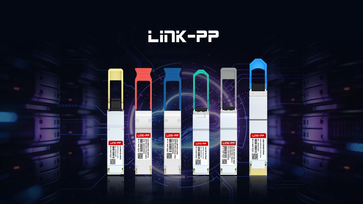
Choosing the right QSFP connector depends on three things: your required data rate, your target link distance, and the equipment standard your network already supports. In general, QSFP+ fits 40G environments, QSFP28 suits 100G deployments, QSFP56 serves higher-speed 200G links, and QSFP-DD is a stronger choice for dense 400G architectures.
Beyond speed, you should also consider compatibility, power budget, and thermal limits to avoid deployment issues later. If you are planning a new build or an upgrade path, choosing a module that matches both current needs and future scaling will save time and cost; for reliable sourcing and product selection, you can also explore the LINK-PP Official Store for QSFP solutions.