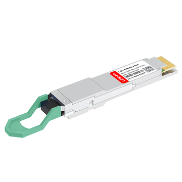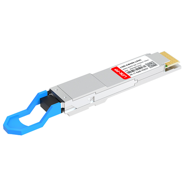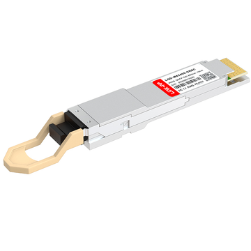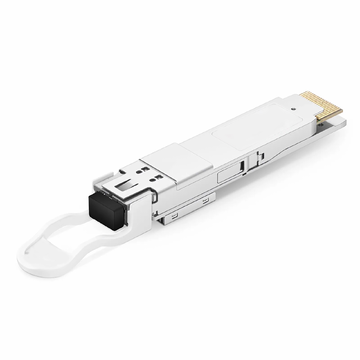
The rapid expansion of AI-driven computing and hyperscale cloud services has fundamentally changed the requirements for data center interconnects. To keep pace with this massive data influx, the industry has standardized the 400G QSFP56-DD as the primary form factor for high-speed, high-density networking.
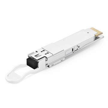
The 400G QSFP56-DD (Quad Small Form-factor Pluggable Double Density) is a high-density transceiver designed to provide 400 Gbps aggregate bandwidth. By utilizing an innovative 8-lane electrical interface and PAM4 modulation, this technology doubles the capacity of traditional QSFP modules without increasing their physical footprint on the switch faceplate.
For network architects and engineers, the QSFP-DD standard solves the critical challenge of scaling throughput while maintaining backward compatibility with legacy hardware. As data centers transition to 400G cores, understanding how the "Double Density" architecture handles signal integrity, thermal management, and various media types—from copper to long-reach fiber—is essential for building a reliable and scalable infrastructure.
🟨 What Is 400G QSFP56-DD? Understanding "Double Density"
The 400G QSFP56-DD is the dominant optical transceiver form factor used to achieve 400 Gbps Ethernet throughput. Defined by the QSFP-DD Multi-Source Agreement (MSA), this standard was developed to address the escalating bandwidth requirements of hyperscale data centers while maintaining a manageable power and thermal profile.

QSFP56-DD Meaning and Double-Density Design
To understand the "Double Density" designation, one must look at the physical interface of the module. While a standard QSFP28 or QSFP56 module uses a single row of electrical contacts (providing 4 lanes), the QSFP-DD adds a second row of gold fingers.
This architectural shift allows the module to support an 8-lane electrical interface. By doubling the number of lanes without significantly altering the width or height of the module, the "Double Density" design enables switch manufacturers to maintain the same port density on a 1U chassis—typically 32 or 36 ports—while quadrupling the total bandwidth compared to 100G systems.
QSFP56-DD Architecture and Design Standards
The architecture of the QSFP56-DD is grounded in the evolution of the 50G SerDes (Serializer/Deserializer) technology. The "56" in the nomenclature refers to the per-lane data rate of approximately 56 Gbps.
Key design specifications include:
-
Modulation: 4-level Pulse Amplitude Modulation (PAM4).
-
Electrical Interface: 8 lanes of 50G (PAM4), totaling 400 Gbps.
-
Physical Depth: The QSFP-DD module is slightly longer than a standard QSFP to accommodate the additional row of contacts and improved heat dissipation hardware.
-
Management Interface: Utilizes CMIS (Common Management Interface Specification) to provide robust diagnostic and control capabilities across multi-vendor platforms.
Why 8 Lanes Matter in 400G Networking
The transition from 4 lanes (used in 40G, 100G, and 200G) to 8 lanes is a critical inflection point for network efficiency. Historically, increasing speed meant increasing the baud rate per lane. However, as speeds reached 50G per lane, the signal integrity challenges of NRZ (Non-Return to Zero) became prohibitive.
By utilizing 8 lanes of 50G PAM4, the QSFP56-DD provides a reliable path to 400G without requiring experimental per-lane speeds that would exceed the capabilities of current PCB materials and silicon. Furthermore, this 8-lane configuration allows for versatile breakout options, such as splitting a single 400G port into 2x 200G or 8x 50G links, providing the granular flexibility required for diverse high-speed interconnects.
How 400G QSFP56-DD Fits Modern Data Center Architecture
In the context of modern leaf-spine and fabric architectures, the 400G QSFP56-DD serves as the primary interconnect for high-radix switches. It is specifically optimized for:
-
Spine-to-Leaf Links: Facilitating massive north-south traffic flows with reduced latency.
-
AI and Machine Learning Clusters: Providing the necessary fat-tree bandwidth required for GPU-to-GPU communication in distributed training workloads.
-
Aggregation Layers: Consolidating multiple 100G uplinks into a single 400G pipe, which simplifies cable management and reduces the number of physical ports required at the core.
By offering a high-density, low-latency, and power-efficient solution, the QSFP56-DD has become the foundational building block for the next generation of Ethernet fabrics.
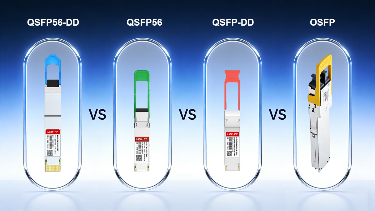
🟨 QSFP56-DD vs. QSFP56 vs. QSFP-DD vs. OSFP: What Is the Difference?
As data center speeds transitioned from 100G to 400G, a variety of nomenclature emerged that can be confusing for network planners. The distinctions between these standards lie in three primary areas: the number of electrical lanes, the modulation technique used per lane, and the physical mechanical dimensions of the module.
While all these form factors aim to increase bandwidth, they represent different stages of hardware evolution and offer varying trade-offs regarding thermal management and backward compatibility.
Comparison of High-Speed Transceiver Form Factors
| Feature | QSFP56 | QSFP56-DD | QSFP-DD (General) | OSFP |
| Maximum Bandwidth | 200 Gbps | 400 Gbps | 400G / 800G | 400G / 800G |
| Electrical Lanes | 4 Lanes | 8 Lanes | 8 Lanes | 8 Lanes |
| Modulation (Per Lane) | 50G PAM4 | 50G PAM4 | 50G or 112G PAM4 | 50G or 112G PAM4 |
| Backward Compatibility | Direct (QSFP+/QSFP28) | Direct (QSFP+/QSFP28/QSFP56) | Direct (QSFP series) | Requires Adapter |
| Thermal Capacity | Moderate (~5W) | High (12W–15W) | High (Up to 15W) | Very High (Up to 18W+) |
| Physical Dimensions | Standard QSFP | Standard (Double Row) | Standard (Double Row) | Slightly Larger / Wider |
Note on QSFP-DD vs. QSFP56-DD: In practical application, QSFP-DD is the physical mechanical specification (the "shell"), while QSFP56-DD refers specifically to the 400G implementation using 50G-56G PAM4 signaling per lane. As the industry scales, the same QSFP-DD shell is used for 800G (QSFP112-DD) by upgrading the lane speed to 112G.
QSFP56 vs. QSFP56-DD: Distinguishing 200G and 400G Form Factors
The most frequent point of confusion is the relationship between QSFP56 and QSFP56-DD. Although the "56" in both names refers to the use of 50G-56G PAM4 signaling, the throughput and architecture differ significantly:
-
QSFP56 (200G): This is a 4-lane solution. By applying PAM4 modulation to four 50G lanes, it achieves an aggregate throughput of 200 Gbps. It maintains the same physical connector layout as earlier QSFP modules (like QSFP28).
-
QSFP56-DD (400G): As the "Double Density" version, it utilizes 8 lanes of 50G PAM4. By doubling the lane count within a modified mechanical housing that features two rows of electrical contacts, it reaches 400 Gbps.
In short, QSFP56 is a 200G standard, whereas QSFP56-DD is a 400G standard. While a QSFP56-DD port can typically accept a QSFP56 module, the reverse is not possible due to the physical limitations of the legacy 4-lane interface.
The Nuance of QSFP-DD vs. QSFP56-DD
In technical documentation, "QSFP-DD" is often used interchangeably with "QSFP56-DD," but there is a subtle distinction. QSFP-DD refers to the mechanical form factor and the multi-source agreement (MSA) defining the 8-lane "Double Density" interface. QSFP56-DD refers specifically to the 400G implementation using 56G per-lane PAM4 signaling.
As the industry moves toward 800G, we now see QSFP112-DD, which uses the same QSFP-DD form factor but upgrades the lane speed to 112G. Therefore, QSFP-DD is the "envelope," and QSFP56-DD is the specific "400G contents" of that envelope.
QSFP-DD vs. OSFP: The Battle for High-Density Superiority
Parallel to the development of QSFP-DD is the OSFP (Octal Small Form-factor Pluggable). Both support 8-lane electrical interfaces and 400G/800G speeds, but they differ in design philosophy:
-
Form Factor Size: OSFP is slightly wider and deeper than QSFP-DD.
-
Thermal Performance: Because OSFP is larger and often includes integrated heat sinks, it can handle higher power loads (up to 15W–18W or more), which is advantageous for long-reach coherent optics (400G ZR/ZR+).
-
Backward Compatibility: QSFP-DD is natively backward compatible with legacy QSFP modules (QSFP28/QSFP+). OSFP requires a mechanical adapter to support QSFP modules, which adds complexity to the physical layer.
For most enterprise and commercial data centers, QSFP56-DD is the preferred 400G choice due to its seamless integration with existing QSFP infrastructure. OSFP is more commonly found in hyperscale environments (like Google or Arista-heavy deployments) where thermal headroom for future 800G and 1.6T speeds is the primary concern.
🟨 Backward Compatibility: Future-Proofing Your 400G Infrastructure
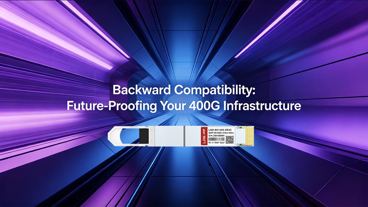
One of the most critical factors in the widespread adoption of the 400G QSFP56-DD standard is its native backward compatibility. Unlike competing standards that require entirely new physical interfaces, the QSFP-DD Multi-Source Agreement (MSA) prioritized a design that protects the massive investments organizations have already made in their fiber infrastructure and legacy optical modules.
For network architects, this means the transition to 400G does not necessitate a "rip-and-replace" approach for existing links. Instead, it allows for a phased migration where legacy and next-generation speeds coexist within the same high-density chassis.
Integrating Legacy QSFP Modules in 400G Ports
The mechanical design of the QSFP-DD port is "plug-compatible" with the entire family of QSFP transceivers. Because the QSFP-DD connector utilizes a two-row contact system, it can recognize and interface with older modules by using only the first row of electrical contacts.
This integration supports several legacy standards:
-
40G QSFP+: Direct insertion into a 400G port (utilizing 4 lanes of 10G NRZ).
-
100G QSFP28: Direct insertion (utilizing 4 lanes of 25G NRZ).
-
200G QSFP56: Direct insertion (utilizing 4 lanes of 50G PAM4).
When a legacy module, such as a 100G QSFP28, is inserted into a 400G QSFP-DD slot, the switch sense the module type and automatically disables the second row of electrical lanes. This allows the port to operate in "legacy mode," providing 100G throughput without the need for external adapters or specialized cabling.
The Strategic Value of Backward Compatibility
This backward-compatible architecture offers three distinct strategic advantages for modern data centers:
-
CAPEX Preservation: Organizations can purchase 400G-capable switches for their core and spine layers today while continuing to use their existing 100G transceivers for leaf-to-server or distribution links. This spreads out the cost of upgrading optics over a longer period.
-
Simplified Spares Management: By standardizing on QSFP-DD ports, data centers only need to manage one type of physical port throughout the fabric. This uniformity reduces the complexity of hardware inventory and troubleshooting.
-
Seamless Interoperability: Backward compatibility ensures that a 400G-enabled spine switch can communicate with an older 100G leaf switch using standard QSFP28 cables. This interoperability is vital for maintaining uptime during multi-stage infrastructure refreshes.
Technical Considerations for Backward Integration
While the mechanical fit is seamless, network engineers must account for the Electrical Signaling and Forward Error Correction (FEC) differences.
-
NRZ vs. PAM4: Legacy 100G (QSFP28) uses NRZ modulation, whereas 400G (QSFP56-DD) uses PAM4. The switch's SerDes (Serializer/Deserializer) must be capable of auto-negotiating between these two modulation types to ensure successful link-up.
-
FEC Interoperability: Modern 400G links rely on mandatory RS-FEC (Forward Error Correction). When connecting a 400G port to a 100G port, engineers must ensure that the FEC settings on both ends are aligned (e.g., disabling FEC or using the specific KR4/KP4 FEC required by the legacy module).
By addressing these technical nuances, the 400G QSFP56-DD provides a highly flexible, future-proofed pathway that bridges the gap between today’s 100G networks and the 800G/1.6T environments of the near future.
🟨 Managing Power Consumption and Heat in 400G Deployments
As data centers migrate to 400G, the thermal envelope of the optical transceiver has become a primary design constraint. The 400G QSFP56-DD provides significant bandwidth density, but this comes at the cost of increased power consumption per module. Managing the resulting heat is critical to maintaining signal integrity, laser longevity, and overall system reliability.
The Power Profile of 400G QSFP56-DD Modules
The power consumption of a 100G QSFP28 module typically ranges from 3.5W to 4.5W. In contrast, a 400G QSFP56-DD module consumes significantly more due to the integration of a high-performance Digital Signal Processor (DSP) required for PAM4 modulation and 8-lane electrical processing.
Current 400G power profiles generally fall into the following ranges:
-
SR8/DR4/FR4 (Short to Medium Reach): Typically 10W to 12W (typical module like Arista QDD-400G-SR8, Cisco QDD-400G-DR4-S, Dell 400GBASE-FR4).
-
LR4 (Long Reach): Approximately 12W to 13.5W (typical module like Dell 400GBASE-LR4).
-
ZR/ZR+ (Coherent/Ultra-Long Reach): Can reach 15W to 20W+ depending on the complexity of the DSP and optical amplification (typical module like Cisco QDD-400G-ZR-S and Cisco QDD-400G-ZRP-S).
According to the QSFP-DD Multi-Source Agreement (MSA), these modules are categorized into Power Classes (1 through 8). Network engineers must verify that the switch chassis and specific port cooling capabilities align with the power class of the transceiver being deployed.
Thermal Dissipation and Module Design
To handle these higher thermal loads, the QSFP56-DD specification includes specific mechanical enhancements. Many 400G modules utilize a "Type 2" mechanical design, which features an extended housing that protrudes further into the airflow path of the switch.
This extension often incorporates:
-
Integrated Heat Sinks: Built-in fins on the module surface to increase the surface area for convective cooling.
-
Optimized Thermal Interface Materials (TIM): High-conductivity materials inside the module to transfer heat from the DSP and laser diode to the external shell.
-
Riding Heat Sinks: Many high-radix switches use a "riding" heat sink design on the cage itself, which makes direct physical contact with the transceiver to pull heat away toward the system fans.
System-Level Airflow and Reliability
The density of 400G deployments—often 32 ports in a 1U switch—presents a cumulative thermal challenge. A fully populated switch can generate over 400 Watts of heat from the transceivers alone, excluding the power draw of the switching silicon (ASIC) and fans.
Proper thermal management requires:
-
Airflow Directionality: Ensuring the switch airflow (Front-to-Back or Back-to-Front) matches the data center’s hot/cold aisle containment strategy.
-
Monitoring via CMIS: Utilizing the Common Management Interface Specification (CMIS) to monitor real-time temperature telemetry. If a module exceeds its operating temperature (typically 70°C for commercial grade), the switch may throttle performance or shut down the port to prevent permanent hardware damage.
-
Baud Rate and DSP Efficiency: Newer generations of 7nm and 5nm DSP silicon are significantly more power-efficient, reducing the "Watts per Gigabit" ratio. Selecting modules with the latest silicon generation is an effective way to lower the overall cooling requirements of the rack.
Failure to manage these thermal parameters can lead to an increased Bit Error Rate (BER) and a decrease in the Mean Time Between Failures (MTBF) for the optical components. Therefore, thermal analysis is now as fundamental to 400G network planning as link budget and distance calculations.
🟨 Which 400G QSFP56-DD Module Should You Choose?
Selecting the appropriate 400G QSFP56-DD module depends on three primary variables: the physical transmission distance, the type of fiber infrastructure (Multimode vs. Singlemode), and the requirement for "breakout" configurations. Each module type is optimized for specific layers of the data center fabric, from top-of-rack server connections to long-haul data center interconnects (DCI).
400G SR8 for Short-Reach Links
The 400G SR8 (Short Reach) is designed for intra-rack or rack-to-rack connectivity over Multimode Fiber (MMF).
-
Distance: Up to 100 meters over OM4 fiber.
-
Architecture: It utilizes 8 parallel lanes, each carrying 50G PAM4.
-
Connector Type: Typically requires an MPO-16 connector or a 24-fiber MPO to support the 8-lane parallel transmission.
The SR8 is often favored for its lower power consumption and transceiver cost. However, because it requires 16 fibers for a single link, the high cost of high-count MMF cabling often limits its use to short-distance "leaf-to-server" or "leaf-to-leaf" applications where cable management is manageable.
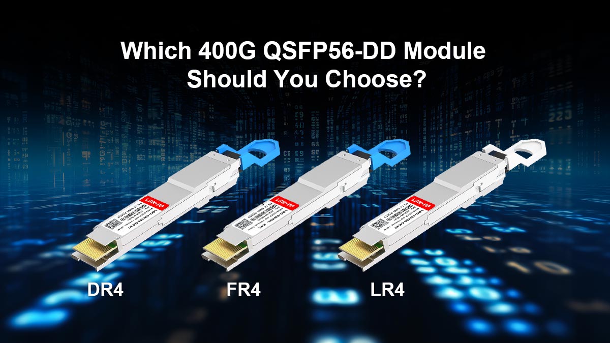
400G DR4, FR4, and LR4 Use Cases
For spans exceeding 100 meters, Singlemode Fiber (SMF) becomes the standard. These modules utilize different optical multiplexing techniques to optimize fiber usage:
-
400G DR4 (500m): The "Datacenter Reach" module uses 4 parallel SMF lanes. Each lane carries 100G (achieved by an internal gearbox converting 8x50G electrical to 4x100G optical). The DR4 is the primary choice for breakout applications, allowing a single 400G port to be split into four 100G (DR1) links. It uses an MPO-12 connector.
-
400G FR4 (2km): The "Fiber Reach" module uses CWDM4 (Coarse Wavelength Division Multiplexing) technology. It multiplexes four 100G wavelengths onto a single pair of LC-terminated fibers. This makes it highly cost-effective for "leaf-to-spine" links, as it significantly reduces the amount of fiber cabling required over 2km distances.
-
400G LR4 (10km): The "Long Reach" module is designed for campus-scale connectivity. It uses LAN-WDM multiplexing to ensure signal integrity over 10km. This is typically used to connect disparate data center halls or large-scale campus hubs.
400G ZR and ZR+ for Long-Reach Networks
The 400G ZR and ZR+ modules represent the most advanced tier of QSFP56-DD technology, introducing Coherent Optics into the pluggable form factor.
-
400G ZR: Designed for Data Center Interconnects (DCI) up to 80km–120km. It follows the OIF (Optical Interworking Forum) standards to ensure interoperability between different vendor platforms.
-
400G ZR+: An extended version that supports even longer distances and multi-rate configurations (100G/200G/300G/400G).
By utilizing 400G ZR/ZR+ modules, network operators can transmit 400G directly from a switch port over DWDM (Dense Wavelength Division Multiplexing) networks without the need for expensive, standalone transponder systems. This "IP over DWDM" approach drastically reduces both CAPEX and the physical footprint of long-haul networking equipment.
Summary of Reach and Application
| Module Type | Reach | Fiber Type | Connector | Primary Use Case |
| SR8 | 100m | MMF (OM4) | MPO-16 | Intra-rack / Short-range |
| DR4 | 500m | SMF | MPO-12 | 4x100G Breakout / Leaf-Spine |
| FR4 | 2km | SMF | LC Duplex | High-density Leaf-Spine |
| LR4 | 10km | SMF | LC Duplex | Campus Backbones |
| ZR/ZR+ | 80km+ | SMF | LC Duplex | Data Center Interconnect (DCI) |
🟨 FAQ About 400G QSFP56-DD
As the industry standardizes on 400G for high-performance networking, several technical questions frequently arise regarding form factors, hardware interoperability, and naming conventions. Below are the most common inquiries addressed from a technical deployment perspective.
1. What does QSFP-DD stand for?
QSFP-DD stands for Quad Small Form-factor Pluggable Double Density.
-
Quad: Refers to the original four-channel structure of the QSFP family.
-
Double Density: Refers to the doubling of the electrical lanes from 4 to 8. This is achieved by adding a second row of electrical contacts inside the connector, allowing the module to maintain a compact size while doubling its total bandwidth capacity.
2. What is the difference between QSFP-DD and QSFP56?
The primary difference lies in the number of electrical lanes and the resulting total throughput.
-
QSFP56 utilizes 4 lanes of 50G PAM4 to reach an aggregate of 200 Gbps. It uses a single row of contacts.
-
QSFP-DD (specifically QSFP56-DD) utilizes 8 lanes of 50G PAM4 to reach 400 Gbps. It uses a double row of contacts.
While both use the same 50G PAM4 signaling per lane, the QSFP-DD architecture is designed to support twice the volume of data by doubling the physical lane count.
3. Is QSFP-DD compatible with legacy QSFP modules?
Yes. One of the defining features of the QSFP-DD port is its mechanical backward compatibility. The cage is designed to accept older 4-lane modules such as 100G QSFP28 and 40G QSFP+. When a legacy module is inserted, the switch identifies that only the first row of contacts is engaged and operates the port in the corresponding legacy mode (e.g., 100G or 40G).
4. What is SFP56-DD, and is it related to 400G?
SFP56-DD is the "Double Density" version of the smaller SFP (Small Form-factor Pluggable) interface. While QSFP-DD targets 400G and 800G, SFP56-DD typically targets 100G (2 lanes of 50G PAM4). It is often used for high-density server-to-Top-of-Rack (ToR) connections where a full QSFP port is not required. It is a separate standard and is not physically interchangeable with 400G QSFP-DD ports.
5. Why do 400G modules get so hot?
The increased heat is primarily due to the Digital Signal Processor (DSP). Unlike 10G modules or 25G transceivers, 400G modules require a powerful DSP to handle PAM4 modulation, clock and data recovery (CDR), and Forward Error Correction (FEC). These processes are energy-intensive. A 400G QSFP56-DD module can draw between 10W and 15W, requiring advanced system-level cooling and integrated heat sinks on the module itself to ensure stable operation.
6. Can I breakout a 400G QSFP56-DD port?
Yes, this is one of the most common use cases in leaf-spine architectures. Depending on the transceiver type, you can use breakout cables to split a 400G port into:
-
4x 100G (using a DR4 module and an MPO-to-4xLC breakout cable).
-
2x 200G (using specific breakout configurations).
-
8x 50G (typically used in high-density server deployments).
This flexibility allows for high-radix switching, where a single high-speed port serves multiple lower-speed downstream devices.
🟨 Choosing Between 400G DAC, AOC, and Optical Transceivers: Final Considerations
The decision to deploy 400G QSFP56-DD depends heavily on the specific reach requirements and the thermal budget of the data center environment. As we look toward the future of high-density networking, the "Total Cost of Ownership" (TCO) is no longer calculated solely by the price of the module, but also by power efficiency and cabling complexity.
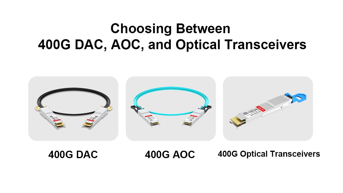
Direct Attach Copper (DAC): The Intra-Rack Standard
For short-range connections under 2.5 meters—typically from a Top-of-Rack (ToR) switch to a server—400G DACs remain the most cost-effective solution. They consume zero power and offer the lowest latency. However, at 400G speeds, copper cables have become significantly thicker and stiffer, leading to a rise in the adoption of Active Copper Cables (ACC). ACCs use a small linear amplifier to extend reach and reduce cable bulk, making them easier to manage in high-density racks.
Active Optical Cables (AOC): Flexibility for Inter-Rack Links
When distances exceed 3 meters but stay within 30 meters, 400G AOCs are the preferred choice. Because they use optical fiber instead of copper, they are significantly lighter and more flexible, which improves airflow within the cabinet. AOCs are frequently used for "End-of-Row" (EoR) or "Middle-of-Row" (MoR) architectures where switches and servers are not co-located in the same rack.
Optical Transceivers: The Core of the Fabric
For any distance beyond 30 meters, or for environments requiring structured cabling, independent Optical Transceivers (SR8, DR4, FR4) are necessary.
-
SR8 is ideal for short-reach multimode links.
-
DR4 and FR4 are the industry workhorses for leaf-to-spine connectivity over singlemode fiber, offering the best balance of reach (500m to 2km) and scalability.
Strategic Sourcing for 400G Deployments
Implementing a 400G infrastructure requires hardware that strictly adheres to the QSFP-DD MSA standards to ensure multi-vendor interoperability and thermal stability. Whether you are upgrading a legacy 100G environment or building an AI-ready fabric from scratch, the quality of the interconnect is the determining factor in network uptime.
For engineers and procurement teams seeking high-performance, MSA-compliant components, the LINK-PP Official Store provides a comprehensive portfolio of 400G QSFP56-DD solutions, including DACs, AOCs, and a full range of optical transceivers. Sourcing from a specialized manufacturer ensures that your deployment meets the rigorous signal integrity and power efficiency standards required by modern high-density data centers.