
In a world where everyone is talking about ultra-fast 40G or 100G speeds, the 1.25G SFP module might seem like an "old-school" tool. However, it is still the "hidden hero" of many networks today. Because it’s affordable and reliable, 1.25G is still the go-to choice for everyday tasks like connecting office switches, setting up home fiber, or linking devices where super-high bandwidth isn't necessary.
But here’s the tricky part: just because a 1.25G module fits into a switch doesn’t mean it will actually work. Different brands often use their own "languages," which can lead to frustrating connection issues. In this article, we’ll explain how to make sure your 1.25G SFP gear works perfectly across different switch brands and how to avoid the common "plug-and-play" headaches.
? What is a 1.25G SFP Module and Why It Still Matters
The 1.25G SFP module is a compact, hot-pluggable optical transceiver used widely in data communications and telecommunications to bridge the gap between networking hardware and fiber optic or copper cabling. Despite the industry’s shift toward 10GBASE, 25GBASE, 40GBASE, and 100GBASE speeds, the 1.25G SFP remains a cornerstone of networking due to its high reliability, low power consumption, and cost-effectiveness in diverse environments.
Definition and Basic Functionality
A 1.25G SFP is a standardized interface that converts electrical signals from a switch or router into optical or electrical signals for transmission over a network. These modules are designed according to the Multi-Source Agreement (MSA), which ensures that different manufacturers can produce hardware that is physically compatible with one another. By plugging into a fixed port, they allow for flexible network configuration, enabling users to change the transmission distance or fiber type without replacing the entire switch.
Operating primarily at the Gigabit Ethernet rate, these transceivers utilize different laser types and wavelengths to transmit data over varying distances. Whether using laser diodes for long-range fiber or integrated circuits for copper-based Cat5e cables, the core functionality remains the same: providing a modular, high-speed uplink that supports the foundational connectivity of modern digital infrastructure.
Common Use Cases in Legacy and Modern Networks
- Enterprise Access Layers: Many businesses still use 1.25G SFP for connecting end-user workstations, IP phones, and wireless access points to the main distribution switches.
- Industrial Automation: In manufacturing plants, 1.25G SFP transceivers are preferred for their stability and lower heat generation when connecting PLCs and industrial sensors.
- FTTH and Broadband Access: Internet Service Providers (ISPs) frequently use Gigabit SFP modules in Optical Line Terminals (OLTs) to provide high-speed residential fiber connections.
- Security and Surveillance: High-definition IP cameras often require a steady 1Gbps link, making 1.25G SFP modules the ideal choice for long-distance video backhaul in large facilities.
Why 1.25G Transceiver Remains Relevant Today
While high-bandwidth applications like data centers require 100G+ speeds, 1.25G SFP modules remain relevant because they provide sufficient bandwidth for the vast majority of standard office and industrial tasks at a fraction of the cost. The power envelope of a 1.25G module is significantly lower than that of 10G SFP+ modules, which reduces the overall cooling requirements and operational expenses of a network rack.
Furthermore, the longevity of 1.25G technology is sustained by the massive existing infrastructure of OM2/OM3 multi-mode and G.652 single-mode fiber. Many organizations find that upgrading to 10G requires expensive cabling overhauls, whereas sticking with 1.25G allows them to maintain their current fiber plant while still achieving the stable, low latency performance required for modern VoIP and cloud-based applications.
? 1.25G SFP Compatibility Across Switch Vendors
Achieving seamless interoperability across different hardware vendors is one of the most significant challenges when deploying 1.25G SFP modules. While the physical dimensions are standardized by the MSA, the internal software and communication protocols often vary, requiring a deeper understanding of how modules communicate with their host switches.
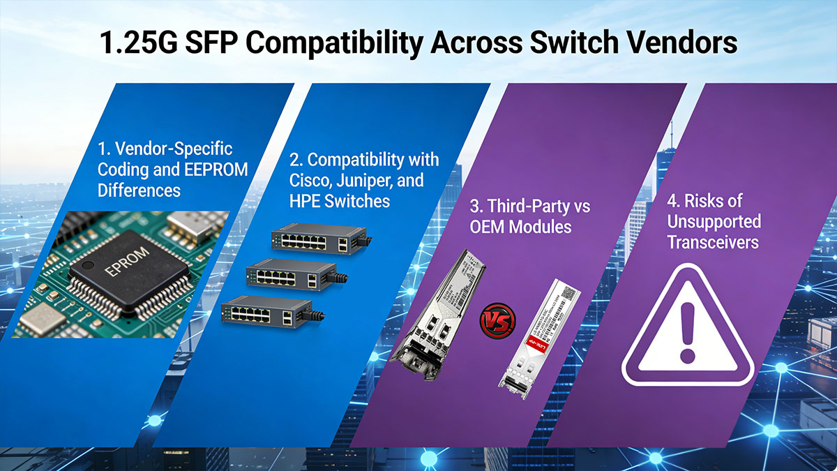
Vendor-Specific Coding and EEPROM Differences
Every SFP module contains an EEPROM (Electrically Erasable Programmable Read-Only Memory) chip that holds essential data, such as the manufacturer’s name, serial number, and product ID. Many major switch vendors implement "vendor locking," where the switch’s operating system checks this internal code before allowing the port to initialize. If the code does not match the required vendor data, the switch may disable the port or trigger a warning message.
This coding is not just about brand loyalty; it also includes specific parameters for Digital Optical Monitoring (DOM) and power levels tailored to the switch's hardware. Consequently, a module that works perfectly in a Cisco switch might be completely unrecognized by an HPE or Juniper device unless the EEPROM has been specifically programmed with the correct vendor-specific algorithms and checksums.
Compatibility with Cisco, Juniper, and HPE Switches
- Cisco: Known for strict compatibility checks, Cisco switches often require a "Cisco-coded" module. However, users can often bypass minor warnings using the service unsupported-transceiver command on certain IOS versions.
- Juniper: Generally more "open" than other brands, Juniper devices usually allow third-party modules to work, though they may lack full technical support or advanced DDM (Digital Diagnostic Monitoring) visibility if the coding is incorrect.
- HPE/Aruba: These vendors are particularly stringent, often requiring specific "J-number" matching. Using non-HPE coded modules in Aruba switches frequently results in a "Class 4" or "Unrecognized Transceiver" error, requiring precise third-party programming.
Third-Party vs OEM Modules
OEM 1.25G modules are transceivers sold directly by switch brands like Cisco or Juniper; they are guaranteed to work but often come with a massive price premium. In contrast, third-party compatible 1.25G modules are produced by specialized optical manufacturers. These modules offer the same performance and hardware quality as OEMs, but they are programmed with custom firmware to "mimic" the identity of an OEM module, allowing them to pass the switch's compatibility check.
The primary advantage of third-party compatible SFP modules is cost-efficiency, often saving organizations up to 70% on deployment costs. As long as the supplier uses high-quality components and verified coding databases, these modules provide the same level of reliability and performance as their expensive OEM counterparts without voiding the hardware warranty of the host switch.
Risks of Unsupported Transceivers
While third-party modules offer significant cost savings, using 1.25G transceivers that lack proper coding or verification can introduce a range of technical and administrative complications. These risks range from immediate hardware rejection to long-term maintenance difficulties that can compromise overall network reliability.
- Port Lockouts: The most common risk is the "err-disable" state, where the switch software detects an unauthorized module and shuts down the port entirely to protect the system.
- Missing Diagnostic Data: Unsupported modules may fail to provide real-time data on temperature, laser bias current, and optical power levels (DOM/DDM), making troubleshooting extremely difficult.
- System Instability: Poorly coded modules can occasionally cause high CPU usage on the switch or intermittent link flaps, leading to unpredictable network downtime.
- Warranty and Support Hurdles: If a network issue occurs, OEM technical support may refuse to troubleshoot the link until the third-party transceiver is replaced with an "official" one.
? Key Factors Affecting SFP 1.25G Interoperability
Successful 1.25G SFP deployment depends on more than just software coding; it requires a precise match between optical specifications, physical hardware, and switch firmware. If any of these variables are misaligned, the link will either fail to initialize or suffer from poor performance and data loss.
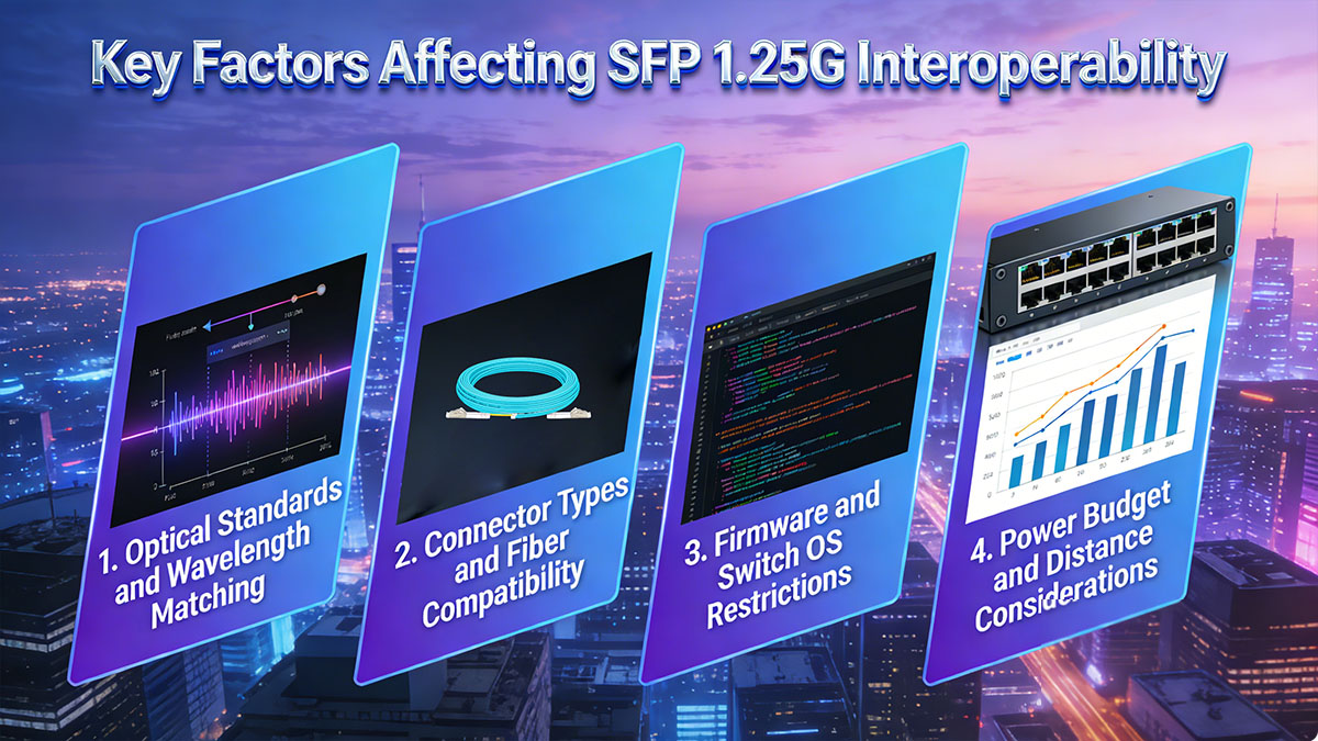
Optical Standards and Wavelength Matching
Optical interoperability is governed by the IEEE 802.3z standard, which ensures that transceivers can "speak" the same language over fiber. For a connection to be established, the transceivers at both ends of the fiber link must operate at the same wavelength and follow the same transmission protocol.
- 850nm (SX): Standard for short-range transmission over multi-mode fiber, typically reaching up to 550m.
- 1310nm (LX/LH): Used for intermediate distances, supporting both single-mode (up to 10km) and multi-mode fiber.
- 1550nm (ZX/EZX): Designed for long-haul applications, reaching distances of 80km to 120km over single-mode fiber.
Connector Types and Fiber Compatibility
The physical interface and the type of fiber optic cabling used are critical for signal integrity. While the SFP form factor is standardized, the internal optics must be paired with the correct fiber core diameter and connector polish to prevent excessive signal reflection or attenuation.
- Fiber Type: Multi-mode fiber (OM2/OM3) is required for SX modules, while single-mode fiber is necessary for LX, ZX, and EZX modules.
- Connector Interface: Most 1.25G SFP modules use the LC Duplex connector, but Copper SFPs use the RJ45 interface.
- Polish Type: Standard SFPs typically use UPC (Ultra Physical Contact) connectors. Connecting a UPC module to an APC (Angled Physical Contact) cable will result in high insertion loss and link failure.
Firmware and Switch OS Restrictions
The switch operating system acts as the primary gatekeeper for hardware compatibility, validating the SFP’s internal EEPROM data against its own firmware rules. Even if the optical specifications are a perfect match, the switch may refuse to enable the port if the transceiver's software profile does not satisfy the OS’s specific security or vendor-matching requirements.
- Vendor Whitelisting: Many firmware versions are programmed to recognize only specific vendor IDs; if the module is not on the "approved" list, the OS may disable the port or trigger an "unsupported" error.
- Speed Auto-negotiation Issues: In newer 10G SFP+ ports, the firmware may fail to automatically detect and down-speed to a 1.25G module, often requiring manual CLI commands to lock the port at 1000Mbps.
- OS Update Volatility: Firmware updates can introduce stricter validation protocols or updated encryption keys, which may cause previously functional third-party modules to become unrecognized after a system reboot.
Power Budget and Distance Considerations
Power budget refers to the amount of light available to maintain a stable link after accounting for distance and connection losses. Interoperability fails if the signal is either too weak to be detected or too strong for the receiver to handle.
Receiver Sensitivity: If the fiber run is too long or has too many splices, the signal strength drops below the receiver's threshold, leading to a "No Signal" error.
Optical Saturation: High-power long-distance modules (like GLC-ZX-SM-RGD) can "blind" or damage a short-range receiver. In these cases, optical attenuators must be used to reduce the signal to a safe level.
Link Loss Margin: A reliable setup should always account for a 2-3dB power margin to compensate for fiber aging, dust, or environmental temperature changes.
? 1.25G SFP Module Types and Their Compatibility Differences
1.25G SFP modules are categorized into several distinct types based on their transmission medium, wavelength, and environmental durability. Selecting the correct transceiver module is essential not only for physical connectivity but also to ensure that the transceiver's power consumption and thermal profile align with the host switch's hardware limits.
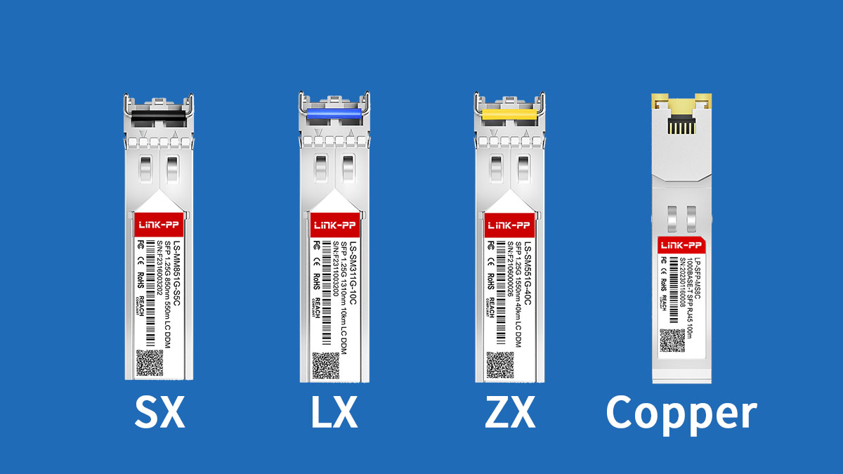
SX vs LX vs ZX SFP Modules
These module types are defined by the specific IEEE standards they follow, which dictate the wavelength and laser power required for different transmission distances. The primary technical variation lies in the optical engine: 1.25G SFP SX modules (like GLC-SX-MM-RGD) use short-wavelength 850nm VCSEL lasers for local data center links, while 1.25G SFP LX (like GLC-LX-SM-RGD) and 1.25G SFP ZX (like GLC-ZX-SM-RGD) modules utilize long-wavelength 1310nm or 1550nm lasers (FP or DFB) to achieve the signal integrity needed for campus or metropolitan-scale distances.
The following table highlights the specific technical differences and application ranges for these three common optical modules.
| Feature |
SX |
LX |
ZX |
| Wavelength |
850nm |
1310nm |
1550nm |
| Fiber Type |
Multimode Fiber |
Single-mode Fiber |
Single-mode Fiber |
| Max Distance |
550m |
10km -20km |
80km - 120km |
| Typical Use Case |
Intra-building / LAN |
Campus Backbones |
Long-haul Network Connection |
SX and LX Compatibility Nuances: While SX is strictly for multi-mode fiber, LX is unique because it can support both single-mode and multi-mode. However, when deploying an LX module on older OM1 or OM2 multi-mode fiber, a "mode-conditioning patch cable" is often required to prevent signal distortion caused by Differential Mode Delay (DMD).
ZX Power and Safety Risks: ZX modules are high-power optics designed to overcome high levels of signal attenuation over long distances. Because of their high launch power, they are often incompatible with short-range fiber runs; connecting two ZX modules over a short distance without an optical attenuator will likely saturate or permanently damage the sensitive optical receiver.
Optical vs Copper (RJ45) SFP Modules
The choice between fiber SFP and copper SFP is usually dictated by the existing cabling infrastructure and the required distance between networking devices. While both deliver 1.25G speeds, they differ significantly in their physical medium, power requirements, and susceptibility to environmental factors.
The comparison below outlines the fundamental differences between fiber-based and copper-based 1.25G SFP transceivers.
| Feature |
Fiber SFP |
Copper SFP |
| Medium |
Fiber Optic Cable |
Category 5/5e/6 Copper |
| Connector |
LC Duplex / Simplex |
RJ45 |
| Max Distance |
120km |
100m |
| Power Consumption |
Lower |
Higher |
Transmission and EMI Resistance: Fiber optic SFP module offers superior performance for high-speed data over long distances and are completely immune to electromagnetic interference (EMI). This makes them the preferred choice for industrial environments or for connecting switches across different floors where electrical isolation is required.
Heat and Density Concerns: SFP Copper transceivers provide a convenient way to add RJ45 ports to an SFP-only switch for short-run connections. However, they generate significantly more heat than optical modules; in high-density switch environments, filling every port with Copper SFP modules can lead to thermal throttling or power supply strain if the switch’s cooling system is not robust enough.
Single-Mode vs Multi-Mode SFP Modules
The fundamental difference between these two types lies in the core diameter of the fiber they support and the way light travels through that core. This distinction is the most common cause of "no link" issues during deployment if the fiber plant and transceivers are mismatched.
The table below summarizes the core characteristics and operational rules of 1.25G SFP single mode transceivers and multimode modules.
| Feature |
Multimode SFP |
Single-mode SFP |
| Core Diameter |
50µm or 62.5µm |
9µm |
| Typical Wavelength |
850nm |
1310nm or 1550nm |
| Light Source |
VCSEL Laser |
DFB Laser |
| Modal Dispersion |
High (limits distance) |
Negligible |
| Application |
LAN or short campus links |
Long-haul and metro links |
Light Propagation Differences: Multi-mode fiber allows light to travel in multiple paths (modes), which causes the signal to spread out (modal dispersion) over long distances, strictly limiting its reach to a few hundred meters. Single-mode fiber forces light into a single, direct path through a much narrower core, allowing for extreme precision and vastly longer distances without signal degradation.
Interoperability Rule: It is impossible to mix single-mode and multi-mode SFPs on the same link. Because the core diameters and wavelengths are physically incompatible, the light from a multi-mode SFP will not effectively enter a single-mode fiber, and vice versa, resulting in a complete failure to establish a link.
Industrial vs Commercial Grade SFP Modules
Beyond optical specifications, 1.25G SFP modules are categorized by their ability to withstand environmental stress, particularly extreme temperature fluctuations. This distinction is critical for deployments in unmanaged or outdoor environments.
Operating Temperature Ranges: Commercial-grade modules (COM) are designed for standard, climate-controlled indoor environments with an operating range of 0°C to 70°C. Industrial-grade modules (IND) are "hardened" to operate in extreme conditions ranging from -40°C to 85°C, making them essential for outdoor enclosures, factory floors, or traffic control systems.
Component Durability and Reliability: Industrial SFP modules are built with higher-grade internal components and specialized soldering to handle the physical expansion and contraction caused by rapid temperature changes. While a commercial module might work temporarily in a harsh environment, it will eventually suffer from "laser drift" or premature hardware failure, whereas industrial modules are specifically tested for long-term stability in unmanaged settings.
? How to Ensure 1.25G SFP Compatibility Before Deployment
Before deploying 1.25G SFP modules in your network infrastructures, it’s essential to verify their compatibility with the target switches and network infrastructure. A proactive approach — combining documentation review, lab testing, and technical validation — helps minimize connection failures and ensure smooth integration.
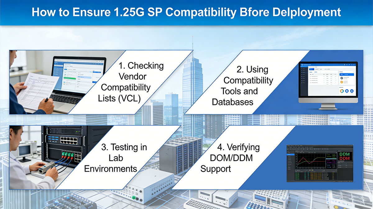
Checking Vendor Compatibility Lists (VCL)
Most switch manufacturers provide official compatibility lists specifying supported SFP models and firmware versions. Reviewing these lists ensures you choose modules designed and tested for your specific switch model, reducing the risk of link instability or recognition failures.
Using Compatibility Tools and Databases
Online compatibility databases and vendor-provided tools can quickly validate whether a third-party transceiver matches your switch’s specifications. These tools check EEPROM codes, optical parameters, and supported features, helping you identify potential mismatches before deployment.
Testing in Lab Environments
Running a test deployment in a controlled lab setup allows you to verify actual link performance, optical power levels, and interoperability with different hardware. This step helps uncover hidden incompatibilities that documentation alone might not reveal.
Verifying DOM/DDM Support
Digital Optical Monitoring (DOM) or Digital Diagnostic Monitoring (DDM) features provide real-time metrics like temperature, voltage, TX/RX power, and bias current. Ensuring that both the SFP and switch support these functions ensures transparent monitoring and reliable maintenance during live operation.
? Common Compatibility Issues with SFP 1.25G
Even with careful planning, compatibility issues can arise during the installation or operation of 1.25G SFP modules. These problems often stem from hidden software locks, physical environment mismatches, or incorrect configuration settings that prevent the link from achieving its full potential.
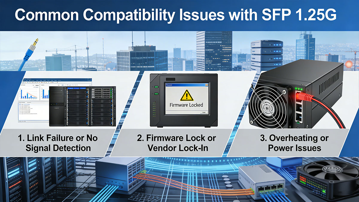
Link Failure or No Signal Detection
The most common issue is a "No Signal" or "Link Down" status, which typically points to a mismatch between the transceiver type and the fiber cabling. This often occurs when a multi-mode SFP is connected to single-mode fiber, or when the transmit and receive strands of a duplex fiber cable are swapped, known as a polarity issue. If the hardware is correct, a link failure might also be caused by a dirty optical connector or a laser that has shifted off its designated wavelength, requiring a thorough inspection and cleaning of all optical interfaces.
Mismatched Speed or Duplex Settings
Interoperability issues frequently occur when 1.25G SFP modules are inserted into 10G SFP+ ports that do not support auto-negotiation for lower speeds. If the port defaults to 10G or "auto" and fails to detect the 1G SFP module, the link will remain inactive until the speed is manually forced to 1000Mbps in the switch’s Command Line Interface (CLI). Additionally, ensuring that both ends of the link are set to the same duplex mode is critical, as a duplex mismatch can lead to excessive packet collisions and degraded network performance.
Firmware Lock or Vendor Lock-In
Many vendors use software-based locks to prevent the use of non-original transceivers, resulting in the switch placing the port into an "err-disable" or "unauthorized" state. This vendor lock-in is enforced via the switch’s operating system, which checks the module's EEPROM for a specific security key or recognized vendor ID. Resolving this often requires using modules that have been specifically programmed with compatible third-party firmware or, in some cases, entering hidden configuration commands like service unsupported-transceiver to allow the use of non-OEM hardware.
Overheating or Power Issues
Since 1.25G SFP modules draw power directly from the host switch, compatibility issues can arise if the module’s power consumption exceeds the port’s allocated budget. This is particularly common with Copper 1000BASE-T SFP modules, which generate significant heat and consume more electricity than optical versions. If a switch rack is poorly ventilated or if too many high-power modules are installed in adjacent ports, the resulting overheating can cause the transceiver's laser to drift or the switch port to shut down to prevent hardware damage.
? Choosing Reliable Suppliers for Compatible 1.25G SFP Modules
Selecting a supplier for 1.25G SFP modules requires looking beyond the initial price tag to ensure long-term network stability. A reliable partner provides transceivers that are not only physically robust but also expertly programmed to navigate the complex firmware requirements of modern switching platforms.
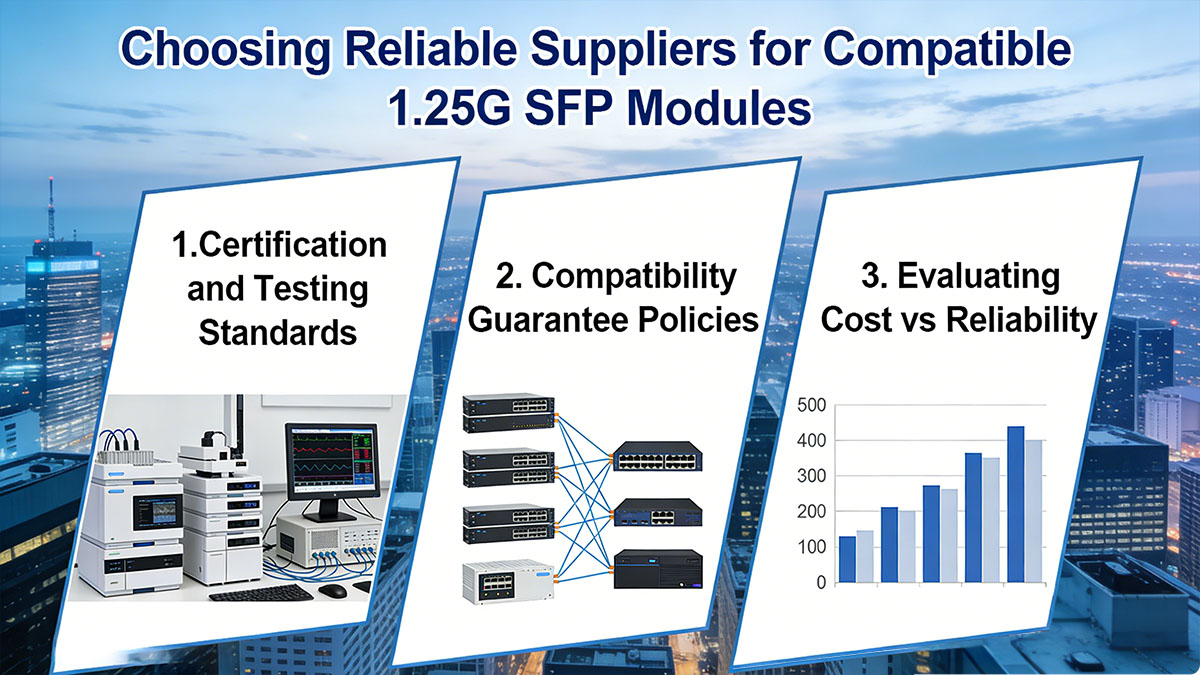
Certification and Testing Standards
Reputable suppliers adhere to strict international standards, including MSA (Multi-Source Agreement) compliance and ISO 9001 quality management systems, to ensure physical and electrical consistency. Beyond these certifications, the best suppliers perform "real-switch" testing, where modules are validated in actual hardware from vendors like Cisco, Juniper, and Dell rather than just being tested on generic simulators. This rigorous validation process ensures that the laser performance, signal-to-noise ratio, and data throughput meet or exceed the original equipment manufacturer (OEM) specifications.
Compatibility Guarantee Policies
A trustworthy supplier should offer a comprehensive compatibility guarantee, explicitly promising that their 1.25G SFP modules will function seamlessly within your specific networking environment. This policy usually includes dedicated technical support and a clear return or replacement program in the event of a firmware conflict or an "unsupported transceiver" error. Such guarantees are vital for enterprise deployments, as they shift the technical risk away from the network administrator and ensure that any interoperability hurdles are resolved quickly without additional costs.
Evaluating Cost vs Reliability
While third-party 1.25G SFP modules can offer up to 70% savings compared to OEM optics, the lowest price often indicates a compromise in component quality or testing depth. When evaluating suppliers, it is crucial to find the balance where significant cost reduction meets high reliability and low failure rates. Investing in high-quality third-party optics from a verified source prevents the hidden costs associated with network downtime, troubleshooting hours, and premature hardware failure, ultimately delivering a superior total cost of ownership (TCO).
? Conclusion: Best Practices for 1.25G SFP Module Interoperability
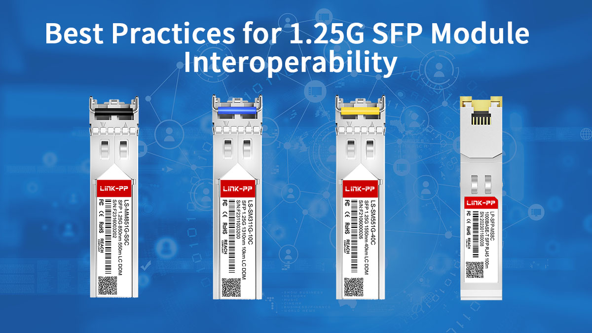
Achieving seamless interoperability with 1.25G SFP modules is a blend of technical precision and strategic sourcing. To ensure your network remains stable and efficient, always prioritize matching the correct optical standards — such as wavelength and fiber type — while verifying that the module’s internal coding is specifically tailored for your switch’s operating system. By utilizing tools like Digital Optical Monitoring (DOM) and conducting thorough lab testing before a full-scale rollout, you can proactively eliminate the most common causes of link failure and performance degradation.
As networking environments continue to evolve, the 1.25G SFP remains an indispensable tool for cost-effective, reliable connectivity. Whether you are maintaining a legacy system or building out a new enterprise access layer, the key to success lies in partnering with a supplier that understands the nuances of vendor-specific coding and hardware reliability. For high-performance, fully compatible optical solutions tailored to your infrastructure needs, explore the comprehensive range of 1.25G SFP transceivers available at the LINK-PP Official Store, where quality and interoperability are guaranteed for every deployment.


