
In Gigabit Ethernet networks, fiber resources are often limited, especially in access networks, campus infrastructures, and long-distance connections between distributed facilities. The 1000BASE-BX standard was developed to address this challenge by enabling bidirectional Gigabit Ethernet transmission over a single strand of single-mode fiber. Instead of using two fibers for transmit and receive paths, 1000BASE-BX relies on wavelength division multiplexing (WDM) to separate upstream and downstream optical signals, effectively doubling fiber utilization.
Defined within the IEEE 802.3 Ethernet standards—particularly through the Ethernet in the First Mile (EFM) specifications—1000BASE-BX allows two complementary optical transceivers to communicate simultaneously using different wavelengths on the same fiber. This design makes the technology particularly valuable in environments where deploying additional fiber infrastructure is costly or impractical.
Beyond its efficient fiber usage, 1000BASE-BX also incorporates the standard Gigabit Ethernet physical layer architecture, including the Physical Coding Sublayer (PCS), Physical Medium Attachment (PMA), and Physical Medium Dependent (PMD) components. Together, these PHY sublayers manage encoding, serialization, clock recovery, and optical signal transmission to ensure reliable data communication.
Understanding how WDM principles and PHY sublayer logic work together is essential for engineers designing or maintaining single-fiber Ethernet links. The following sections explore the technical structure of the 1000BASE-BX standard, including its optical transmission mechanism, PHY architecture, and practical deployment considerations.
?️? What Is the 1000BASE-BX Standard?
1000BASE-BX is a Gigabit Ethernet optical transmission standard designed to deliver 1Gbps communication over a single strand of single-mode fiber. Unlike traditional Gigabit fiber standards that require two fibers—one for transmitting and one for receiving—1000BASE-BX uses wavelength division multiplexing (WDM) to allow bidirectional data transmission on the same fiber. This approach significantly improves fiber utilization and is widely used in access networks, campus infrastructure, and environments where fiber availability is limited.
The standard maintains compatibility with the broader Gigabit Ethernet architecture while introducing a single-fiber optical transmission method. It defines both the optical signaling characteristics and the PHY layer behavior required for reliable communication.
Position of 1000BASE-BX in the IEEE 802.3 Family
1000BASE-BX is part of the Gigabit Ethernet optical family defined by IEEE 802.3 and is closely associated with the Ethernet in the First Mile (EFM) specifications introduced in IEEE 802.3ah. The goal of these specifications was to extend Ethernet technology into access networks while maintaining interoperability with existing Ethernet systems.
Within the 1000BASE-X group, different standards address different fiber types and link distances.
The table below summarizes how 1000BASE-BX fits within common Gigabit Ethernet optical standards.
The key distinction is that 1000BASE-BX achieves full-duplex Gigabit Ethernet communication using only one fiber, which can significantly reduce infrastructure requirements in large-scale network deployments.
Key Technical Specifications
The 1000BASE-BX standard defines several technical parameters that ensure reliable single-fiber Gigabit Ethernet transmission. These specifications cover data rate, optical wavelengths, fiber type compatibility, and link distance.
| Parameter |
Specification |
Description |
| Data Rate |
1Gbps |
Standard Gigabit Ethernet throughput |
| Fiber Type |
Single-mode fiber |
Typically OS1 or OS2 fiber |
| Transmission |
Bidirectional |
Simultaneous TX and RX on one fiber |
| Typical Distance |
up to 10km |
Defined by BX10 specification |
These characteristics make the technology suitable for metropolitan access networks, enterprise inter-building links, and telecom edge infrastructure where efficient fiber utilization is important.
1000BASE-BX Variants
The standard defines complementary transceiver types that operate in pairs. Each device uses a different transmit wavelength and receive wavelength so that two modules can communicate without signal collision on the same fiber.
Two primary variants are commonly deployed.
These two variants must be used together to establish a functioning link. One device transmits at 1490nm while receiving at 1310nm, and the other operates in the opposite direction.
Because the wavelengths are separated, WDM filters inside the optical transceiver can isolate the incoming and outgoing signals even though they travel through the same fiber. This design enables stable full-duplex communication while maintaining compatibility with standard Gigabit Ethernet PHY mechanisms.
?️? WDM Principles Behind 1000BASE-BX
The ability of 1000BASE-BX to transmit and receive data simultaneously over a single fiber relies on wavelength division multiplexing (WDM). Instead of separating traffic by physical fibers, the technology separates signals by optical wavelength. Each device sends data using one wavelength and receives data using another, allowing full-duplex communication through a single strand of fiber without signal interference.
In practice, WDM components inside the optical transceiver combine and separate these optical signals. This mechanism enables efficient fiber usage while maintaining stable Gigabit Ethernet performance.
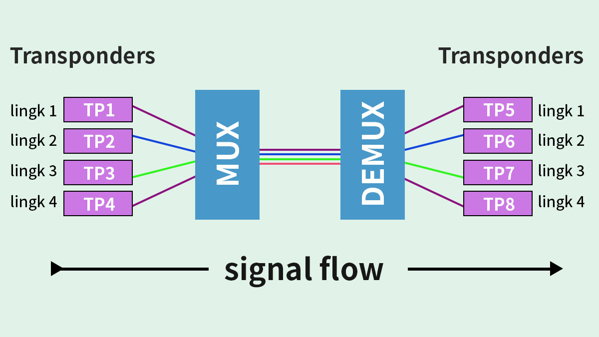
Basics of Wavelength Division Multiplexing
Wavelength division multiplexing is an optical transmission technique that allows multiple signals to travel through the same fiber by assigning each signal a different wavelength. Because optical wavelengths do not interfere with one another when properly filtered, they can coexist within the same fiber path.
In the case of 1000BASE-BX, WDM is used in a simple bidirectional form where one wavelength carries traffic in one direction and another wavelength carries traffic in the opposite direction.
| Concept |
Description |
Role in 1000BASE-BX |
| Optical wavelength |
Specific light frequency used for transmission |
Separates transmit and receive signals |
| Multiplexing |
Combining multiple wavelengths onto one fiber |
Enables single-fiber communication |
| Demultiplexing |
Separating wavelengths at the receiver |
Allows the device to detect incoming signals |
This approach differs from traditional dual-fiber Ethernet links, where transmit and receive paths are physically separated. By using optical wavelength separation instead, the BX standard reduces the number of fibers required for a link by half.
Wavelength Pairing in 1000BASE-BX Links
For a 1000BASE-BX connection to function correctly, the two optical modules on each end of the fiber must use complementary wavelength pairs. Each device transmits at one wavelength while receiving at another, ensuring that signals do not conflict.
The following table illustrates a typical wavelength pairing used in BX links.
| Module Type |
Transmit Wavelength |
Receive Wavelength |
| BX-D |
1490nm |
1310nm |
| BX-U |
1310nm |
1490nm |
Because the transmit wavelength of one module matches the receive wavelength of the other, the two devices form a matched pair capable of bidirectional communication.
When deploying BX links, network engineers must ensure that the correct module pair is used. Using two identical modules would result in both devices transmitting on the same wavelength, preventing the link from establishing.
Optical Components Enabling Single-Fiber Transmission
The single-fiber operation of 1000BASE-BX is made possible by integrating several optical components within the transceiver module. These components manage wavelength separation and ensure that transmitted and received signals remain isolated.
Key components typically include:
-
WDM filter
Separates incoming and outgoing wavelengths so that the receiver only detects the intended optical signal.
-
Laser transmitter
Generates the optical signal at the assigned wavelength, typically 1310nm or 1490nm.
-
Photodiode receiver
Converts the incoming optical signal into an electrical signal for further processing by the PHY.
-
Optical coupling elements
Direct transmitted and received light through the same fiber interface while maintaining signal separation.
Inside the module, the WDM filter acts as the central optical element. It directs the outgoing laser signal into the fiber while simultaneously routing incoming light of a different wavelength toward the receiver. This filtering process ensures that the transmitted signal does not overwhelm the receiver even though both signals share the same fiber path.
Through this combination of wavelength management and optical filtering, 1000BASE-BX achieves efficient full-duplex Gigabit Ethernet communication using a single fiber strand.
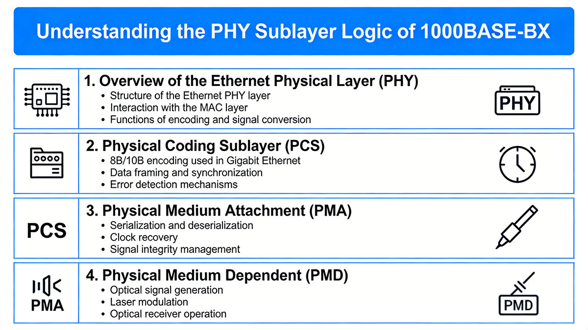
?️? Understanding the PHY Sublayer Logic of 1000BASE-BX
The 1000BASE-BX standard relies on the same physical layer architecture used in Gigabit Ethernet over fiber. While the optical transmission method differs due to the use of WDM and single-fiber communication, the internal PHY structure remains consistent with the 1000BASE-X framework defined in IEEE Ethernet standards.
The PHY layer is responsible for converting Ethernet data frames into physical signals that can be transmitted over the optical medium. In 1000BASE-BX systems, this process includes encoding digital data, serializing the bit stream, recovering timing information, and generating optical signals at specific wavelengths.
The PHY logic is typically divided into three functional sublayers: the Physical Coding Sublayer (PCS), the Physical Medium Attachment (PMA), and the Physical Medium Dependent (PMD) sublayer.
Overview of the Ethernet Physical Layer (PHY)
The Ethernet PHY acts as the bridge between the Media Access Control (MAC) layer and the physical transmission medium. Its primary purpose is to transform digital data into signals suitable for optical transport and to convert received optical signals back into digital data.
In Gigabit Ethernet optical systems, the PHY performs several key functions.
-
Data encoding and decoding
Converts Ethernet data frames into encoded bit streams for reliable transmission.
-
Clock synchronization
Maintains timing alignment between transmitting and receiving devices.
-
Signal serialization
Converts parallel data from the MAC layer into a high-speed serial stream.
-
Optical signal conversion
Generates and detects optical signals traveling through fiber.
These functions are distributed across the PCS, PMA, and PMD sublayers.
| PHY Sublayer |
Primary Function |
Role in Transmission |
| PCS |
Encoding and frame alignment |
Converts data into transmission format |
| PMA |
Serialization and clock recovery |
Handles timing and serial data stream |
| PMD |
Optical signal transmission |
Interfaces with the fiber medium |
Each sublayer contributes to maintaining data integrity and ensuring stable communication across the optical link.
Physical Coding Sublayer (PCS)
The Physical Coding Sublayer handles the logical encoding of Ethernet data before it is transmitted over the optical medium. In Gigabit Ethernet systems such as 1000BASE-BX, PCS uses 8B/10B encoding to convert 8-bit data blocks into 10-bit transmission characters.
This encoding method improves signal reliability by maintaining sufficient bit transitions for clock recovery and by providing mechanisms for error detection and control signaling.
| PCS Function |
Description |
| 8B/10B encoding |
Converts 8-bit data into balanced 10-bit symbols |
| Frame alignment |
Maintains synchronization between transmitter and receiver |
| Control character insertion |
Supports link management and signaling |
Because 8B/10B encoding ensures predictable signal transitions, it helps the receiving device recover timing information from the incoming data stream without needing a separate clock channel.
Physical Medium Attachment (PMA)
The PMA sublayer manages the electrical aspects of data transmission between the PCS and the optical interface. It is responsible for converting encoded data into a serial signal and maintaining timing accuracy across the link.
Major PMA responsibilities include:
-
Serializing parallel data into a high-speed bit stream
-
Recovering the clock signal from incoming data
-
Deserializing received signals back into parallel data
-
Maintaining bit-level synchronization
The PMA ensures that data can travel across the optical link as a stable serial stream while maintaining accurate timing between the transmitting and receiving devices.
Physical Medium Dependent (PMD)
The PMD sublayer is the part of the PHY that directly interacts with the optical medium. It converts electrical signals from the PMA into optical signals for transmission through the fiber and performs the reverse process at the receiver.
In 1000BASE-BX systems, the PMD is also responsible for managing the specific optical wavelengths used for bidirectional communication.
| PMD Component |
Function |
Role |
| Laser transmitter |
Generates optical signal |
Sends encoded data into fiber |
| Optical receiver |
Detects incoming light |
Converts optical signal to electrical signal |
| WDM filter |
Separates wavelengths |
Enables single-fiber operation |
The PMD layer integrates the optical hardware necessary for WDM transmission. By combining wavelength filtering with laser and receiver components, the PMD allows a single fiber to support simultaneous transmit and receive channels.
Together, the PCS, PMA, and PMD sublayers form the complete PHY architecture used by 1000BASE-BX, ensuring that encoded Ethernet data can be reliably transported over a single-fiber optical link.
?️? How Bidirectional Transmission Works on a Single Fiber
1000BASE-BX enables full-duplex Gigabit Ethernet communication over a single strand of single-mode fiber by separating transmit and receive signals through different optical wavelengths. Instead of dedicating separate fibers for each direction of traffic, the system allows both signals to travel simultaneously through the same fiber while remaining isolated by wavelength filtering.
This mechanism combines wavelength division multiplexing with the standard Ethernet PHY architecture, allowing two devices to transmit and receive data concurrently without optical interference.
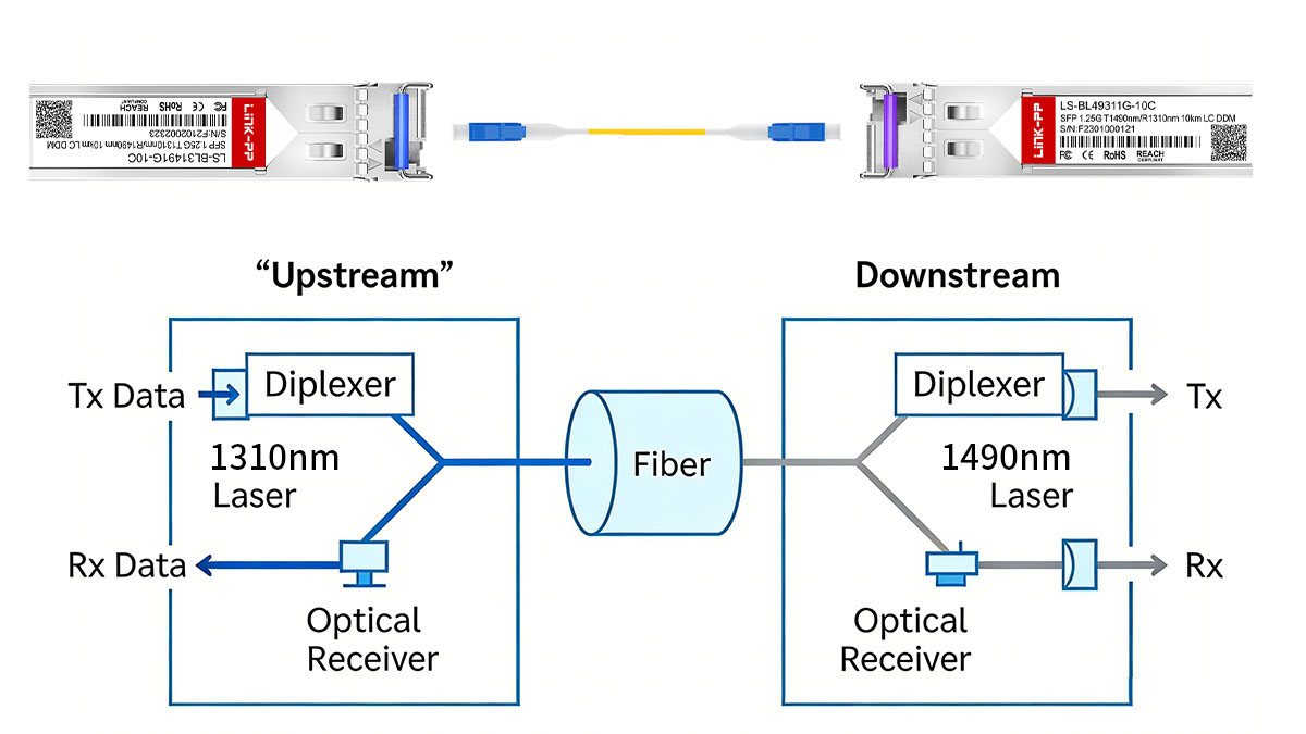
Simultaneous Transmit and Receive Process
In a 1000BASE-BX link, each transceiver operates with two optical paths internally: one for transmitting and one for receiving. These paths share the same fiber interface but are separated by a wavelength-selective filter inside the module.
The transmission process typically follows several coordinated steps.
-
The transmitting device converts Ethernet data into an optical signal at its designated wavelength.
-
The optical signal enters the fiber through the transceiver interface.
-
The signal travels through the fiber to the remote device.
-
The receiving module filters the incoming light to detect only the intended wavelength.
-
The optical signal is converted back into an electrical signal for the PHY layer.
Because the transmit wavelength of one device matches the receive wavelength of the other, both devices can communicate simultaneously over the same fiber.
| Device |
Transmit Wavelength |
Receive Wavelength |
| Endpoint A |
1310nm |
1270nm |
| Endpoint B |
1270nm |
1310nm |
This complementary configuration ensures that each transmitted signal is correctly received by the opposite endpoint.
The WDM filter inside the transceiver prevents the outgoing signal from interfering with the receiver even though both share the same fiber path. As a result, full-duplex data transmission is maintained without requiring separate physical channels.
Before data transmission begins, the devices at both ends of the link must establish a stable physical connection. The initialization process involves PHY layer synchronization, signal detection, and link validation.
Typical link establishment steps include:
-
Optical signal detection
Each receiver checks for the presence of an incoming optical signal from the remote device.
-
Clock synchronization
The PHY recovers the embedded clock signal from the received data stream.
-
Encoding alignment
The PCS layer ensures that 8B/10B encoded symbols are properly aligned.
-
Link confirmation
Once synchronization is achieved, the PHY signals the MAC layer that the link is active.
In many implementations, auto-negotiation may also be supported through the Ethernet control mechanisms, allowing devices to confirm compatible link parameters.
Once the link initialization process is complete, the two devices can exchange Ethernet frames continuously, with transmit and receive signals traveling in opposite directions through the same fiber using their assigned wavelengths.
?️? Advantages of 1000BASE-BX Technology
1000BASE-BX provides several practical benefits compared with traditional dual-fiber Gigabit Ethernet standards. By enabling bidirectional transmission over a single strand of single-mode fiber, the technology reduces infrastructure requirements while maintaining standard Ethernet performance and compatibility.
These advantages make the standard particularly valuable in environments where fiber resources are limited or where expanding the physical cabling infrastructure would be complex or expensive.
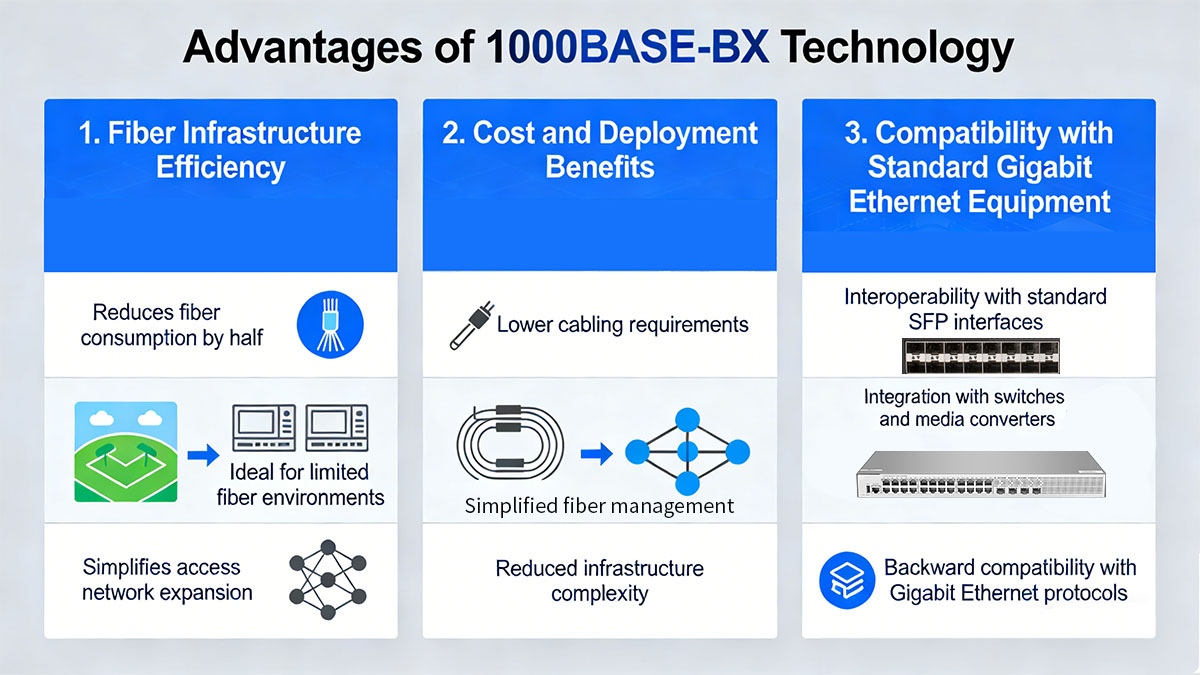
Fiber Infrastructure Efficiency
One of the most important advantages of 1000BASE-BX is its ability to reduce fiber consumption. Because both transmit and receive signals share the same fiber, only one strand is required to establish a full-duplex Gigabit Ethernet link.
The difference in fiber usage between common Gigabit optical standards can be summarized below.
| Standard |
Fiber Requirement |
Transmission Type |
| 1GBASE-SX |
Two fibers |
Multimode dual-fiber |
| 1GBASE-LX |
Two fibers |
Single-mode dual-fiber |
| 1GBASE-BX |
One fiber |
Single-mode bidirectional |
Reducing the fiber requirement by half can be especially valuable in large network infrastructures where fiber availability is limited or where existing cable ducts cannot easily accommodate additional fiber runs.
Cost and Deployment Benefits
Single-fiber transmission also simplifies network deployment and can lower overall infrastructure costs. When fewer fibers are required for each link, organizations can expand their network connectivity without extensive cabling upgrades.
Several operational advantages arise from this design.
-
Reduced cabling requirements
Fewer fiber strands are needed to establish long-distance Ethernet links.
-
Simplified fiber management
Network administrators manage fewer fiber connections and patch panel ports.
-
Efficient use of existing infrastructure
Existing fiber routes can support more network links without additional cabling.
-
Improved scalability
Networks can expand while conserving limited fiber resources.
These benefits are particularly noticeable in metropolitan access networks, campus environments, and multi-building enterprise deployments.
Compatibility with Standard Gigabit Ethernet Equipment
Although 1000BASE-BX uses a different optical transmission method, it remains compatible with the standard Gigabit Ethernet architecture. The PHY layer structure and data encoding mechanisms are consistent with other 1000BASE-X technologies.
The following table highlights how 1000BASE-BX maintains compatibility within the broader Ethernet ecosystem.
| Compatibility Aspect |
Description |
| Ethernet protocol |
Uses standard Gigabit Ethernet frame format |
| PHY architecture |
Based on the 1000BASE-X PCS, PMA, and PMD structure |
| Interface format |
Typically implemented in SFP optical transceivers |
| Network equipment |
Supported by switches, routers, and media converters |
Because the technology follows established Ethernet standards, network devices can integrate BX transceivers without requiring modifications to the higher layers of the network stack.
This compatibility allows organizations to deploy single-fiber links while maintaining interoperability with existing Gigabit Ethernet infrastructure.
?️? Common Applications of 1000BASE-BX
1000BASE-BX is widely used in network environments where fiber resources are limited but reliable Gigabit Ethernet connectivity is required. Because the technology supports bidirectional communication over a single strand of single-mode fiber, it is particularly suitable for access networks, distributed campus infrastructures, and remote connectivity scenarios.
By reducing the number of fibers required for each link, 1000BASE-BX helps organizations expand network capacity while maintaining efficient use of existing fiber infrastructure.
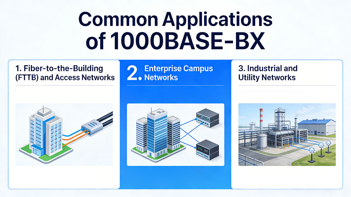
Fiber-to-the-Building (FTTB) and Access Networks
One of the most common deployment environments for 1000BASE-BX is Fiber-to-the-Building (FTTB) and other access network architectures. Internet service providers and telecommunications operators often deploy large numbers of optical links between central offices and end-user locations. In these environments, conserving fiber resources is essential.
Typical access network applications include:
-
Building connectivity in residential or commercial complexes
-
Links between central office equipment and access switches
-
Aggregation connections for subscriber networks
-
Extension of Ethernet services to remote sites
| Access Network Element |
Role of 1000BASE-BX |
| Central office switch |
Provides upstream connectivity |
| Access switch |
Distributes network services to users |
| Optical link |
Carries bidirectional Gigabit traffic |
| Single-mode fiber |
Enables long-distance transmission |
Using single-fiber connections allows service providers to connect more buildings or customers without deploying additional fiber cables.
Enterprise Campus Networks
Enterprise campuses often include multiple buildings spread across large areas. Interconnecting these buildings typically requires optical fiber links that support high bandwidth and reliable transmission.
1000BASE-BX can simplify these deployments by reducing the number of fibers required between network distribution points.
Common campus network scenarios include:
-
Inter-building backbone connections
-
Links between core switches and distribution switches
-
Network expansion in campuses with limited fiber pathways
-
Upgrades of legacy fiber links without installing additional cables
| Campus Network Link |
Typical Requirement |
Benefit of BX |
| Core to distribution |
High bandwidth connectivity |
Uses single fiber |
| Building interconnect |
Long-distance communication |
Supports up to 10km |
| Fiber-constrained pathways |
Limited cable capacity |
Reduces fiber usage |
Because many campus networks already use single-mode fiber for backbone connections, integrating 1000BASE-BX modules can provide an efficient way to extend network reach.
Industrial and Utility Networks
Industrial facilities, transportation infrastructure, and utility networks often operate across wide geographic areas. Network links may span long distances between control centers, monitoring stations, and remote equipment.
In these environments, installing additional fiber infrastructure can be difficult due to terrain, cost, or regulatory constraints. Single-fiber Ethernet links can therefore offer practical advantages.
Typical industrial deployments include:
-
Power grid monitoring systems
-
Railway communication networks
-
Oil and gas facility connectivity
-
Remote monitoring and control systems
| Industrial Network Scenario |
Connectivity Need |
Advantage of 1000BASE-BX |
| Power substations |
Reliable long-distance links |
Reduces fiber requirements |
| Transportation systems |
Distributed control networks |
Supports stable Gigabit communication |
| Remote monitoring sites |
Limited fiber infrastructure |
Enables bidirectional links on one fiber |
In these applications, the ability to deliver stable Gigabit Ethernet communication over a single fiber strand helps simplify network design while supporting reliable long-distance connectivity.
?️? Deployment Considerations for 1000BASE-BX Links
Deploying 1000BASE-BX links requires attention to several optical and network design factors to ensure stable communication. Although the technology simplifies fiber infrastructure by using a single strand for bidirectional transmission, correct module pairing, proper link budgeting, and careful network planning are still essential for reliable operation.
The following considerations help network engineers avoid common deployment issues and maintain consistent link performance.
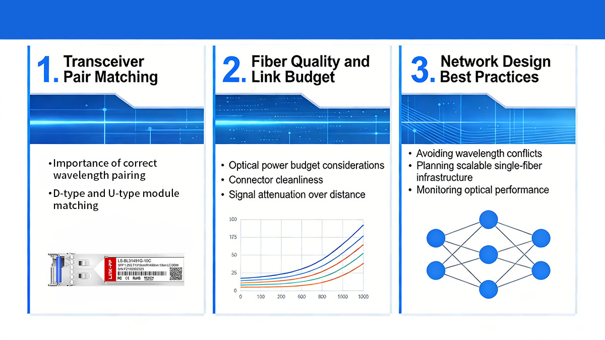
Transceiver Pair Matching
A 1000BASE-BX link operates only when complementary transceivers are paired correctly. Each module uses a different transmit and receive wavelength, so both ends of the link must use opposite wavelength configurations.
If identical modules are installed on both ends, both devices will transmit at the same wavelength and expect to receive a different one, preventing the link from establishing.
Correct pairing typically follows this pattern:
| Module Type |
Transmit Wavelength |
Receive Wavelength |
Deployment Role |
| BX Downstream |
1490nm |
1310nm |
One side of the link |
| BX Upstream |
1310nm |
1490nm |
Opposite side of the link |
When installing the modules, engineers should verify the wavelength specifications printed on the transceiver label or listed in the module documentation. Using the correct complementary pair ensures that each device receives the optical signal transmitted by the other.
Fiber Quality and Link Budget
Even though 1000BASE-BX reduces fiber requirements, the optical link must still meet power budget and attenuation limits to maintain reliable transmission.
Several physical factors influence optical performance:
-
Fiber attenuation over distance
Optical power decreases as the signal travels through the fiber.
-
Connector insertion loss
Each connector or patch point introduces small signal losses.
-
Splice losses
Fiber splicing points can reduce signal strength.
-
Optical receiver sensitivity
The receiver must detect signals above its minimum threshold.
A simplified example of typical optical considerations is shown below.
| Parameter |
Typical Value |
Impact on Link |
| Fiber type |
Single-mode (OS2) |
Supports long-distance transmission |
| Maximum distance |
up to 10km |
Defined by BX10 specification |
| Connector loss |
0.2–0.5dB |
Accumulates across patch panels |
| Fiber attenuation |
~0.35dB/km at 1310nm |
Reduces optical power over distance |
During deployment, engineers should ensure that the total link loss does not exceed the supported optical power budget of the transceiver pair.
Network Design Best Practices
Proper network design can help avoid compatibility issues and ensure scalable single-fiber infrastructure. While 1000BASE-BX links are straightforward to deploy, certain practices improve operational reliability.
Key design considerations include:
-
Maintain clear wavelength pairing documentation
Tracking BX-D module and BX-U module placement helps prevent incorrect installations.
-
Plan fiber routes carefully
Single-fiber links should be clearly labeled to avoid accidental reconnection with dual-fiber systems.
-
Monitor optical signal levels
Many switches support digital optical monitoring, allowing engineers to track transmit power, receive power, and temperature.
-
Avoid mixing incompatible optics
Transceivers designed for different wavelengths or standards may not interoperate correctly.
By combining correct module pairing, proper optical budgeting, and careful network planning, organizations can deploy 1000BASE-BX links that deliver stable Gigabit Ethernet connectivity while maximizing fiber efficiency.
?️? 1000BASE-BX vs Other Gigabit Optical Standards
1000BASE-BX differs from other Gigabit Ethernet optical standards mainly in its transmission architecture. While most Gigabit fiber technologies rely on two fibers—one for transmitting and one for receiving—1000BASE-BX uses wavelength separation to support bidirectional communication over a single strand of single-mode fiber.
Understanding how BX compares with other widely used Gigabit optical standards helps network engineers choose the most appropriate solution for different deployment scenarios.
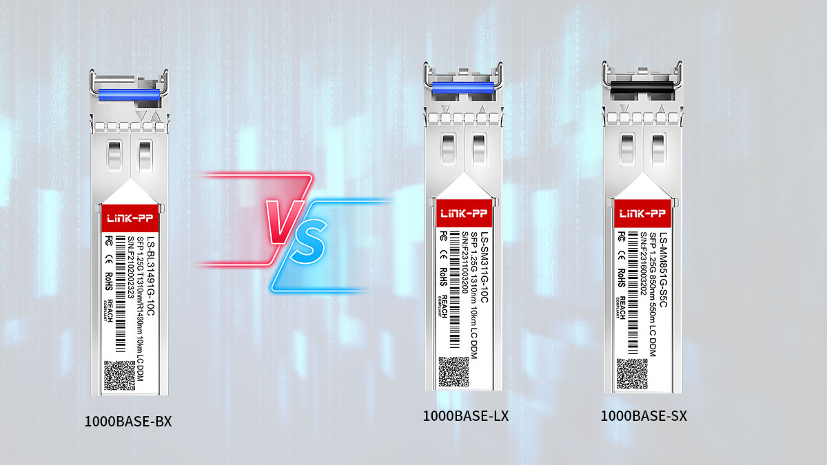
1000BASE-BX vs 1000BASE-LX
The primary difference between these two standards lies in fiber usage and transmission architecture. Both operate over single-mode fiber and support similar transmission distances, but they use different physical link designs.
| Standard |
Fiber Type |
Fiber Count |
Typical Reach |
| 1G LX |
Single-mode fiber |
Two fibers |
up to 10km |
| 1G BX |
Single-mode fiber |
One fiber |
up to 10km |
Because 1000BASE-LX uses separate fibers for transmit and receive paths, it relies on traditional duplex optical connections. In contrast, 1000BASE-BX uses WDM filters to separate two wavelengths on a single fiber.
In environments where fiber availability is limited—such as access networks or older campus infrastructures—1000BASE-BX can significantly improve fiber utilization. However, LX may still be preferred in networks where dual-fiber cabling is already widely deployed and wavelength pairing management is unnecessary.
1000BASE-BX vs 1000BASE-SX
These two standards differ in both fiber type and deployment environment. 1000BASE-SX is designed primarily for short-distance communication over multimode fiber, while 1000BASE-BX targets longer-distance links over single-mode fiber.
| Standard |
Fiber Type |
Typical Distance |
Common Environment |
| 1G SX |
Multimode fiber |
up to 550m |
Data centers and LANs |
| 1G BX |
Single-mode fiber |
up to 10km |
Access and campus networks |
Because multimode fiber is commonly used inside buildings or data centers, 1000BASE-SX is often deployed for short inter-switch connections. Its lower optical power requirements and compatibility with multimode infrastructure make it suitable for short-range networking.
In contrast, 1000BASE-BX is designed for longer links where single-mode fiber is available. Its single-fiber architecture provides additional benefits in outdoor networks or metropolitan deployments where fiber capacity must be used efficiently.
Choosing between these standards typically depends on three main factors:
-
existing fiber infrastructure
-
required transmission distance
-
fiber availability between network endpoints
By selecting the appropriate optical standard for the deployment environment, network designers can balance performance, infrastructure constraints, and long-term scalability.
?️? Future Role of Single-Fiber Ethernet Technologies
Single-fiber Ethernet technologies such as 1000BASE-BX demonstrate how optical networking can maximize existing fiber infrastructure while maintaining standard Ethernet performance. As network demand continues to grow across access networks, enterprise campuses, and distributed infrastructure, efficient use of fiber resources remains an important design consideration.
Although higher-speed Ethernet technologies are becoming increasingly common, the architectural concept used by 1000BASE-BX—bidirectional transmission using wavelength separation—continues to influence modern optical networking solutions.
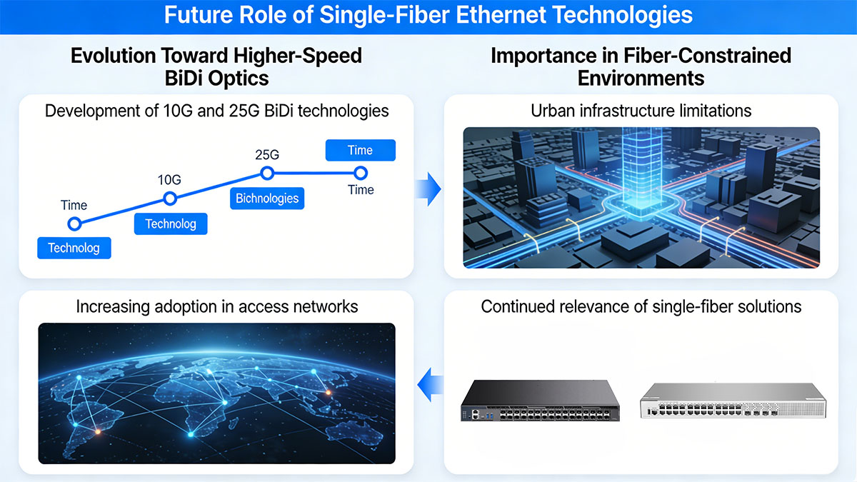
Evolution Toward Higher-Speed BiDi Optics
The principle of bidirectional communication over a single fiber has expanded beyond Gigabit Ethernet. Newer optical transceiver technologies apply similar wavelength multiplexing techniques to support higher data rates while preserving fiber efficiency.
Several higher-speed optical technologies now use similar design concepts.
| Technology |
Data Rate |
Transmission Method |
Typical Use Case |
| 1000BASE-BX |
1Gbps |
Single-fiber WDM |
Access and campus networks |
| 10G BiDi optics |
10Gbps |
Bidirectional wavelengths |
Enterprise backbone links |
| 25G BiDi optics |
25Gbps |
WDM-based bidirectional transmission |
Data center interconnects |
These technologies continue the same core idea: separating transmit and receive signals by wavelength rather than by fiber. By extending the concept to higher speeds, modern optical modules can increase network capacity while minimizing infrastructure expansion.
As network operators upgrade their infrastructure, this design approach remains useful in scenarios where deploying additional fibers would be expensive or physically difficult.
Importance in Fiber-Constrained Environments
Single-fiber Ethernet solutions remain particularly relevant in environments where fiber infrastructure is limited. Many existing networks were built with a fixed number of fiber strands, and expanding those routes may require costly construction or new cable installations.
Common situations where single-fiber technologies remain valuable include:
-
metropolitan access networks with limited duct capacity
-
legacy campus infrastructure with restricted fiber counts
-
industrial or transportation networks covering large geographic areas
-
remote monitoring systems connected through long-distance fiber routes
In these environments, bidirectional optical technologies allow organizations to extend network connectivity without increasing fiber requirements.
As a result, while higher-speed Ethernet standards continue to evolve, the operational advantages demonstrated by technologies such as 1000BASE-BX ensure that single-fiber optical networking remains a relevant and practical design approach in modern communication infrastructure.
?️? Conclusion
1000BASE-BX provides a practical approach to Gigabit Ethernet connectivity by enabling full-duplex communication over a single strand of single-mode fiber. By combining wavelength division multiplexing with the standard Ethernet PHY architecture, the technology allows transmit and receive signals to operate simultaneously on different wavelengths while maintaining compatibility with the broader 1000BASE-X framework.
Understanding the structure of the 1000BASE-BX standard—from its wavelength pairing mechanism to the roles of the PCS, PMA, and PMD sublayers—helps network engineers design and deploy reliable single-fiber links. These capabilities make the technology particularly valuable in environments where fiber availability is limited, such as access networks, campus infrastructures, and distributed industrial systems.
Although newer optical technologies continue to increase network speeds, the underlying principle used by 1000BASE-BX—efficient fiber utilization through bidirectional wavelength separation—remains an important concept in modern optical networking.
For network designers planning single-fiber Gigabit deployments or exploring compatible optical modules, reviewing detailed specifications and implementation options can help ensure reliable operation. More information about supported optical transceivers and networking solutions is available at the LINK-PP Official Store.


