Have you ever wondered how industrial network infrastructures maintain seamless, high-speed connectivity under demanding operational conditions? In modern enterprise and industrial environments, achieving this level of reliability often comes down to dependable Gigabit Ethernet components like the TN-SFP-GE-S optical transceiver. As a ruggedized, small form-factor pluggable module, it serves as a critical link that keeps data moving steadily through complex network architectures.
But what exactly makes this industrial-grade module so effective at handling high-volume Gigabit traffic across fiber optic media? By bridging host switches with fiber cabling, it ensures low-latency data transmission while strictly adhering to rigorous multi-source agreements. Exploring its underlying hardware protocols and physical layer specifications is the key to unlocking its full potential in your network deployment.
🔷 Introduction to the Lantronix TN-SFP-GE-S Optical Transceiver
The Lantronix TN-SFP-GE-S optical transceiver is a high-performance, industrial-grade module designed to deliver stable Gigabit Ethernet connectivity over fiber optic cabling. It serves as a critical component in bridging network switches and routers with physical fiber media, ensuring efficient data transmission. Gaining a clear understanding of its foundational architecture and deployment scenarios is essential for optimizing modern network infrastructure.

Form Factor Architecture and Core Hardware Classification
The TN-SFP-GE-S utilizes the industry-standard Small Form-factor Pluggable (SFP) architecture, featuring a metal housing designed for high-density port configurations. Its hot-swappable mechanical design includes a bail clasp latching mechanism for secure insertion and easy removal from the host SFP cage.
Internally, the module integrates a printed circuit board (PCB) featuring an application-specific integrated circuit (ASIC) alongside an onboard EEPROM chip. Classified as an industrial-grade transceiver, it features upgraded internal components, premium solder joints, and heavy-duty electrical traces built to handle continuous operations under physical stress.
Industry Standards Compliance and Multi-Source Agreement (MSA) Alignment
Adherence to strict standardization ensures that the TN-SFP-GE-S operates reliably and maintains high signal integrity during continuous operation. The module fully aligns with the INF-8074i Multi-Source Agreement (MSA), which dictates precise physical dimensions, cage mating requirements, and the standard 20-pin electrical connector layout.
By strictly following these shared industry guidelines, the transceiver guarantees that its mechanical dimensions and pin layouts match exact industry expectations. This rigorous alignment ensures stable system integration, proper diagnostic register maps, and dependable electrical performance whenever the module is deployed in standard-compliant hardware slots.
Target Network Deployments and Enterprise Infrastructure Use Cases
This optical module is primarily engineered for short-reach data transmissions within localized network environments utilizing multi-mode fiber backbones. It is widely deployed in enterprise data centers, corporate building backbones, and campus networks to establish rapid, reliable server-to-switch links.
Additionally, its industrial-grade classification makes it highly suitable for harsh environments like factory floors and outdoor telecom enclosures. In these demanding scenarios, the module effectively maintains stable Gigabit speeds for critical automated machinery, programmable logic controllers (PLCs), and IP surveillance systems.
🔷 Physical Layer Specifications of the TN-SFP-GE-S Module
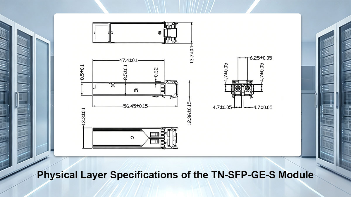
The physical layer specifications of the TN-SFP-GE-S module define its core hardware capabilities and optical performance limits. These parameters outline how the transceiver transmits and receives light signals through fiber optic cables to maintain a stable connection. Reviewing these physical hardware details ensures the module matches your network's cabling and power requirements.
Optical Transmitter and Laser Diode Classification
The TN-SFP-GE-S utilizes a high-efficiency internal laser diode designed specifically for short-range optical signaling over multi-mode fiber. This transmitter architecture converts incoming electrical data streams into precise, high-speed light pulses.
The primary electrical and optical performance metrics for this transmitter include the following:
- Laser Type: Vertical-Cavity Surface-Emitting Laser (VCSEL).
- TX Power Range: -9 to 0dBm.
Receiver Type and Photodetector Sensitivity
On the receiving end, the module features a highly sensitive photodetector assembly that captures incoming light signals from the optical link. This component accurately reverses the conversion process, turning light pulses back into clean electrical signals for the host switch.
Key performance metrics and limits for the receiver hardware include the following:
- Receiver Type: PIN photodiode.
- Receiver Sensitivity: < -18dBm.
- Maximum Input Power (Overload): -1dBm.
Central Wavelength and Spectral Width Parameters
Optical communication relies on strict wavelength management to prevent signal degradation and ensure compatibility across fiber networks. The TN-SFP-GE-S operates within a specific near-infrared spectrum optimized for short-wavelength multi-mode data transmissions.
The exact wavelength properties that govern this optical module include the following:
- Central Wavelength: 850nm.
- Wavelength Range: 830nm to 870nm.
Connector Interface and Mechanical Dimensions
The physical footprint and connector design of the module are built to match standard network patching infrastructure. Its compact size ensures it fits tightly into high-density switch ports while offering a secure mechanical locking interface.
The physical dimensions and connection specifications for the hardware include the following:
- Connector Type: Duplex LC interface.
- Module Dimensions: Approx. 8mm x 13mm x 55mm.
- Latch Mechanism: Bail clasp color-coded black for Gigabit SX identification.
🔷 Media and Distance Limits for TN-SFP-GE-S Deployments
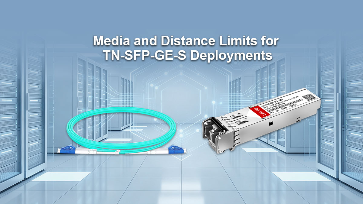
Deploying the TN-SFP-GE-S optical transceiver requires a clear understanding of the specific fiber media limits and distance thresholds that govern short-wavelength transmissions. Because this module is engineered for localized networks, its performance depends directly on the core diameter and quality of the physical cabling. Mapping out these boundaries prevents signal degradation and ensures stable link operations across the entire network layout.
Multi-Mode Fiber Core Diameters and Compatibility
The TN-SFP-GE-S is designed exclusively for multi-mode fiber (MMF) infrastructures, supporting both legacy and modern cabling standards. It features full compatibility with traditional light-guiding cores as well as laser-optimized glass options.
The following table details the maximum supported transmission distances across different multi-mode fiber core diameters:
| Fiber Core Diameter (µm) | Fiber Type Classification | Maximum Transmission Distance |
| 50/125µm | OM2 / OM3 / OM4 | 550m transmission with 50/125µm MMF |
| 62.5/125µm | OM1 | 300m transmission with 62.5/125µm MMF |
Maximum Link Lengths and Reach Boundaries
The strict reach boundaries of the TN-SFP-GE-S are dictated by the physical characteristics of 850nm light passing through glass. Exceeding these maximum distances will result in high bit error rates or a complete loss of signal synchronization between host devices.
When planning network runs, engineers must calculate the exact physical routing distance rather than estimating straight-line lengths. It is crucial to account for patch panel bridges and service loops, as these add hidden physical distance to the overall reach boundary.
Modal Bandwidth Variations and Signal Attenuation Factors
Signal reach is heavily influenced by modal bandwidth, which measures how much information a fiber core can carry over a specific distance without data overlapping. Older OM1 cabling offers lower modal bandwidth, which causes the light pulses to spread out and limits transmission to shorter distances.
Additionally, physical signal attenuation constantly degrades the light beam as it travels down the core. Natural glass impurities, macro-bends in the conduit, and tight cable ties all absorb or scatter the 850nm optical energy, weakening the signal before it reaches the receiver.
Optical Power Budget and Insertion Loss Calculations
To guarantee a reliable connection, the total insertion loss of a fiber run must never exceed the module's calculated optical power budget. This budget represents the difference between the minimum transmitter output power and the maximum receiver sensitivity.
Network installers must calculate all accumulated loss factors, including fiber attenuation per kilometer, mechanical splices, and patch panel connections. If the total insertion loss is too high, the signal will fall below the receiver threshold, causing intermittent link drops or packet loss.
🔷 Supported Data Rates and Network Protocols of TN-SFP-GE-S
The TN-SFP-GE-S optical transceiver is designed to handle multiple high-speed communication standards across various network environments. It incorporates versatile internal programming that allows it to process different data packet structures without losing synchronization or speed. Understanding these supported protocols ensures that the module matches the specific traffic requirements of your storage and enterprise networks.
1000BASE-SX Gigabit Ethernet IEEE 802.3z Compliance
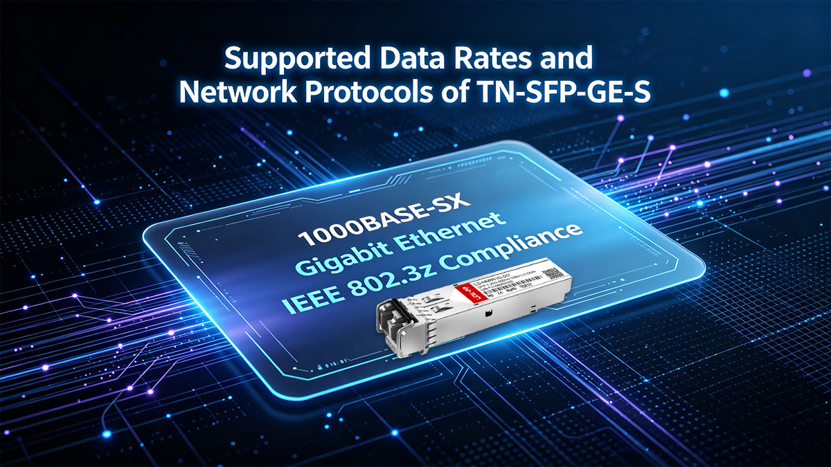
The primary function of this transceiver is to deliver high-speed local area network connectivity under the industry-standard Gigabit Ethernet framework. It strictly follows the rules defined by the IEEE 802.3z committee, which governs short-wavelength optical transmissions. This ensures that the module handles data framing, timing, and error checks perfectly within your local infrastructure.
The core performance elements and standards for this Ethernet protocol include the following:
- Operating Data Rate: Fixed at 1.25Gbps.
- Standard Name: IEEE 802.3z 1000BASE-SX.
- Coding Scheme: Uses 8B/10B line encoding.
- Primary Application: High-speed LAN switch connections.
Fibre Channel FC-PI Protocol Support
Beyond standard local area networking, this versatile module is capable of operating within specialized storage area networks (SANs). It features hardware compatibility with the Fibre Channel physical interface standards to facilitate fast block-level data storage retrieval. This makes it an excellent choice for connecting host bus adapters directly to storage arrays.
The technical parameters supporting this specialized storage network protocol include the following:
- Protocol Standard: Fibre Channel FC-PI compliant.
- Supported Speed: 1x Fibre Channel operations.
- Transmission Rate: Stable 1.0625 Gbps data flow.
- Target Environment: Data center storage arrays.
🔷 Electrical Interface and Pin Configuration of TN-SFP-GE-S
The electrical interface of the TN-SFP-GE-S dictates how the transceiver communicates directly with the host network switch's internal circuitry. This hardware boundary uses a precise series of gold-plated contacts to transmit high-speed data, deliver power, and share vital control signals. Understanding this pin configuration ensures proper alignment and prevents electrical damage during installation.
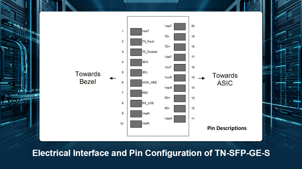
20-Pin SFP Connector Definition and Signal Assignment
The physical connection to the host equipment relies on a standardized 20-pin card-edge connector located at the rear of the module. These pins are split evenly across the top and bottom sides of the internal printed circuit board to handle different hardware tasks. They are designated for specific electrical functions like ground tracking, power delivery, and low-speed control communication.
The specific categories and assignments for these electrical contacts include the following:
- GND Pins: Multiple chassis and signal grounds.
- TX_Fault Pin: Indicates laser hardware errors.
- TX_Disable Pin: Shuts off the optical transmitter.
- MOD_DEF Pins: Handles I²C serial communication.
- RX_LOS Pin: Signals a lost optical connection.
High-Speed Differential Signaling (PECL/CML)
To transfer data rapidly without interference, the module uses low-voltage differential signaling across its primary transmit and receive paths. This design splits data into matching positive and negative voltage streams to cancel out electromagnetic noise from adjacent components. It guarantees that high-frequency data integrity remains intact as signals pass between the transceiver and the host ASIC.
The electrical logic and signaling standards used for data transfer include the following:
- TX Data Logic: Positive Emitter-Coupled Logic (PECL).
- RX Data Logic: Current Mode Logic (CML).
- Signal Lines: TD+/- and RD+/- differential pairs.
- Impedance Matching: Strict 100-ohm differential routing.
Power Supply Voltage and Maximum Current Consumption
The TN-SFP-GE-S draws its operational power directly from the host switch cage through dedicated power supply contacts. The internal circuitry requires a highly stable voltage level to keep the optical laser and receiver functioning within their specified performance thresholds. Exceeding the maximum current allowances can overheat the internal components and degrade performance.
The power delivery parameters and limitations for this module include the following:
- Supply Voltage: Fixed 3.3V nominal rating.
- Voltage Tolerance: Plus or minus 5 percent.
- Max Current: Under 300mA total consumption.
- Power Consumption: Less than 1W maximum.
Hot-Plugging Circuitry and Inrush Current Protection
This transceiver features a specialized mechanical and electrical architecture that allows full hot-plugging capability inside live network cages. The individual pins on the edge connector are manufactured with varying lengths to ensure ground contacts engage before power lines connect. This layout prevents dangerous voltage spikes and protects the host system from sudden electrical shorts.
The built-in protective features for live component swapping include the following:
- Staggered Pin Lengths: Guarantees proper grounding order.
- Inrush Current Limiting: Prevents sudden voltage drops.
- Hot-Swappable Design: Safe installation without system reboots.
- ESD Suppression: Shields internal chips from static.
🔷 Digital Optical Monitoring (DOM) Capabilities in TN-SFP-GE-S
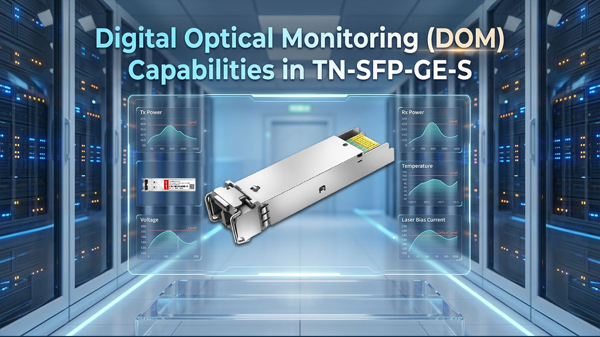
Digital Optical Monitoring (DOM) is an advanced hardware feature that provides real-time tracking of the module's operational performance. By utilizing internal sensors, the transceiver continuously measures critical metrics such as optical power, internal temperature, and voltage levels. This diagnostic capability allows network administrators to proactively spot potential link failures and maintain high infrastructure uptime without disrupting live traffic.
Real-Time Monitoring Diagnostics (SFF-8472 Implementation)
The DOM functionality built into the TN-SFP-GE-S operates according to the rigorous industry-standard SFF-8472 specification. This protocol governs how internal analog sensor data is converted into digital readings that the host switch can easily interpret. By standardizing this diagnostic framework, the transceiver ensures that its performance metrics are consistently reported across different monitoring software systems.
The core parameters tracked by this real-time monitoring implementation include the following:
- Laser Transmit Power: Measures active optical output.
- Receiver Optical Power: Tracks incoming light levels.
- Internal Module Temperature: Monitors real-time thermal conditions.
- Supply Voltage Levels: Tracks active Vcc power.
- Laser Bias Current: Monitors the transmitter drive current.
Transmit/Receive Optical Power Thresholds and Alarms
To protect the network from sudden drops in signal quality, the module features preset hardware alarm and warning thresholds for optical power. If the light levels drop too low due to dirty fiber or spike too high from an overload, the internal circuitry flags the issue instantly. This immediate alert system gives engineers plenty of time to troubleshoot the fiber link before a complete connection outage occurs.
The automated warning and error indicators managed by these thresholds include the following:
- TX High/Low Alarms: Flags abnormal laser output.
- RX High/Low Alarms: Warns of extreme incoming light.
- TX/RX Warning Flags: Signals minor, non-critical power drifts.
- Automated Interrupts: Notifies host software of threshold breaks.
Supply Voltage and Internal Temperature Telemetry
Maintaining stable electrical and thermal levels is critical for preventing the industrial-grade transceiver from experiencing permanent hardware degradation. The internal telemetry system acts as a digital multi-meter, continuously tracking the precise case temperature and supply voltage filtering into the module. This constant monitoring is especially useful in harsh factory or outdoor setups where environmental conditions shift rapidly.
The telemetry readouts provided by this integrated tracking feature include the following:
- Voltage Monitoring Range: Tracks standard 3.3V power stability.
- Temperature Resolution: Provides precise, granular thermal data.
- Operating Range Alerts: Warns when environmental thresholds are broken.
- Historical Logging Support: Provides data for system health trends.
I²C Serial Interface Control and Memory Map Register Access
The host network switch accesses all internal DOM diagnostics using a two-wire I²C serial communication interface. This control protocol reads data directly from a split memory architecture located on the module’s onboard EEPROM chip. By assigning distinct memory addresses for configuration settings and sensor data, the switch can cleanly retrieve statistics without interfering with the hardware's primary data transmission path.
The primary attributes of this internal memory control interface include the following:
- Interface Protocol: Standard two-wire I²C serial bus.
- Base EEPROM Address: Fixed at 0xA0 for standard ID.
- DOM Diagnostic Address: Fixed at 0xA2 for sensor data.
- Register Access Type: Read-only access for real-time telemetry.
🔷 Environmental and Thermal Tolerances of TN-SFP-GE-S
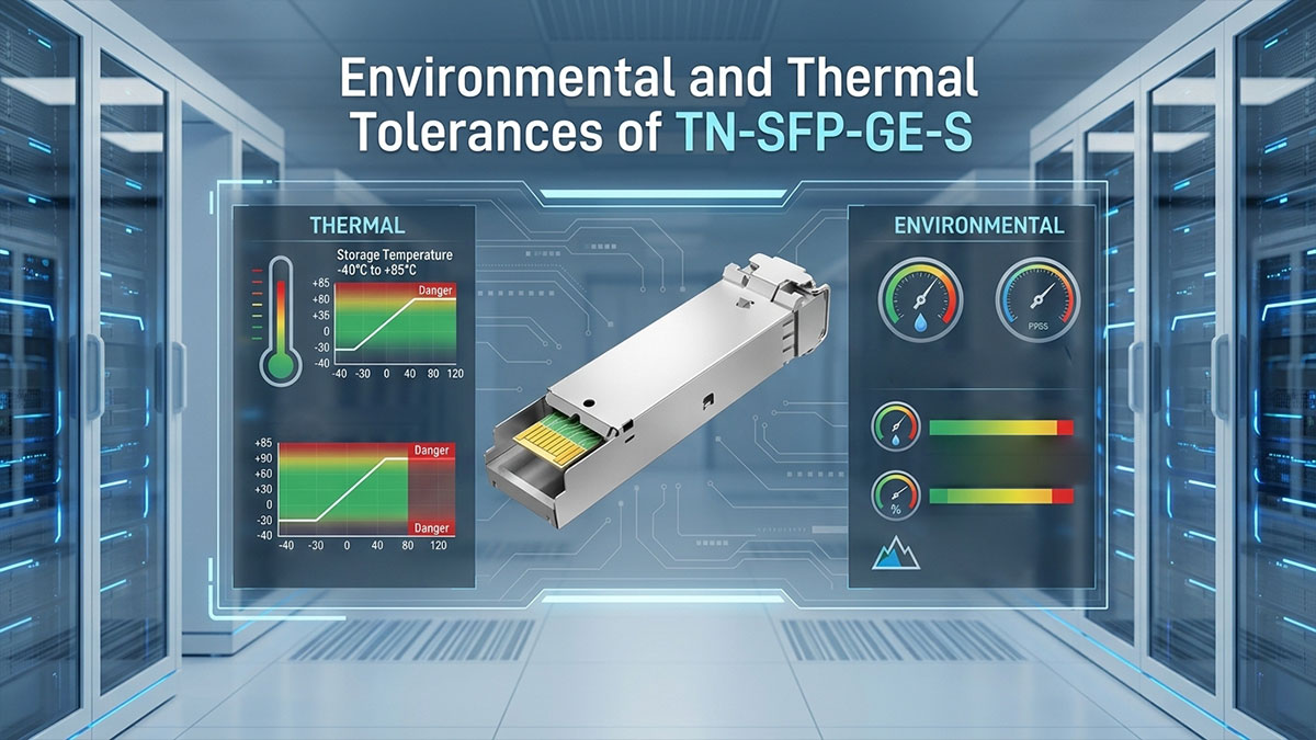
The environmental and thermal tolerances of the TN-SFP-GE-S define the physical boundaries within which the module can safely operate without sacrificing performance. Because this transceiver is built for industrial-grade deployments, its internal architecture is reinforced to withstand extreme temperature swings and high humidity. Reviewing these structural tolerances ensures that the hardware remains durable and reliable when deployed in harsh field environments.
Operating Case Temperature Ranges
The TN-SFP-GE-S is specifically engineered to maintain stable optical connections across an expanded industrial temperature range. Unlike standard commercial modules that fail under extreme heat or cold, this hardware utilizes specialized internal components that resist thermal drifting.
This robust thermal design allows the module to operate flawlessly at case temperatures ranging from -40°C up to 85°C. Such an extended range guarantees that the internal laser diode and receiver maintain their exact power calibrations even in unconditioned environments.
Storage Temperature Limits and Relative Humidity Tolerances
When the module is kept in reserve or transported to a deployment site, it must be protected from environmental degradation. The passive components are rated to withstand a deep storage temperature range from -40°C to 85°C without experiencing structural or physical decay.
Additionally, the transceiver features a tightly sealed housing designed to handle non-condensing relative humidity levels from 5% up to 85%. This high tolerance prevents moisture accumulation on the internal printed circuit board, stopping corrosion before the hardware is ever installed.
Thermal Dissipation and Airflow Management in High-Density Chassis
Deploying multiple modules into a high-density network switch cage generates concentrated pockets of heat that must be managed efficiently. The TN-SFP-GE-S features a premium metal alloy shell that acts as a passive heat sink, drawing warmth away from the delicate internal laser.
Proper chassis airflow management is critical to ensure that this dissipated heat is swept away by the host system’s cooling fans. If airflow is blocked, heat buildup can trigger internal DOM alarms, degrade transmitter efficiency, and drastically shorten the operational lifespan of the hardware.
Electrostatic Discharge Protection and Electromagnetic Interference Shielding
Industrial environments often expose networking hardware to severe electrical noise and static buildup from heavy machinery. To counter this, the module incorporates robust built-in electrostatic discharge (ESD) protection circuitry to safely neutralize sudden voltage shocks during handling.
Furthermore, its fully enclosed metal housing provides exceptional electromagnetic interference (EMI) shielding. This shielding prevents external radio frequencies from corrupting the high-speed data path while simultaneously keeping the transceiver’s own emissions well below strict regulatory limits.
🔷 Hardware Compatibility and Interoperability Checklist for TN-SFP-GE-S
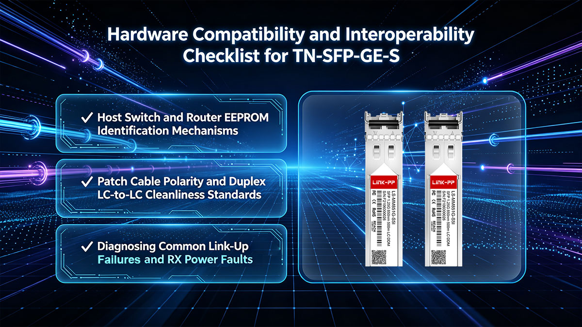
Establishing seamless hardware compatibility is a vital step in ensuring the TN-SFP-GE-S integrates smoothly into your existing network setup. Even though the module adheres to strict physical dimensions, the host equipment must recognize its internal programming before establishing a link. Following a structured hardware checklist helps prevent configuration errors and guarantees stable communication between your switches and routers.
Host Switch and Router EEPROM Identification Mechanisms
When the TN-SFP-GE-S is inserted into a host port, the switch immediately reads the module's onboard EEPROM chip via the I²C serial interface. This memory chip contains specific vendor codes, part numbers, and serialization data that identify the transceiver's capabilities.
The host operating system analyzes these standardized data registers to verify the module's speed, wavelength, and overall hardware compliance. If this identification check fails, the host switch may flag the port as unsupported or completely disable traffic forwarding through that specific slot.
Patch Cable Polarity and Duplex LC-to-LC Cleanliness Standards
A successful fiber connection requires maintaining proper optical polarity across the duplex LC-to-LC patch cabling system. The transmit (TX) fiber on one end of the link must connect directly to the receive (RX) port on the opposite transceiver.
Additionally, maintaining strict physical cleanliness standards on the fiber end-faces is critical to prevent light scattering. Microscopic dust particles or oil smudges on the LC connectors will block the 850nm light beam, leading to high insertion loss and intermittent signal drops.
Diagnosing Common Link-Up Failures and RX Power Faults
When a link fails to initialize, technicians should immediately check the digital optical monitoring data to read the active RX power levels. A low or non-existent RX power reading usually points to a broken fiber core, mismatched polarity, or severely dirty connectors along the cable run.
If the RX power is within the normal specification but the link remains down, the issue may stem from a speed mismatch on the host port configuration. Forcing the switch port to a fixed 1000Mbps speed rather than relying on auto-negotiation often resolves these stubborn synchronization errors.
🔷 Final Technical Overview of the Lantronix TN-SFP-GE-S Module

The Lantronix TN-SFP-GE-S optical transceiver serves as a high-reliability hardware solution for short-reach 1000BASE-SX Gigabit Ethernet layers, seamlessly converting electrical serialized data into high-speed 850nm VCSEL optical pulses. By anchoring its design to the INF-8074i and SFF-8472 industry standards, the module guarantees exceptional signal integrity, low-latency transmission, and precise real-time diagnostic telemetry across extended industrial thermal gradients. Ultimately, its ruggedized physical layer architecture makes it an indispensable asset for sustaining deterministic performance within high-density enterprise and industrial backbones.
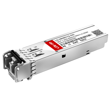
When managing large-scale network expansions, engineers often evaluate reliable secondary sources that match these exact industrial specifications to balance project budgets. A highly regarded alternative in the industry is the LINK-PP LS-MM851G-S5I 1000BASE-SX SFP, which offers identical 850nm optical characteristics and robust thermal performance. To explore this compatible hardware solution or to review comprehensive datasheets for your infrastructure planning, feel free to visit the LINK-PP Official Store.