Modern network infrastructure continues to evolve toward higher data rates, greater port density, and increasingly compact hardware designs. As switches, routers, and optical transport systems handle larger volumes of traffic, maintaining signal integrity and operational stability becomes more challenging. Electromagnetic interference (EMI) and excessive heat are two critical factors that can negatively affect network performance, equipment reliability, and long-term system efficiency.
A Cage SFP plays a much larger role than simply holding an optical transceiver in place. Its metal enclosure helps control electromagnetic emissions, supports grounding continuity, and contributes to heat dissipation within networking equipment. As transmission speeds increase and deployment environments become more demanding, understanding the EMI and thermal shielding functions of Cage SFP assemblies becomes essential for network designers, engineers, and infrastructure operators.
This article explores several key aspects of Cage SFP technology, including:
-
The structure and purpose of Cage SFP assemblies
-
The fundamentals of EMI shielding in high-speed networks
-
Thermal management challenges and heat dissipation mechanisms
-
Design features that enhance shielding effectiveness
-
Industry standards, compliance requirements, and deployment practices
-
Future developments in shielding and thermal control technologies
By understanding these factors, organizations can better evaluate Cage SFP designs and their contribution to reliable, high-performance optical networking environments.
? What Is a Cage SFP?
A Cage SFP is a mechanical and electrical housing structure designed to securely hold Small Form-Factor Pluggable (SFP) optical transceiver modules within networking equipment such as switches, routers, and optical transport systems. It provides a standardized interface between the transceiver and the host device, ensuring stable physical connection, reliable signal transmission, and proper alignment during hot-swappable operations. In high-speed networking environments, the Cage SFP also plays a critical role in maintaining system stability under dense and electrically noisy conditions.
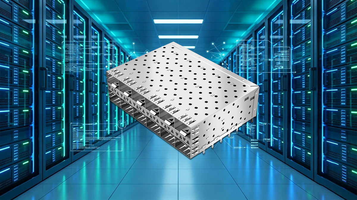
Beyond its mechanical function, a Cage SFP serves as an integrated part of the system’s electromagnetic and thermal control strategy. By using a conductive metal enclosure connected to the PCB ground plane, it helps reduce electromagnetic leakage and protects sensitive high-speed signals from external interference. At the same time, its physical structure supports airflow around the transceiver module, contributing indirectly to heat dissipation and overall thermal balance in densely populated port arrays.
Basic Structure of a Cage SFP Assembly
A Cage SFP assembly is composed of several precisely engineered components that work together to ensure mechanical stability, electrical grounding, and shielding performance. It forms the foundational interface between the host board and the optical module, directly influencing signal quality and system reliability.
The core structural elements typically include:
- Metal cage housing for mechanical enclosure and EMI containment
- Spring contacts (EMI fingers) for grounding continuity
- PCB-mounted connector alignment frame
- Latch and retention features for secure module insertion
These components ensure that the SFP module remains firmly seated while maintaining continuous electrical grounding. The precision of these mechanical interfaces directly affects insertion loss, signal integrity, and electromagnetic shielding effectiveness. The metal cage also helps define airflow pathways, which can influence thermal behavior in high-density deployments.
Purpose of the Cage in SFP-Based Systems
The primary purpose of a Cage SFP is to provide a stable, shielded, and thermally supportive environment for optical transceiver operation. While it physically secures the module, its broader function extends to maintaining system performance in electrically and thermally challenging environments.
Key functional roles include:
- Mechanical retention of hot-swappable SFP modules
- Establishment of a continuous ground path for EMI suppression
- Reduction of electromagnetic leakage between adjacent ports
- Support for controlled airflow across high-density port areas
These functions work together to ensure that high-speed optical signals remain stable even in environments with significant electromagnetic noise or heat accumulation. The cage effectively becomes part of the system-level design strategy for maintaining both electrical and thermal integrity.
Common Applications of Cage SFP Technology
Cage SFP structures are widely deployed across modern networking infrastructures where reliability, density, and performance are critical requirements. Their standardized design makes them suitable for a broad range of equipment types and operational environments.
Typical application scenarios include:
- Data center switching and aggregation platforms
- Enterprise core and edge networking equipment
- Telecommunications access and transport systems
- Industrial Ethernet systems operating in EMI-heavy environments
These environments often involve high port densities and elevated data rates, both of which increase the importance of effective shielding and thermal control. The Cage SFP provides a consistent foundation that allows optical transceivers to operate reliably across these diverse deployment conditions.
? Understanding EMI in High-Speed Networking Equipment
Electromagnetic interference (EMI) is a critical physical phenomenon in high-speed networking systems where unwanted electromagnetic energy disrupts signal transmission and degrades overall system performance. In optical and electrical interconnect environments, EMI can originate from nearby electronic components, power circuits, or even adjacent high-speed data lanes. As data rates increase, the tolerance for electromagnetic noise becomes significantly lower, making EMI control a fundamental requirement for maintaining signal integrity and network reliability.

What Is Electromagnetic Interference (EMI)?
Electromagnetic interference in high-speed networking equipment can be categorized based on how the unwanted electromagnetic energy is generated and transmitted. Understanding these differences helps clarify why shielding structures such as Cage SFP are required to maintain stable signal performance in dense optical environments.
In practice, EMI behaves differently depending on whether it propagates through air or through physical conductive paths, which directly affects how it should be mitigated in system design.
| EMI Type |
Source Mechanism |
Transmission Path |
Impact on Networking Equipment |
| Radiated EMI |
High-frequency electromagnetic wave emission from circuits, traces, and switching components |
Through free space (air) |
Causes signal distortion, cross-talk between adjacent SFP cages, and reduced signal integrity in dense port layouts |
| Conducted EMI |
Electrical noise generated by power circuits, grounding loops, and switching regulators |
Through conductive materials such as PCB traces and power lines |
Affects grounding stability, introduces jitter in high-speed signals, and can degrade transceiver performance |
This classification highlights that EMI is not a single-source issue but a multi-path interference phenomenon that must be addressed at both structural and system levels.
Effective EMI mitigation in Cage SFP designs relies on combining shielding enclosure effectiveness with robust grounding architecture to suppress both radiated and conducted interference simultaneously.
Why High-Speed Optical Interfaces Are Vulnerable
High-speed optical interfaces such as SFP, SFP+, and higher-rate modules operate with extremely sensitive electrical front-end circuitry. As transmission speeds increase, signal margins become smaller, making these interfaces more susceptible to external electromagnetic disturbances.
Key factors that increase vulnerability include:
- Higher signaling frequencies with reduced noise tolerance
- Dense port configurations that increase electromagnetic coupling
- Miniaturized PCB traces with tighter spacing
- Increased parallel data activity within confined hardware spaces
These conditions create an environment where even minor electromagnetic fluctuations can introduce jitter, signal distortion, or synchronization issues. Additionally, closely packed transceiver cages can generate coupling effects between adjacent ports if shielding effectiveness is insufficient.
Consequences of Poor EMI Control
Insufficient EMI control in networking equipment can lead to a wide range of performance and reliability issues. These effects may not always be immediately visible but often accumulate over time, reducing system efficiency and increasing maintenance complexity.
Common consequences include:
- Increased bit error rates due to corrupted signal transmission
- Frequent packet retransmissions affecting network throughput
- Reduced link stability under peak traffic conditions
- Failure to meet electromagnetic compatibility (EMC) compliance standards
Over time, these issues can also contribute to thermal stress and component degradation, as error correction and retransmission processes increase system workload. In high-density deployments, poor EMI control can also lead to cross-port interference, where activity in one transceiver affects neighboring channels.
Effective EMI mitigation is therefore essential not only for performance optimization but also for ensuring long-term operational reliability in modern high-speed networking environments.
? How Cage SFP Designs Provide EMI Shielding
Cage SFP designs provide effective electromagnetic interference control by forming a conductive, grounded enclosure around the transceiver interface area. This structure acts as a localized Faraday-like shield that contains high-frequency emissions and prevents external electromagnetic noise from coupling into sensitive signal paths. In high-speed networking equipment, this shielding function is essential for maintaining signal integrity across densely populated port arrays where multiple transceivers operate simultaneously.
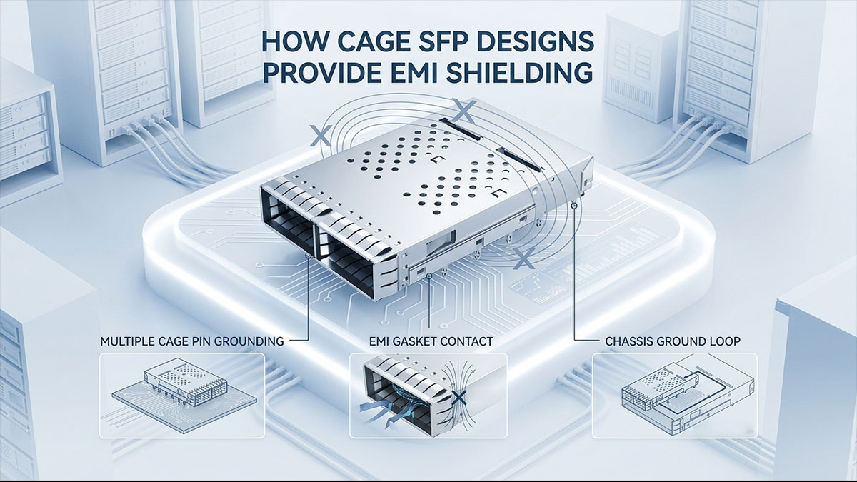
By integrating mechanical structure with electrical grounding paths, Cage SFP assemblies reduce both radiated and conducted EMI. This ensures stable optical module performance even in environments with significant electromagnetic activity.
Shielding Principles Behind Metal Cage Construction
The fundamental shielding effectiveness of a Cage SFP is based on its ability to create a continuous conductive barrier that redirects electromagnetic energy away from sensitive circuitry. The metal cage works in conjunction with the PCB ground plane to form a low-impedance path for unwanted currents.
This shielding mechanism relies on tightly controlled electrical and mechanical continuity.
Key principles include:
- Reflection of electromagnetic waves at conductive boundaries
- Absorption and dissipation of residual electromagnetic energy
- Ground continuity between cage structure and PCB reference plane
- Reduction of loop areas that can pick up or radiate noise
These principles work together to minimize electromagnetic coupling between the transceiver module and surrounding electronic components. The result is improved signal stability, especially in high-speed environments where even minor interference can affect performance.
The effectiveness of this shielding depends heavily on material conductivity, contact quality, and mechanical precision of the cage assembly.
Key EMI Shielding Features in Modern Cage SFP Designs
Modern Cage SFP structures incorporate multiple engineered features specifically designed to enhance electromagnetic compatibility and reduce noise leakage. These features ensure consistent shielding performance across different operating conditions and equipment layouts.
Typical EMI-focused design elements include:
- Spring finger contacts ensuring continuous grounding connection
- Conductive metal housing materials with high shielding efficiency
- Multi-point grounding structures for lower impedance paths
- EMI gaskets to reduce leakage at mechanical junctions
- Precision-cut cage apertures optimized for minimal emission escape
Each of these elements plays a distinct role in strengthening the overall shielding system. For example, spring fingers maintain stable electrical contact even under repeated module insertion cycles, while multi-point grounding reduces localized impedance variations that can weaken EMI suppression.
Shielding Effectiveness Across Different Network Environments
The performance of Cage SFP shielding varies depending on deployment conditions, particularly in environments with differing levels of electromagnetic activity and port density. High-performance designs are optimized to maintain consistent EMI suppression across these varied scenarios.
Shielding requirements typically differ across environments such as:
- Enterprise networks with moderate electromagnetic noise
- Data centers with high-density switch configurations
- Telecom systems exposed to long-distance signal aggregation
- Industrial environments with heavy electrical machinery interference
In each case, the Cage SFP must maintain stable grounding and effective electromagnetic containment despite changes in external noise levels and internal thermal conditions. High-density data center deployments, for example, require stronger shielding due to close proximity between active ports, while industrial environments demand higher resistance to external EMI sources.
These differences highlight the importance of adaptable shielding performance in ensuring consistent optical transceiver operation across diverse real-world applications.
? Thermal Challenges in SFP and SFP+ Deployments
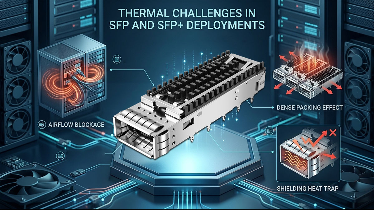
Thermal management has become a critical design constraint in SFP and SFP+ deployments due to continuously increasing data rates, higher port densities, and rising power consumption per transceiver. As optical modules operate at faster speeds, they generate more heat within a compact physical footprint, making temperature control essential for maintaining stable performance and long-term reliability. In dense switching environments, even small thermal inefficiencies can accumulate, leading to elevated chassis temperatures and reduced system stability.
Why Heat Generation Is Increasing
The increase in thermal load in modern SFP and SFP+ systems is directly linked to the evolution of higher-speed networking standards and more complex internal signal processing requirements. As data throughput grows, so does the power required to drive optical and electrical components.
Key drivers of increased heat generation include:
- Higher signaling rates requiring more power-intensive circuitry
- Integrated signal processing and retiming functions inside modules
- Increased port density in compact switching platforms
- Continuous operation under full-duplex traffic conditions
These factors collectively increase the thermal density per rack unit, placing additional stress on system-level cooling mechanisms. In high-performance environments, thermal buildup is not uniform, often creating localized hotspots around densely populated SFP cages.
Common Sources of Heat in Optical Networking Equipment
Heat in SFP and SFP+ environments is generated not only by the optical module itself but also by surrounding electronic components and system architecture. Understanding these sources is essential for effective thermal design and Cage SFP optimization.
Primary heat contributors include:
- Laser drivers and optical transmit components
- DSP and signal conditioning circuits inside the module
- Power regulation components on the host PCB
- Adjacent high-speed transceivers operating in close proximity
Each of these components contributes to the overall thermal load within the port region. In densely populated switch front panels, heat accumulation can become particularly pronounced due to limited spacing between cages, reducing natural convection efficiency.
These localized thermal effects make it necessary for Cage SFP structures to play an indirect but important role in guiding airflow and supporting heat dissipation pathways.
Impact of Excessive Temperatures on Performance
When thermal levels exceed optimal operating ranges, SFP and SFP+ modules may experience a range of performance degradation issues that directly affect network reliability and data integrity. These effects are often progressive and may worsen over sustained high-load operation.
Common thermal-related performance impacts include:
- Reduced optical signal efficiency and output power stability
- Increased bit error rates due to temperature-induced signal drift
- Accelerated aging of semiconductor and laser components
- Activation of thermal throttling mechanisms in advanced modules
In severe cases, excessive heat can also trigger automatic link degradation or temporary shutdowns to protect hardware integrity. This not only affects individual port performance but can also impact overall system throughput in high-density deployments.
Effective thermal management is therefore essential to ensure that SFP and SFP+ systems maintain consistent performance under continuous high-bandwidth workloads, especially in environments where Cage SFP assemblies are tightly packed and airflow is constrained.
? The Role of Cage SFP in Thermal Shielding and Heat Management
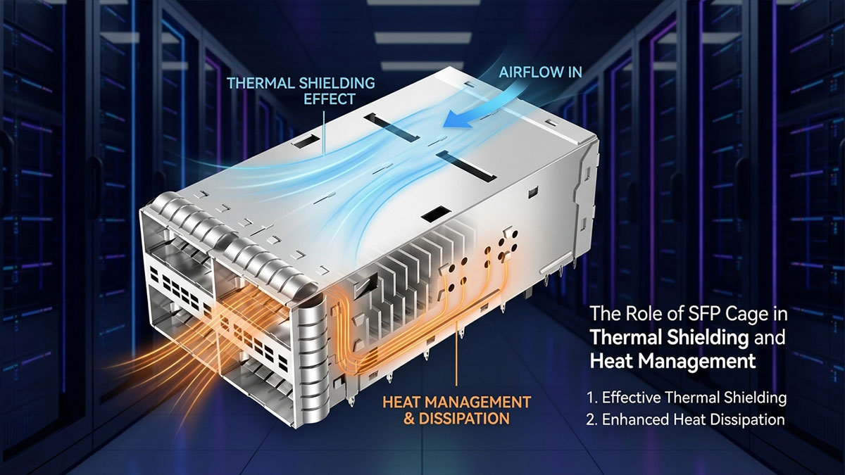
Cage SFP structures contribute to thermal performance by shaping airflow, facilitating heat conduction pathways, and stabilizing temperature distribution around high-density transceiver interfaces. Although they are primarily designed for mechanical support and EMI control, their metal construction and placement directly influence how heat is transferred and dissipated in SFP and SFP+ deployments. In compact networking equipment, these thermal effects become increasingly important as port density rises and cooling margins shrink.
Heat Transfer Mechanisms Within Cage SFP Assemblies
The thermal performance of Cage SFP assemblies is determined by multiple heat transfer mechanisms that operate simultaneously within a confined high-density environment. Each mechanism contributes differently to how heat is distributed, transferred, and ultimately removed from the transceiver region.
In practical deployments, these mechanisms do not work in isolation but interact with chassis airflow and metal cage structures to stabilize overall system temperature.
| Heat Transfer Mechanism |
Operating Principle |
Role in Cage SFP System |
Effectiveness in High-Density Environments |
| Conduction |
Heat transfer through direct contact between materials |
Moves heat from SFP module into metal cage and PCB ground structure |
High, especially when metal cage contact is optimized |
| Convection |
Heat transfer through air movement |
Removes heat from cage surface via chassis airflow |
Medium to High, depends on airflow design and port spacing |
| Thermal Spreading |
Distribution of heat across conductive metal surfaces |
Reduces localized hotspots around individual SFP slots |
High in well-designed metal cage structures |
| Radiation |
Emission of heat energy from surfaces |
Minor contribution in enclosed chassis environments |
Low, usually negligible compared to conduction and convection |
These mechanisms collectively determine how effectively Cage SFP structures can stabilize temperature distribution across densely populated optical ports.
Metal Cage Design as a Thermal Management Element
The metal construction of Cage SFP assemblies plays a significant role in thermal stabilization due to its ability to distribute and balance heat across a wider surface area. While not an active cooling component, the cage structure functions as a thermal intermediary between the transceiver module and the system chassis.
Key thermal contributions of metal cage design include:
- Heat spreading across conductive metal surfaces
- Stabilization of localized temperature peaks near high-power modules
- Improved thermal coupling between cage and grounded PCB layers
- Reduction of thermal resistance at the module interface region
These characteristics help prevent the formation of extreme temperature gradients within densely populated port clusters. In high-speed networking systems, even minor temperature imbalances can affect optical performance, making this passive thermal regulation particularly valuable.
Airflow Optimization Around SFP Ports
Airflow management is a critical factor in maintaining stable thermal conditions in SFP and SFP+ deployments, especially in high-density switching platforms. Cage SFP structures influence airflow patterns by defining the physical geometry through which cooling air must pass.
In well-optimized systems, airflow is guided to maximize heat removal efficiency across all active ports.
Key airflow-related considerations include:
- Front-to-back airflow alignment in switch chassis design
- Adequate spacing between adjacent SFP cages for reduced airflow blockage
- Ventilation openings in cage structures to support convective cooling
- Coordination with system-level fan placement and pressure zones
When these factors are properly aligned, Cage SFP assemblies help create predictable airflow channels that improve overall cooling performance. However, in poorly designed layouts, airflow obstruction can lead to heat accumulation and localized hotspots.
? Design Features That Enhance EMI and Thermal Shielding Performance
Cage SFP performance in EMI suppression and thermal control is largely determined by its structural design and material engineering. In high-speed networking systems, even small variations in cage geometry, grounding quality, or material selection can significantly impact signal integrity and heat dissipation. As a result, modern Cage SFP designs integrate multiple optimized features that work together to improve electromagnetic containment and thermal stability under dense operational conditions.
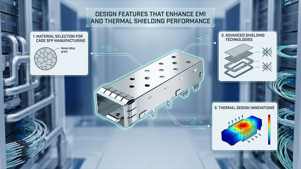
These enhancements are not isolated improvements but part of a coordinated design approach that balances electrical performance, mechanical durability, and thermal efficiency.
Material Selection for Cage SFP Manufacturing
Material choice is one of the most important factors influencing both EMI shielding effectiveness and thermal behavior. The conductivity, durability, and surface treatment of cage materials directly affect how well electromagnetic energy is contained and how efficiently heat is distributed.
Common material characteristics include:
- High electrical conductivity for effective EMI reflection and grounding
- Mechanical rigidity to maintain structural stability under repeated insertion cycles
- Corrosion resistance for long-term operational reliability
- Surface plating for improved contact performance and oxidation protection
Typical engineering materials used in Cage SFP construction include stainless steel and nickel-plated alloys, both of which provide a balance between shielding efficiency and mechanical strength. In high-density systems, material selection also influences thermal spreading behavior, as more conductive materials help distribute heat more evenly across the chassis interface.
Advanced Shielding Technologies
Modern Cage SFP designs incorporate advanced electromagnetic control mechanisms that go beyond basic metal enclosure functionality. These enhancements are focused on improving grounding continuity, reducing leakage paths, and minimizing interference in densely packed port environments.
Key shielding technologies include:
- Multi-point grounding structures that reduce impedance and improve EMI drainage
- Precision-engineered spring finger contacts ensuring stable electrical continuity
- Optimized cage geometry to minimize electromagnetic leakage gaps
- Integrated EMI suppression features at mechanical seams and junctions
Each of these technologies enhances the cage’s ability to contain high-frequency noise generated by nearby transceivers and PCB traces. Multi-point grounding is particularly important in high-speed systems, as it prevents localized grounding failures that can weaken overall shielding performance.
Thermal Design Innovations
Thermal performance in Cage SFP systems is increasingly influenced by structural innovations that enhance heat dissipation and airflow efficiency. As network equipment continues to scale toward higher port counts and faster transmission speeds, thermal constraints have become a central design consideration.
Key thermal design innovations include:
- Vented cage structures that promote controlled airflow through port regions
- Optimized cage geometries designed to reduce airflow obstruction
- Heat-spreading metal layouts that improve thermal distribution across surfaces
- Enhanced integration with chassis-level cooling systems for better heat extraction
These innovations help reduce localized thermal buildup, particularly in high-density switch front panels where airflow is often restricted. Ventilation patterns within the cage are carefully engineered to balance EMI shielding requirements with thermal airflow needs, ensuring that neither function compromises the other.
? Best Practices for Maximizing Cage SFP Shielding Performance
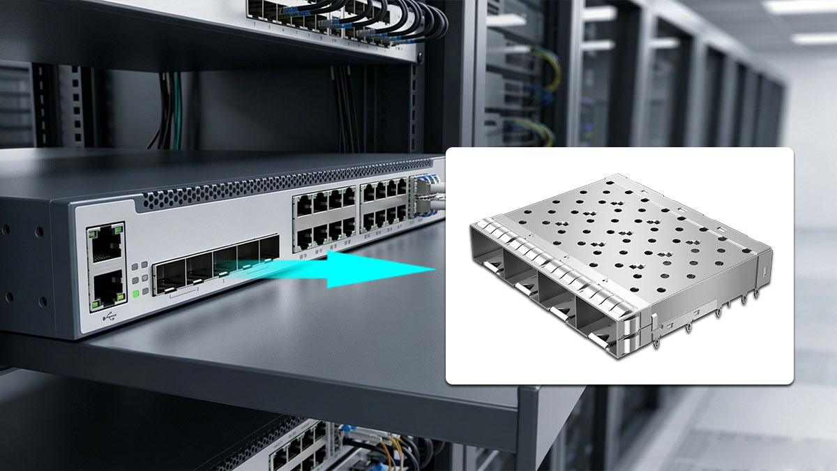
Maximizing Cage SFP shielding performance requires coordinated attention to electrical grounding, PCB layout, mechanical installation, and system airflow design. In high-speed networking environments, EMI control and thermal stability are tightly interconnected, meaning that small design or deployment decisions can significantly influence signal integrity and long-term reliability. Proper implementation ensures that Cage SFP assemblies perform consistently under dense port configurations and high traffic loads.
PCB and System-Level Design Considerations
Effective Cage SFP performance begins at the PCB level, where grounding structure, signal routing, and connector placement directly determine EMI behavior. Poor board design can weaken even well-engineered cage structures, while optimized layouts enhance their shielding effectiveness.
Key PCB and system-level considerations include:
- Solid ground plane integration beneath SFP cage regions
- Short and controlled signal trace routing to reduce loop areas
- Proper via stitching around cage mounting points for grounding continuity
- Strategic placement of high-speed lanes away from noisy power circuits
These design practices help minimize electromagnetic coupling and ensure stable reference grounding between the cage and the PCB. Via stitching, in particular, strengthens the connection between the cage and ground plane, reducing impedance and improving EMI containment across high-frequency signals.
Installation and Maintenance Recommendations
Proper installation and ongoing maintenance play a crucial role in preserving Cage SFP shielding and thermal performance over time. Even minor mechanical misalignment or contamination can degrade grounding contact quality and reduce EMI suppression effectiveness.
Important operational practices include:
- Ensuring correct alignment during SFP module insertion to maintain full cage contact
- Regular inspection of spring fingers and grounding points for wear or deformation
- Keeping connector areas free from dust and oxidation buildup
- Monitoring for signs of mechanical looseness in high-vibration environments
These steps help maintain stable electrical continuity between the cage and the transceiver module. In high-reliability systems, consistent maintenance is essential to prevent gradual degradation of shielding performance that may otherwise go unnoticed until signal issues appear.
Deployment Strategies for High-Density Environments
High-density networking environments place additional stress on both EMI containment and thermal management systems. As port counts increase, Cage SFP assemblies must operate in closer proximity, increasing the risk of electromagnetic coupling and airflow restriction.
Effective deployment strategies include:
- Optimizing port spacing to reduce electromagnetic and thermal interference between adjacent cages
- Designing front-to-back airflow paths to improve heat removal efficiency
- Grouping high-power modules strategically to balance thermal distribution
- Using chassis-level cooling systems that align with cage airflow patterns
These strategies help ensure that electromagnetic noise is contained within individual port regions while also maintaining efficient heat dissipation across the entire chassis. In dense switch architectures, airflow coordination is particularly important, as poorly managed cooling can amplify both thermal buildup and EMI susceptibility.
? Future Trends in Cage SFP EMI and Thermal Shielding
Cage SFP EMI and thermal shielding technologies are evolving alongside the continuous increase in network bandwidth, port density, and system integration complexity. As data rates move toward 25G, 50G, and beyond in compact form factors, electromagnetic control and thermal management are becoming more tightly coupled at both component and system levels. Future Cage SFP designs are expected to focus on higher efficiency shielding, improved heat dissipation pathways, and deeper integration with intelligent system monitoring.
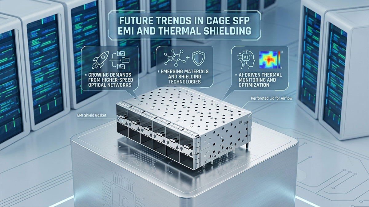
Growing Demands from Higher-Speed Optical Networks
The transition to higher-speed optical networking is placing significantly greater stress on Cage SFP structures, particularly in terms of EMI containment and thermal density management. As signaling frequencies increase, electromagnetic emissions become more complex and harder to isolate using conventional shielding techniques.
Key drivers shaping future requirements include:
- Increasing data rates that elevate high-frequency electromagnetic emissions
- Higher port density leading to stronger cross-port coupling effects
- Reduced noise margins in advanced optical modulation schemes
- Greater power consumption per transceiver in compact form factors
These conditions require Cage SFP systems to evolve from simple passive shielding structures into more optimized electromagnetic environments. At the same time, tighter thermal constraints demand improved heat spreading and airflow coordination at the cage level.
Emerging Materials and Shielding Technologies
Material science advancements are expected to play a central role in improving Cage SFP performance, particularly in environments where traditional metal cages face limitations in weight, conductivity balance, and thermal behavior. New shielding approaches are being developed to enhance both EMI attenuation and heat dissipation efficiency.
Key emerging technologies include:
- Advanced conductive coatings that improve surface-level EMI reflection
- Lightweight metal composites with enhanced thermal conductivity
- Multi-layer shielding structures for improved electromagnetic isolation
- Surface-engineered contact materials that reduce grounding resistance
These innovations aim to improve shielding performance without increasing mechanical complexity or reducing airflow efficiency. Enhanced material conductivity also contributes to better thermal spreading across cage surfaces, reducing localized hotspots in high-density configurations.
AI-Driven Thermal Monitoring and Optimization
Intelligent system management is becoming an increasingly important part of thermal control in high-density networking environments. Instead of relying solely on passive cooling and fixed airflow designs, future systems are expected to incorporate real-time monitoring and adaptive thermal optimization.
Key capabilities emerging in this area include:
- Real-time temperature monitoring at individual cage and port levels
- Predictive thermal modeling based on traffic load and power consumption
- Dynamic fan speed adjustment for optimized airflow distribution
- Automated detection of thermal hotspots across dense SFP arrays
These intelligent systems help maintain stable operating conditions by dynamically responding to changes in workload and environmental conditions. When combined with improved Cage SFP thermal designs, they enable more precise control over heat distribution and system cooling efficiency.
? Conclusion
Cage SFP plays a critical role in modern high-speed networking by combining mechanical support with effective EMI shielding and thermal management capabilities. Through its metal cage structure, grounding design, and airflow-influencing geometry, it helps maintain signal integrity and stable operating temperatures in SFP and SFP+ deployments. As network systems continue to scale in speed and density, the importance of integrated electromagnetic interference control and heat dissipation within Cage SFP designs becomes increasingly significant for long-term network reliability and performance.
The essential insights from Cage SFP EMI and thermal shielding design can be summarized as follows:
- Cage SFP structures provide both physical protection and electromagnetic containment for optical transceivers
- EMI shielding is achieved through grounded metal enclosures, spring contacts, and low-impedance electrical paths
- Thermal performance depends on heat conduction through the cage, airflow optimization, and system-level cooling design
- High-density deployments increase both EMI coupling risk and thermal load, requiring optimized cage architecture
- Material selection and precision manufacturing directly influence shielding effectiveness and thermal stability
These points highlight how Cage SFP design functions as a combined electrical and thermal control element within modern networking hardware rather than a standalone mechanical component.
As network infrastructure continues evolving toward higher bandwidth and greater port density, the role of Cage SFP in maintaining stable EMI performance and efficient thermal behavior becomes even more important. Selecting well-engineered cage solutions helps ensure consistent system performance in demanding environments where signal integrity and heat management are critical.
For high-quality optical interconnect components and engineered Cage SFP solutions designed for modern networking systems, further technical resources and product options are available through the LINK-PP Official Store.