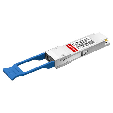
As 100G Ethernet deployments continue to scale across modern data centers, cloud networks, and metro interconnects, optical transceiver design has shifted toward higher efficiency and simpler architectures. One of the most important developments in this evolution is 100GBASE-LR1, a single-lambda 100G optical solution built for reliable transmission over single-mode fiber.
Unlike earlier 100G optics such as LR4, which rely on multiple wavelengths and complex optical multiplexing, LR1 transceivers transmit the full 100Gbps signal over a single 1310 nm wavelength using PAM4 modulation. This architectural change reduces optical complexity, lowers power consumption, and significantly improves scalability for high-density switching environments.
From a deployment perspective, 100GBASE-LR1 is primarily used in data center interconnect (DCI), leaf-spine architectures, and metro aggregation networks, where link distances typically extend up to 10 km over OS2 single-mode fiber. Its design also aligns with the broader industry shift toward single-lambda optics, which are becoming the foundation for QSFP28 100G, QSFP56 200G, and QSFP-DD 400G generations.
However, despite its growing adoption, LR1 is often misunderstood. Engineers and procurement teams frequently compare it with LR4, DR, and FR optics—especially when evaluating compatibility, cost efficiency, and future migration paths. Discussions in technical communities consistently highlight the same concerns: Will it interoperate? Is it truly standard? How does signal integrity hold over longer distances with PAM4?
This article breaks down those questions in a structured, engineering-focused way. You will learn how 100GBASE-LR1 maintains signal integrity over single-mode fiber, how it compares with other 100G optical formats, and how to choose the right transceiver for your network design without risking compatibility or performance issues.
By the end, you will have a clear, practical understanding of where LR1 fits in modern optical networks—and when it is the right choice for scalable, cost-efficient 100G deployments.
🟨 What Is 100GBASE-LR1?
100GBASE-LR1 is a type of 100 Gigabit Ethernet optical transceiver designed for transmission over single-mode fiber (SMF) using a single wavelength (lambda). In simple terms, it is a modern 100G optical solution that sends the full 100Gbps signal over one light channel instead of splitting it across multiple wavelengths.
At its core, LR1 represents a shift in optical design philosophy. Traditional 100G optical modules such as LR4 use four separate wavelengths (4×25G lanes), which require optical multiplexing and more complex internal components. In contrast, LR1 uses a single optical channel at approximately 1310 nm combined with PAM4 (Pulse Amplitude Modulation 4-level signaling) to achieve the full data rate over one lane. This is often referred to as a “single-lambda 100G architecture.”
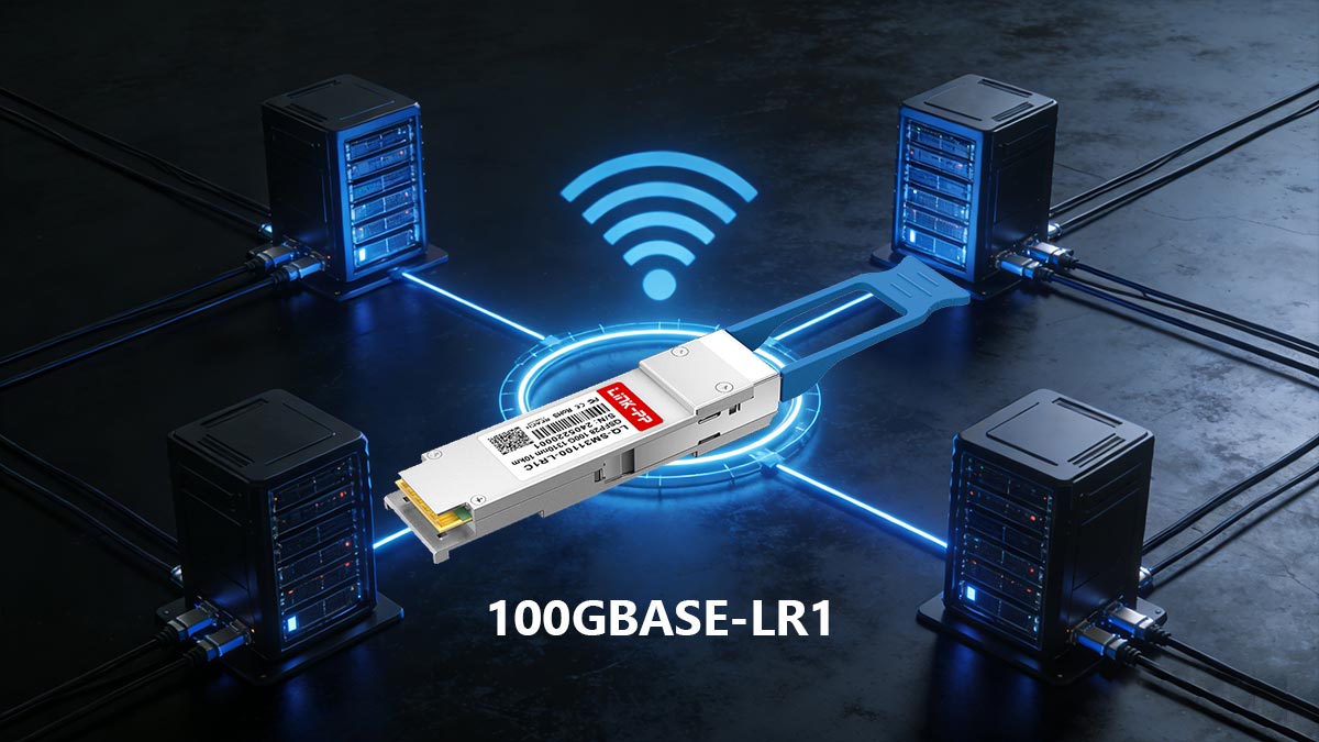
Simple Definition:
100GBASE-LR1 = A single-wavelength 100G Ethernet optical module for up to ~10 km over single-mode fiber using PAM4 modulation.
Key Characteristics of 100GBASE-LR1
- Single-lambda design (1×100G lane)
- 1310 nm wavelength operation
- PAM4 modulation (higher spectral efficiency than NRZ)
- Duplex LC interface over single-mode fiber (OS2)
- Typical reach: up to 10 km (with FEC depending on system design)
This simplified architecture reduces the number of optical components inside the module, which often results in:
- Lower power consumption
- Reduced cost compared to LR4
- Easier scalability for high-density switching platforms
All You Need to Know About 100GBASE-LR1
Queries around 100GBASE-LR1 come from a mix of technical, operational, and learning-focused audiences. Each group approaches the topic with different goals, but all are trying to solve practical questions related to deployment, compatibility, or understanding of modern 100G optical technology.
1. Network Engineers & Data Center Architects
This group is responsible for designing and scaling high-speed networks, particularly in cloud data centers and metro interconnect environments.
Their main focus includes:
- How LR1 fits into leaf-spine architectures and data center interconnect (DCI) designs
- Whether LR1 can realistically replace LR4 in new 100G deployments
- Understanding signal integrity, optical budget, and reach limitations over single-mode fiber (SMF)
For them, LR1 is evaluated as a design optimization option that impacts both performance and long-term scalability.
2. Procurement & IT Infrastructure Teams
This audience is driven by cost control, vendor strategy, and deployment risk management.
Their key concerns include:
- Cost comparison between 100GBASE-LR1 vs LR4 vs FR/DR optics
- Compatibility issues such as vendor coding, firmware restrictions, and switch support validation
- Whether LR1 can be safely deployed in multi-vendor or mixed optical environments
In practice, LR1 is often evaluated as a cost-efficient alternative, but only after confirming interoperability and platform support.
3. Technical Researchers & Learners
This group is focused on understanding how modern 100G Ethernet works at a conceptual level.
Their typical interests include:
- What single-lambda 100G architecture means
- How PAM4 modulation enables 100Gbps transmission over one wavelength
- How LR1 compares with other optical standards like LR4, DR, and FR
For this audience, LR1 is part of a broader effort to understand the evolution of Ethernet optics and high-speed signaling technologies.
Together, these perspectives show that 100GBASE-LR1 is not just a specification—it is a practical decision point in modern optical network design, procurement strategy, and next-generation Ethernet learning paths.
Why 100GBASE-LR1 Matters Today
LR1 is part of a broader industry transition toward simplified, high-efficiency optical networking. Instead of increasing complexity with more wavelengths, modern designs aim to:
- Reduce optical lane count
- Improve port density
- Lower energy per bit
- Prepare for smooth upgrades to 200G and 400G single-lambda technologies
This makes LR1 not just a replacement for older LR4 designs, but also a foundational step in next-generation Ethernet optics.
In the next section, we will explore how 100GBASE-LR1 maintains signal integrity over single-mode fiber, and why PAM4 and FEC play a critical role in ensuring stable long-distance transmission.
🟨 How 100GBASE-LR1 Maintains Signal Integrity Over Single-Mode Fiber
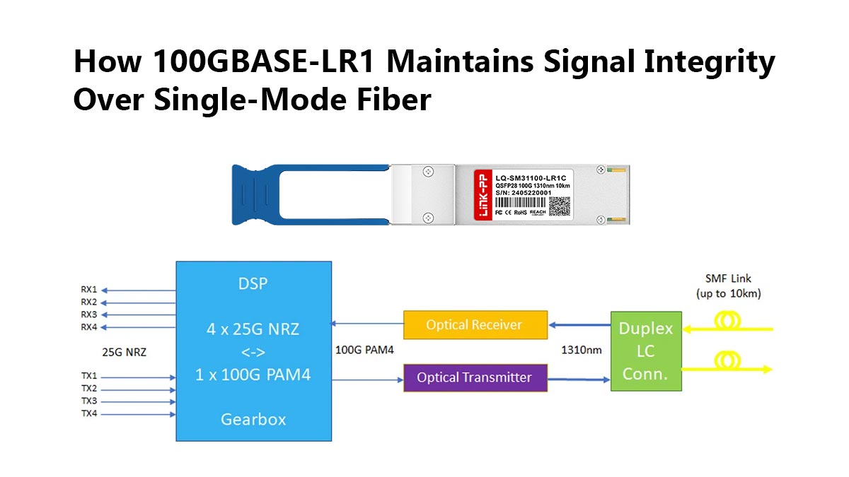
One of the most critical engineering challenges in 100GBASE-LR1 design is maintaining stable signal integrity over long-distance single-mode fiber (SMF) links. Unlike short-range optics, LR1 is designed for up to metro-scale distances (typically around 10 km), where attenuation, dispersion, and noise become significant factors.
To achieve reliable transmission, LR1 combines several key technologies: 1310 nm wavelength operation, PAM4 modulation, Forward Error Correction (FEC), and a carefully engineered optical power budget.
1. 1310 nm Wavelength Operation
100GBASE-LR1 operates at a 1310 nm wavelength, which sits in the optimal transmission window for single-mode fiber.
This wavelength is widely used because:
- It experiences low fiber attenuation over long distances
- It avoids severe chromatic dispersion issues found at other bands
- It provides a balance between reach and cost efficiency
Compared to shorter-wavelength optics (e.g., 850 nm used in multimode), 1310 nm is far better suited for stable long-distance 100G transmission over SMF.
2. PAM4 Signaling for Higher Efficiency
Unlike traditional NRZ (Non-Return-to-Zero) signaling used in older Ethernet generations, LR1 uses PAM4 (Pulse Amplitude Modulation with 4 signal levels).
PAM4 increases bits per symbol, enabling 100G over a single wavelength.
This means:
- Each symbol carries 2 bits instead of 1
- The signaling rate is reduced compared to NRZ for the same throughput
- Optical spectrum usage becomes more efficient
However, PAM4 also introduces:
- Smaller voltage margins between signal levels
- Higher sensitivity to noise and distortion
- Increased reliance on digital signal processing (DSP)
As a result, maintaining signal integrity becomes significantly more challenging than in older optical standards.
3. Forward Error Correction (FEC)
To compensate for PAM4’s increased error sensitivity, Forward Error Correction (FEC) is essential in LR1 systems.
FEC works by:
- Detecting and correcting bit errors at the receiver side
- Recovering data even when signal quality degrades
- Extending usable transmission distance without increasing optical power
In practical deployments, LR1 links are not designed to operate reliably without FEC, especially at longer distances near the upper limit of their reach.
4. Optical Budget Design
The optical budget defines the allowable loss between transmitter and receiver while still maintaining reliable communication.
Key contributors to loss include:
- Fiber attenuation (distance-based loss)
- Connector and splice losses
- Dispersion-related penalties
- Aging and environmental factors
For LR1, system designers carefully balance:
- Transmit optical power
- Receiver sensitivity
- Link margin for real-world conditions
A properly engineered optical budget ensures that the LR1 signal remains within a stable detection range even under worst-case deployment scenarios.
5. Why Signal Integrity Matters in Longer-Reach 100G Links
As data rates increase to 100G and beyond, signal integrity becomes the defining factor of network reliability.
In LR1 deployments, poor signal integrity can lead to:
- Increased bit error rates (BER)
- Link flapping or intermittent connectivity
- Reduced effective transmission distance
- Higher dependency on FEC correction cycles
This is especially important in:
- Data center interconnect (DCI) links
- Leaf-spine backbone connections
- Metro aggregation networks
Unlike short-reach optics where margins are generous, LR1 operates closer to the physical limits of high-speed PAM4 transmission. That makes careful engineering of wavelength stability, modulation quality, and optical power balance essential for consistent performance.
In the next section, we will compare 100GBASE-LR1 vs. LR4, focusing on architecture differences, cost implications, and real-world deployment decisions.
🟨 100GBASE-LR1 vs. LR4: What Is the Real Difference?
At first glance, 100GBASE-LR1 (like QSFP-100G-LR)and 100GBASE-LR4 may appear to deliver the same result—100Gbps Ethernet over single-mode fiber. However, their underlying architectures are fundamentally different, and those differences directly affect cost, compatibility, power consumption, and long-term scalability.
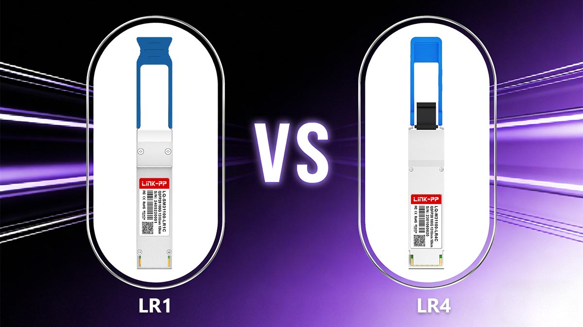
Understanding this comparison is essential for anyone designing or upgrading a 100G network.
▶ Wavelength Architecture: Single vs. Multi-Lane Design
The most important difference lies in how each standard achieves 100Gbps transmission.
100GBASE-LR4
LR4 uses a multi-lambda architecture:
- 4 wavelengths × 25Gbps each
- Each lane carries part of the total 100G signal
- Requires optical multiplexing/demultiplexing inside the module
100GBASE-LR1
LR1 uses a single-lambda architecture:
- 1 wavelength × 100Gbps
- Entire signal carried over one optical channel
- No optical wavelength splitting required
In simple terms:
LR4 = “4 lanes of traffic”
LR1 = “1 high-speed super lane”
▶ Modulation Technology: NRZ vs. PAM4
The modulation method is another key distinction.
LR4 uses NRZ (2-level signaling), while LR1 uses PAM4 (4-level signaling).
LR4 (NRZ)
- 1 bit per symbol
- More tolerant to noise
- Requires multiple wavelengths to reach 100G
LR1 (PAM4)
- 2 bits per symbol
- Higher spectral efficiency
- More sensitive to noise and requires DSP + FEC
Trade-off:
- LR4 = simpler signaling, more optical complexity
- LR1 = simpler optics, more electronic processing
▶ Reach and Transmission Distance
Both LR1 and LR4 are designed for long-reach 100G over single-mode fiber, but practical deployment characteristics differ.
| Standard | Typical Reach | Fiber Type |
|---|---|---|
| LR4 | Up to ~10 km | SMF |
| LR1 | Up to ~10 km (system-dependent) | SMF |
Key insight:
- LR4 has been widely deployed and proven over time
- LR1 achieves similar reach but relies more on DSP + FEC optimization
▶ Interoperability and Compatibility Risks
This is one of the most critical real-world differences.
LR4 interoperability
- Based on established multi-lane optical design
- Widely supported across legacy 100G platforms
- Generally stable in multi-vendor environments (with correct coding)
LR1 interoperability
- Requires PAM4-capable host support
- Not always supported on older line cards or switches
- More sensitive to vendor-specific implementation differences
Industry reality: Even if both are “100G LR”, LR1 and LR4 are not interchangeable.
This is a frequent source of deployment issues discussed in engineering communities, especially when mixing vendor optics or upgrading existing infrastructure.
▶ Cost, Power, and Procurement Impact
LR4 (older design)
- Higher optical component count (4 lasers)
- Higher manufacturing complexity
- Typically higher cost per module
- Mature but less efficient architecture
LR1 (newer design)
- Single laser design reduces optical complexity
- Lower power consumption per port
- Often more cost-efficient at scale
- Better aligned with next-gen high-density switching
Procurement insight:
- LR4 is often chosen for compatibility and legacy stability
- LR1 is preferred for new deployments and cost-optimized scaling
▶ Strategic Takeaway
The LR1 vs LR4 decision is not just technical—it is architectural.
- LR4 represents a mature, multi-lane optical era
- LR1 represents a shift toward single-lambda, DSP-driven Ethernet optics
In modern data center design, LR1 is increasingly favored for scalability and cost efficiency, while LR4 remains relevant in legacy or compatibility-constrained environments.
Next, we will explore how 100GBASE-LR1 compares with DR and FR optics, and how to choose the right solution for different link distances and architectures.
🟨 100GBASE-LR1 vs. DR vs. FR: Which Single-Lambda Optic Fits Your Link?
As 100G Ethernet moves toward single-lambda architectures, three key optical standards dominate modern deployments: 100GBASE-DR (like QSFP-100G-DR-S), 100GBASE-FR (like QSFP-100G-FR-S), and 100GBASE-LR1 (like QSFP-100G-LR-S). While they may appear similar because they all rely on high-speed PAM4 signaling over single-mode fiber, they are designed for very different transmission distances and network roles.
Choosing the right one is primarily about link distance, topology, and cost efficiency.
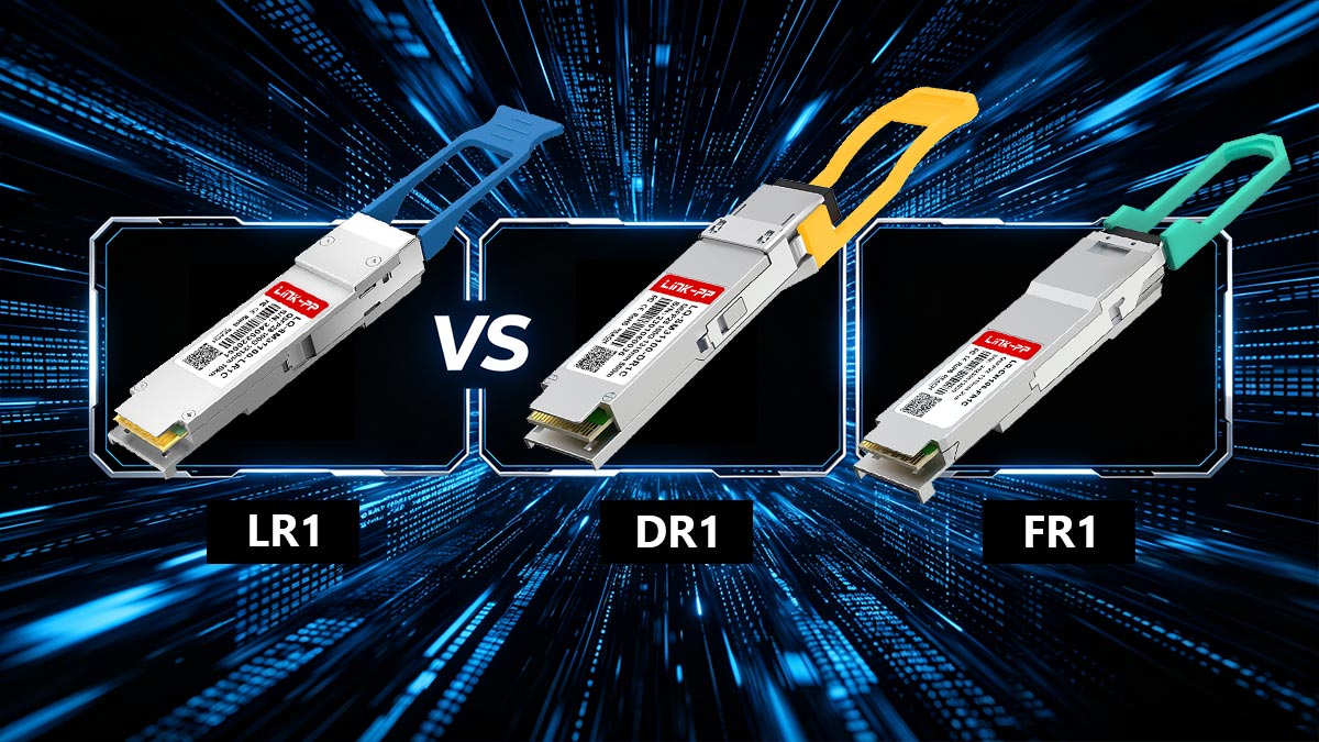
1. Quick Distance-Based Overview
The simplest way to understand the difference is by reach:
| Standard | Typical Reach | Use Case |
|---|---|---|
| 100GBASE-DR | ~500 m | Short-reach data center links |
| 100GBASE-FR | ~2 km | Data center interconnect within campus / metro edge |
| 100GBASE-LR1 | ~10 km | Metro DCI and longer campus networks |
This progression shows a clear design hierarchy: DR → FR → LR1 = increasing reach and link budget.
2. 100GBASE-DR: Short-Reach High-Density Links
DR (Data Center Reach) is designed for short-distance, high-density switching environments.
Key characteristics:
- ~500 meters over single-mode fiber
- Single 1310 nm wavelength
- PAM4 modulation
- Optimized for intra–data center leaf-spine connections
Typical use case:
- Rack-to-rack or pod-to-pod connections inside hyperscale data centers
DR is the most cost-efficient option per port but is limited in reach.
3. 100GBASE-FR: Mid-Range Data Center Interconnect
FR (Far Reach) extends the single-lambda concept further.
Key characteristics:
- ~2 km reach over SMF
- 1310 nm single-wavelength design
- PAM4 + DSP + FEC required
- Balanced between cost and distance
FR is designed for mid-reach 100G links where DR is insufficient but LR1 is over-provisioned.
Typical use case:
- Campus data centers
- Inter-building links
- Metro edge aggregation
FR is often considered the “sweet spot” for medium-distance 100G deployments.
4. 100GBASE-LR1: Long-Reach Single-Lambda Solution
LR1 is designed for long-distance, metro-scale connectivity.
Key characteristics:
- Up to ~10 km reach (depending on system design)
- Single 1310 nm wavelength
- PAM4 modulation with stronger DSP requirements
- Higher optical budget compared to DR and FR
Typical use case:
- Data center interconnect (DCI)
- Metro aggregation networks
- Cross-city or large campus backbone links
LR1 is the most scalable option in the single-lambda 100G family for longer reach scenarios.
5. How to Choose the Right 100G Optic
The decision is primarily driven by distance and architecture design, not just cost.
✔ Choose DR if:
- Your links are within a single data center
- Distance is under ~500 m
- You need maximum port density and lowest cost per connection
✔ Choose FR if:
- Your links extend up to ~2 km
- You are connecting buildings or nearby facilities
- You want a balance between cost and reach
✔ Choose LR1 if:
- Your links approach ~10 km
- You are building metro or DCI networks
- You need future-proof single-lambda architecture
6. Strategic Insight: Why Single-Lambda Matters
DR, FR, and LR1 all share one major industry trend: The shift from multi-lane optics to single-lambda PAM4-based Ethernet.
This shift brings:
- Lower optical complexity
- Higher port density
- Easier scaling toward 200G and 400G generations
- Reduced cost per bit over time
However, it also increases dependency on:
- DSP processing
- FEC correction
- Platform compatibility validation
Key Takeaway
- DR = shortest reach, highest density
- FR = balanced mid-range connectivity
- LR1 = long-reach, scalable metro and DCI solution
Rather than competing, these three standards form a distance-optimized optical toolkit for modern 100G networks.
Next, we will look at compatibility considerations for 100GBASE-LR1, including vendor coding, switch support, and real-world deployment risks.
🟨 Compatibility Checks Before You Deploy 100GBASE-LR1
Although 100GBASE-LR1 follows Ethernet standards and is widely adopted in modern data center designs, real-world deployments often fail not because of optical performance—but because of compatibility mismatches between optics, switches, and system configurations.
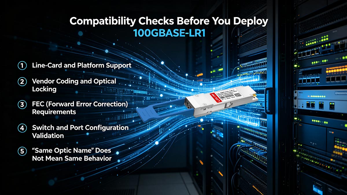
In practice, “100G LR1” is not always plug-and-play across all platforms. Proper validation is essential before deployment.
① Line-Card and Platform Support
The first and most critical check is whether the switch or router actually supports LR1 optics.
Even if a device supports 100G ports, it does not guarantee compatibility with all 100G optics types.
Key considerations:
- Some older 100G line cards only support LR4 or specific 100G QSFP28 profiles
- LR1 requires PAM4-capable hardware and DSP support
- Firmware or OS upgrades may be required for enablement
Important insight: Two devices with “100G QSFP28 ports” can still behave differently depending on ASIC generation and optical support matrix.
② Vendor Coding and Optical Locking
One of the most common deployment issues comes from vendor-specific transceiver coding.
Modern switches may:
- Accept only OEM-coded optics by default
- Reject third-party optical transceiver modules unless compatibility mode is enabled
- Require manual “allow unsupported transceiver” configuration
This means:
- A physically identical LR1 module may work on one platform
- But be blocked or flagged on another
Key takeaway: “Same standard” does not guarantee “same acceptance behavior” across vendors.
③ FEC (Forward Error Correction) Requirements
FEC is not optional for 100GBASE-LR1 in most real deployments.
Because LR1 uses PAM4 modulation, signal margins are tighter, making error correction essential.
FEC reduces bit error rate (BER) by correcting transmission errors at the receiver.
Why FEC matters:
- Improves link stability over longer distances
- Compensates for PAM4 signal sensitivity
- Enables operation close to optical power limits
Deployment risk:
If FEC is disabled or mismatched between endpoints:
- Link may fail to come up
- Or exhibit unstable performance under load
④ Switch and Port Configuration Validation
Even when hardware supports LR1, port configuration must match optical requirements.
Checklist includes:
- Correct port speed configuration (100G mode enabled)
- Matching FEC mode on both ends
- Proper transceiver type detection (QSFP28 LR1 profile)
- Ensuring no forced compatibility overrides are blocking negotiation
Common real-world issue: Ports configured for LR4 behavior may not correctly handle LR1 optics due to different electrical and optical expectations.
⑤ “Same Optic Name” Does Not Mean Same Behavior
One of the most misunderstood aspects of 100G optics is naming.
For example:
- “100G LR” may refer to LR4 in one vendor ecosystem
- The same label may refer to LR1 in another generation
- Some platforms treat LR1, LR4, and even FR as interchangeable in UI naming—but not in hardware behavior
Why this happens:
- Marketing names are not always strictly standardized across vendors
- Internal ASIC support defines actual behavior
- Optical lane architecture (single vs multi-lane) is fundamentally different
Critical insight:
Even if two transceiver modules are both labeled “100G LR”, they may:
- Use different modulation (PAM4 vs NRZ)
- Require different FEC profiles
- Be physically incompatible at the optical level
⑥ Deployment Best Practice Summary
Before deploying 100GBASE-LR1, always validate:
- ✔ Switch ASIC and line-card support matrix
- ✔ Vendor coding restrictions or unlock requirements
- ✔ FEC configuration consistency on both ends
- ✔ Correct port profile and optical mode
- ✔ True physical compatibility (not just naming similarity)
100GBASE-LR1 is a standards-based optical solution, but successful deployment depends heavily on platform compatibility and system-level configuration, not just the transceiver specification itself.
In modern networks, the biggest risk is not optical performance—it is assumed interoperability based on naming alone.
Next, we will conclude with a practical deployment guide and decision framework for choosing between LR1 and other 100G optical options in real-world networks.
🟨 Typical Use Cases for 100GBASE-LR1 in Data Centers and Campus Networks
With its single-lambda 100G design, ~10 km reach, and cost-efficient architecture, 100GBASE-LR1 fits a wide range of modern network scenarios. It is especially valuable where distance exceeds FR limits (2 km) but full DWDM or legacy LR4 complexity is unnecessary.
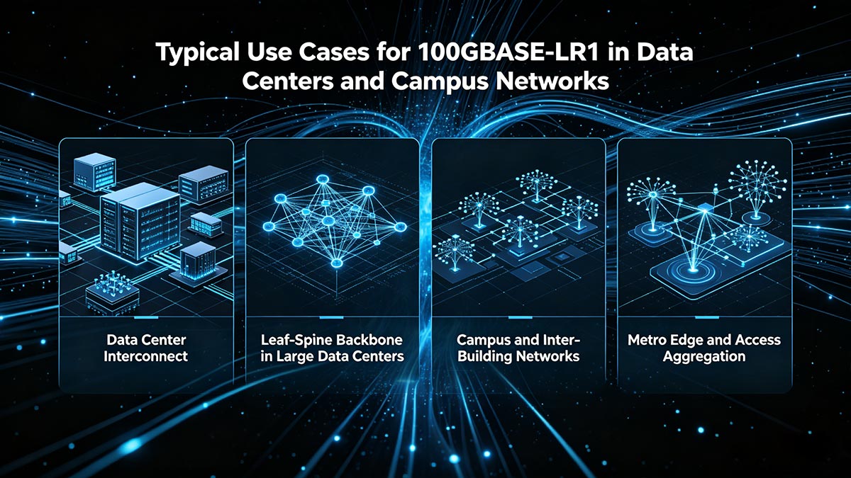
Below are the most common and practical deployment scenarios where LR1 delivers the strongest value.
♦ Data Center Interconnect (DCI)
One of the primary use cases for LR1 is data center interconnect.
Why LR1 works well:
- Supports up to ~10 km over single-mode fiber
- Eliminates the need for multi-wavelength LR4 optics
- Lower cost and power compared to legacy DCI solutions
Typical scenarios:
- Connecting two data centers within the same metro area
- Linking primary and backup sites
- High-bandwidth east-west traffic between facilities
LR1 provides a simplified, scalable alternative to LR4 for short-to-medium DCI links.
♦ Leaf-Spine Backbone in Large Data Centers
In large-scale data centers, not all links are short. Some spine-to-spine or cross-pod connections can extend beyond typical DR/FR distances.
Where LR1 fits:
- Long-distance leaf-to-spine or spine-to-spine links
- Cross-building or campus-scale data center fabrics
- High-density switching environments requiring fewer optical components per port
Key advantage:
- Maintains high port density while extending reach beyond 2 km
LR1 enables longer backbone links without changing architecture or adding complexity.
♦ Campus and Inter-Building Networks
Enterprise campuses and university networks often require reliable high-speed connectivity between buildings.
Why LR1 is ideal:
- Covers distances up to ~10 km without amplification
- Uses standard OS2 single-mode fiber infrastructure
- Avoids the cost of DWDM transceivers for moderate distances
Typical deployments:
- Core-to-distribution links across campus
- Inter-building aggregation
- High-capacity enterprise backbone connections
LR1 delivers carrier-grade performance without carrier-grade complexity.
♦ Metro Edge and Access Aggregation
At the edge of metro networks, operators need to aggregate traffic from multiple access points and deliver it to core networks.
LR1 advantages in metro edge:
- Handles longer aggregation links (beyond FR capability)
- Supports high-throughput 100G uplinks
- Reduces optical complexity compared to multi-lambda systems
Use cases:
- Aggregation switches to metro core
- ISP edge nodes
- 5G transport and fronthaul/backhaul support
LR1 is increasingly used as a cost-effective building block in metro-scale Ethernet networks.
♦ Migration from LR4 to Single-Lambda Architectures
A major driver for LR1 adoption is migration from legacy LR4 optics.
Why organizations migrate:
- Reduce cost per 100G port
- Lower power consumption
- Simplify optical architecture
- Align with future 200G / 400G single-lambda evolution
Migration considerations:
- Ensure platform support for PAM4 and FEC
- Validate interoperability before replacing LR4 links
- Plan phased upgrades in mixed environments
LR1 is not just a replacement—it is a forward-looking upgrade path toward next-generation Ethernet optics.
Key Takeaway: 100GBASE-LR1 fits best in environments where:
- Distance exceeds 2 km (FR limit) but stays within ~10 km
- High bandwidth and cost efficiency are both required
- Network design favors simpler, scalable single-lambda optics
From data center interconnects to campus backbones and metro edge networks, LR1 provides a balanced solution that combines reach, efficiency, and future-ready architecture—making it one of the most strategic 100G optical choices today.
🟨 Common Mistakes When Choosing 100GBASE-LR1
Despite its advantages, 100GBASE-LR1 is frequently misapplied in real deployments. Most issues don’t come from the optic itself—but from incorrect assumptions about compatibility, configuration, and link design. These are the exact pain points repeatedly seen in engineering forums and real-world projects.
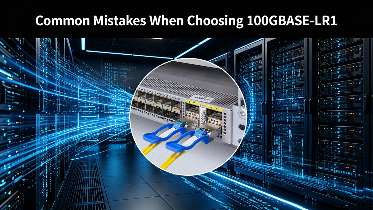
1. Mixing LR1 with LR4 and Expecting Interoperability
One of the most common mistakes is assuming that LR1 and LR4 can work together because they are both labeled “100G LR.”
The reality:
- LR1 = single wavelength (PAM4)
- LR4 = four wavelengths (NRZ)
- Completely different optical architectures
Result:
- Links will not establish
- No optical signal compatibility at the physical layer
Key takeaway: Matching speed (100G) does not mean matching technology.
2. Ignoring FEC Requirements
Another frequent issue is overlooking Forward Error Correction (FEC) settings.
Why this matters:
- LR1 relies on PAM4, which has tighter signal margins
- FEC is required to maintain acceptable bit error rate (BER)
Without FEC, PAM4 links experience significantly higher BER and instability.
What happens if ignored:
- Link may fail to come up
- Intermittent errors under load
- Reduced effective transmission distance
Best practice: Always verify that FEC is enabled and consistent on both ends of the link.
3. Assuming All 100G Optics Interoperate
Many users assume that any 100G QSFP28 module will work with another, regardless of type.
The misconception:
- “If both sides are 100G, they should connect”
The reality:
- Different standards (LR1, LR4, FR, DR) use:
- Different modulation schemes
- Different lane structures
- Different optical budgets
Result: Incompatible optics = no link or unstable performance.
Key takeaway: 100G is a speed class, not a guarantee of interoperability.
4. Buying Based on the Label Instead of the Link Budget
A subtle but critical mistake is selecting optics based on name or price, rather than actual link requirements.
Common example:
- Choosing LR1 for a short 100 m link (overkill)
- Choosing FR for a 5 km link (insufficient reach)
What should be evaluated instead:
- Fiber distance and type (SMF vs. MMF)
- Total link loss (connectors, splices)
- Required margin for stability
- Environmental and aging factors
The correct approach: Design around the optical budget, not the marketing label.
5. Overlooking Platform and Vendor Compatibility
Even when the optic itself is correct, compatibility issues can arise from:
- Switch firmware limitations
- Vendor coding restrictions
- Lack of LR1 support on older hardware
Real-world outcome:
- Optic not recognized
- Port disabled or error state
- Manual overrides required
Best practice: Always confirm compatibility with:
- Switch vendor support matrix
- Tested third-party modules (if applicable)
6. Skipping Real-World Testing Before Deployment
Another overlooked step is failing to validate LR1 links in a controlled environment before production rollout.
Risks:
- Unexpected FEC mismatch
- Signal degradation under load
- Vendor-specific behavior differences
Recommendation:
- Test LR1 links in staging
- Verify stability, BER, and monitoring metrics
- Confirm interoperability before scaling
Most 100GBASE-LR1 deployment issues come down to assumptions, not technology.
Avoid these common mistakes:
- ❌ Mixing LR1 and LR4
- ❌ Ignoring FEC requirements
- ❌ Assuming all 100G optics are compatible
- ❌ Choosing optics based on name instead of link budget
By focusing on architecture, compatibility, and real link conditions, you can fully leverage LR1’s advantages—without running into the costly pitfalls that many teams encounter during deployment.
🟨 FAQ: 100GBASE-LR1 Basics, Wavelength, Ethernet Rate, and Reach
- Wavelength: ~1310 nm
- Speed: 100 Gbps
- Reach: Up to ~10 km
- Fiber: Single-mode (OS2)
- Connector: Duplex LC
- Modulation: PAM4
- FEC: Required
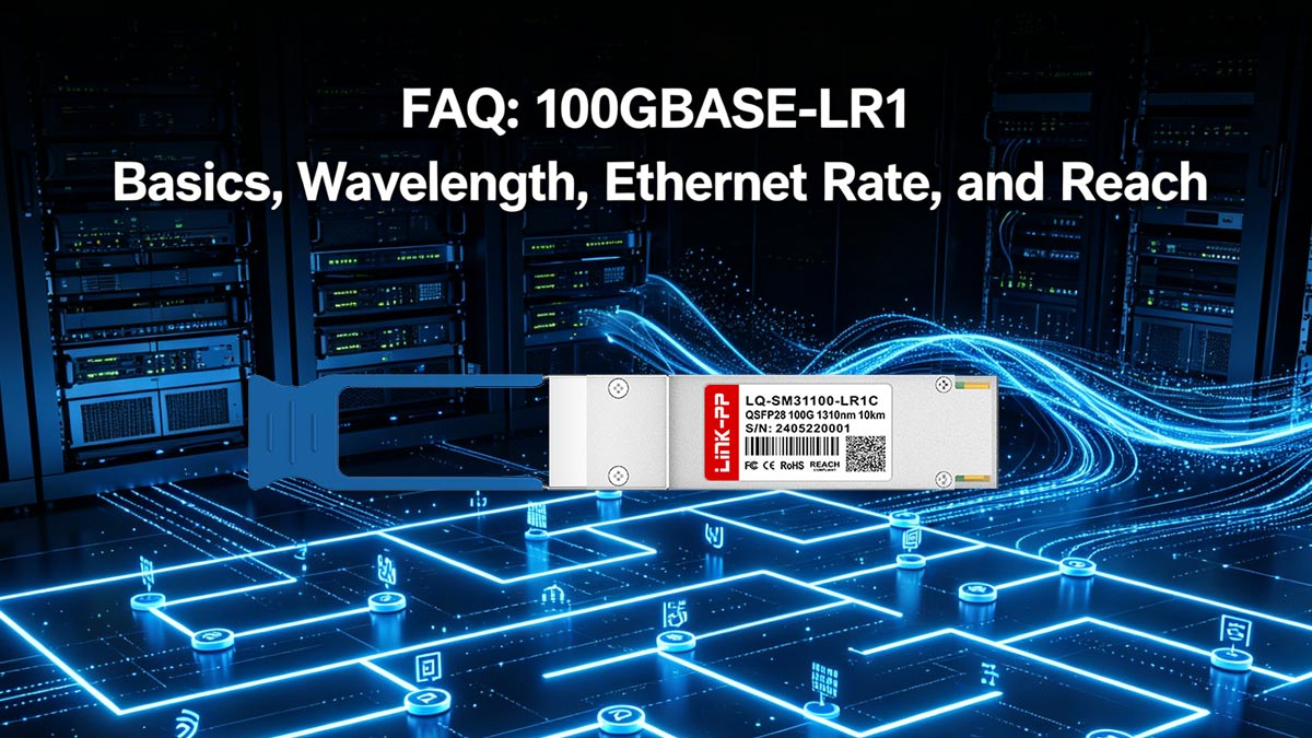
❓ What is the wavelength of 100GBASE-LR1?
100GBASE-LR1 operates at a central wavelength of approximately 1310 nm. This wavelength is optimized for single-mode fiber (SMF), offering low attenuation and stable performance over longer distances.
❓ What is the 100G Ethernet rate?
100G Ethernet (100GbE) delivers a data rate of 100 gigabits per second (100 Gbps). In LR1, this is achieved using PAM4 modulation, which transmits 2 bits per symbol over a single optical lane.
❓ What is the typical reach of 100GBASE-LR1?
100GBASE-LR1 typically supports transmission distances of up to 10 km over single-mode fiber (OS2). Actual reach may vary depending on:
- Link loss (connectors, splices)
- FEC implementation
- System design and margin
❓ Is 100GBASE-LR1 an IEEE standard?
Yes. 100GBASE-LR1 is defined under the IEEE 802.3 standard for 100G Ethernet. It is part of the industry transition toward single-lambda 100G optics using PAM4 signaling.
❓ What type of connector does 100GBASE-LR1 use?
Most 100GBASE-LR1 transceivers use a duplex LC connector. This allows transmission and reception over two fibers (Tx/Rx) in standard single-mode cabling systems.
❓ What type of fiber is required for 100GBASE-LR1?
100GBASE-LR1 requires single-mode fiber (SMF), typically OS2. Multimode fiber (MMF) is not supported due to distance and wavelength limitations.
❓ Does 100GBASE-LR1 require FEC?
Yes, Forward Error Correction (FEC) is typically required. Because LR1 uses PAM4 signaling, FEC is essential to:
- Maintain low bit error rates (BER)
- Ensure stable transmission over longer distances
❓ Is 100GBASE-LR1 suitable for data center use?
Yes. 100GBASE-LR1 is widely used in data centers, especially for:
- Data center interconnect (DCI)
- Campus backbone links
- Metro edge aggregation
It is best suited for distances beyond 2 km, where FR optics are insufficient.
🟨 How to Choose the Right 100GBASE-LR1 Modules
Selecting the right 100GBASE-LR1 transceiver is not just about matching a specification—it’s about ensuring reliable performance, full compatibility, and long-term scalability in your network.
Based on everything covered in this guide, the decision should follow a clear, practical evaluation path.
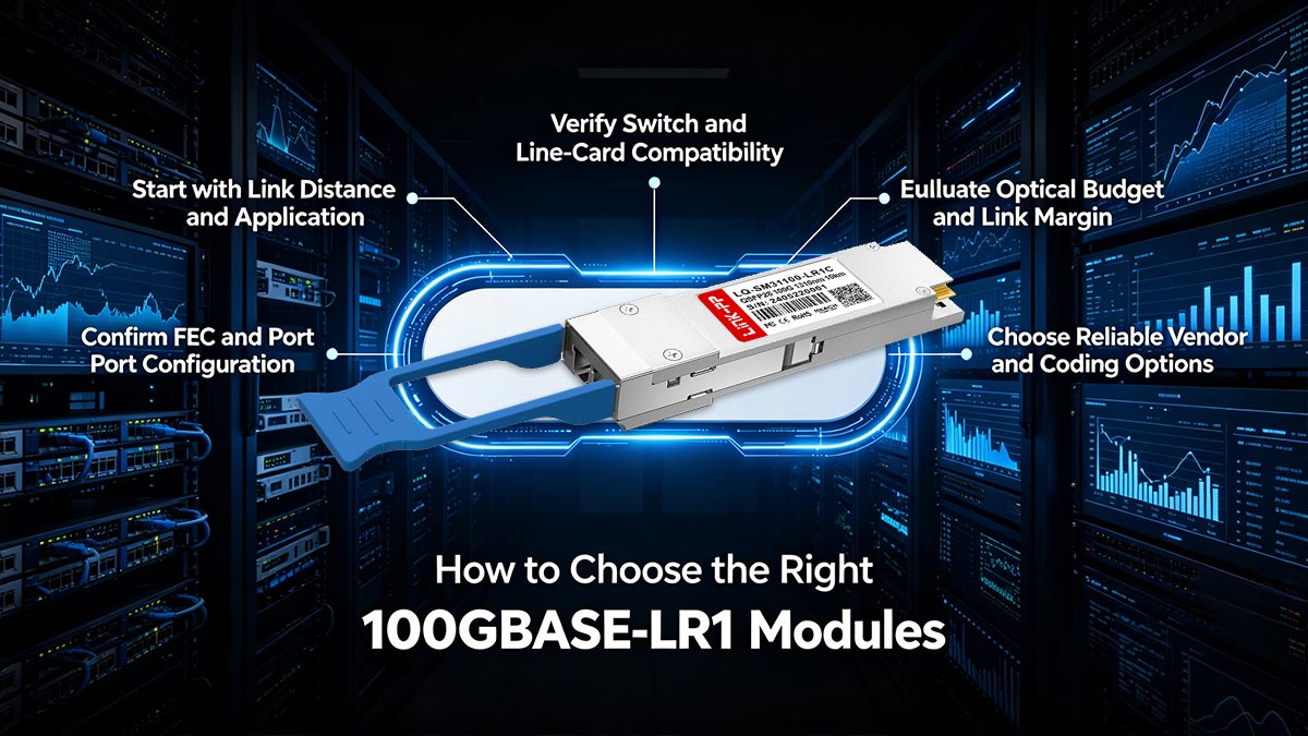
Start with Link Distance and Application
Before choosing any module, define your actual deployment scenario:
- Up to ~500 m → DR is more suitable
- Up to ~2 km → FR may be the better fit
- Up to ~10 km → LR1 is the right choice
If your link falls in the 2–10 km range, LR1 provides the best balance of reach, cost, and simplicity.
Verify Switch and Line-Card Compatibility
Always confirm that your equipment supports LR1:
- Check switch vendor compatibility lists
- Ensure the platform supports PAM4 and FEC
- Verify firmware/OS versions if required
This step prevents the most common issue: Buying a correct optic that the switch cannot use.
Confirm FEC and Port Configuration
Because LR1 depends on PAM4 signaling:
- Ensure FEC is enabled and matched on both ends
- Validate port settings for 100G LR1 operation
- Avoid mismatched configurations that can cause instability
Stable configuration = stable link.
Evaluate Optical Budget and Link Margin
Do not choose optics based only on labels.
Instead, calculate:
- Total fiber distance
- Connector and splice loss
- Required safety margin
LR1 should be selected when the optical budget aligns with real link conditions, not just theoretical reach.
Choose Reliable Vendor and Coding Options
To avoid interoperability risks:
- Use modules with verified compatibility coding
- Consider suppliers that support multi-vendor environments
- Ensure quality control and testing standards
This is especially important in mixed networks or large-scale deployments.
Plan for Future Scalability
LR1 is part of the broader shift toward single-lambda optics.
Choosing LR1 today helps:
- Align with 200G / 400G technology evolution
- Simplify future upgrades
- Maintain consistent architecture across generations
Final Recommendation
Choose 100GBASE-LR1 when you need:
- Reliable 10 km-class transmission over SMF
- Lower cost compared to LR4
- A future-ready, single-lambda architecture
Avoid it when:
- Your platform does not support PAM4/FEC
- Your link distance is significantly shorter (DR/FR is more cost-effective)
Ready to Deploy the Right 100GBASE-LR1 Solution?
If you're planning a deployment or upgrading your existing network, selecting the right transceiver partner is just as important as choosing the right standard.
Explore high-quality, compatibility-tested 100GBASE-LR1 modules at the LINK-PP Official Store, where you can find:
- Multi-vendor compatible solutions
- Cost-optimized optics for data centers and telecom
- Expert support for real-world deployment scenarios
Choosing the right module today ensures stable performance, lower costs, and a smoother path to future network upgrades.