
In modern network deployments, maintaining stable Ethernet connections is critical for both enterprise and small-scale environments. Mikrotik devices, widely used for their versatility and performance, can occasionally experience 100-meter link drops when connected via S RJ01 interfaces. These interruptions not only affect data throughput but can also lead to network instability, packet loss, and service disruptions. This guide explores the common causes of S RJ01 link drop issues, offers practical diagnostic methods, and provides step-by-step solutions to ensure reliable connectivity across your network infrastructure.
? S RJ01 and Mikrotik Link Stability Fundamentals
S RJ01 link drop issues on Mikrotik devices typically stem from a combination of physical cabling limitations, connector quality, and interface settings. Understanding these fundamentals is essential for diagnosing and resolving 100m link problems effectively. In most cases, stabilizing the link requires addressing both the physical layer and device configuration simultaneously.
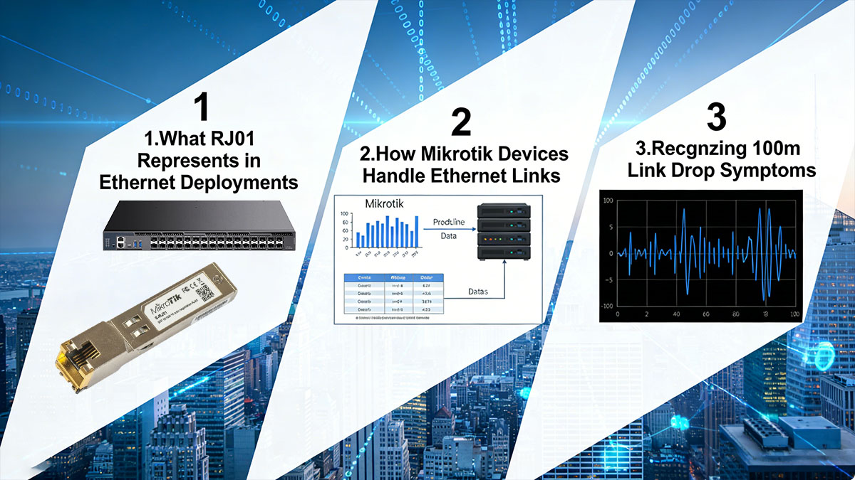
What S RJ01 Represents in Ethernet Deployments
S RJ01 interfaces are commonly used as the standard copper Ethernet connectors in Mikrotik networking equipment. Despite being similar in appearance to RJ45 connectors, the S RJ01 designation often refers to specific port types and wiring standards used in certain Mikrotik boards, particularly in industrial or high-density setups. These interfaces are designed to handle 10/100/1000 Mbps speeds over Cat5e or Cat6 cabling, including legacy Fast Ethernet copper transceivers such as GLC-FE-T and Gigabit copper SFP modules used in Mikrotik deployments, but their performance can degrade due to:
- Cable length approaching the 100-meter Ethernet limit
- Suboptimal cabling materials or installation practices
- External electromagnetic interference (EMI) from nearby equipment or power lines
Understanding the limitations and specifications of S RJ01 connectors allows network engineers to anticipate potential performance issues and implement preventive measures.
How Mikrotik Devices Handle Ethernet Links
Mikrotik devices rely on RouterOS to manage Ethernet links, including copper SFP transceivers such as GLC-T used for 1000BASE-T RJ45 connectivity. When a link is established, the interface negotiates the highest mutually supported speed between the device and the connected equipment. Key behaviors affecting link stability include:
- Auto-negotiation conflicts: mismatched settings can cause intermittent drops or speed fallback
- Physical layer error detection: Ethernet PHY chips continuously monitor packet errors and may reset links when error thresholds are exceeded
- Energy-efficient Ethernet features: some Mikrotik boards reduce power on idle links, which can inadvertently trigger link instability on marginal cabling
By understanding these behaviors, network administrators can differentiate between hardware limitations and configuration-induced link drops, ensuring faster troubleshooting.
Recognizing 100m Link Drop Symptoms
Link drops at or near 100 meters often follow a predictable pattern. Identifying these symptoms early can prevent prolonged network disruptions:
- Intermittent connectivity loss, often observed as “link flapping” in RouterOS interface logs
- Automatic speed reduction, e.g., from 1 Gbps down to 100 Mbps, indicating attenuation issues
- Increased packet loss or latency spikes during data-intensive operations
- Sporadic disconnects that are temporarily resolved by reconnecting cables or restarting the interface
Monitoring tools within Mikrotik, such as the interface status panel and Torch, provide real-time insight into these symptoms, allowing engineers to correlate physical cabling factors with observed network performance.
Understanding these fundamentals creates a solid baseline for tackling more complex link drop issues, as the root causes often lie at the intersection of cabling quality, connector integrity, and device configuration.
? Understanding the 100m Ethernet Limitation
Copper Ethernet links, including S RJ01 interfaces on Mikrotik devices, are fundamentally constrained by physical and electrical properties that limit reliable transmission to approximately 100 meters. Exceeding this distance introduces signal degradation, increased error rates, and link instability. Understanding the underlying causes is crucial for diagnosing S RJ01 link drops and designing resilient network infrastructure.
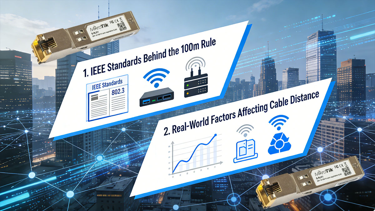
IEEE Standards and Physical Constraints
The 100-meter limitation originates from IEEE 802.3 standards, which define the maximum length for twisted-pair cabling at specified frequencies and speeds. Signal attenuation, crosstalk, and timing constraints impose strict boundaries:
- Signal attenuation: The voltage of the transmitted signal decreases over distance due to conductor resistance and dielectric losses. At 100 meters, the loss approaches the threshold that the receiver can reliably detect.
- Crosstalk (NEXT/FEXT): Electromagnetic coupling between adjacent twisted pairs introduces noise that accumulates with cable length, especially at higher frequencies required for Gigabit or faster Ethernet.
- Propagation delay and timing skew: Differences in wire length and pair impedance can cause bit misalignment at the receiver, which is critical for high-speed protocols.
These constraints explain why S RJ01 or standard RJ45 ports experience frequent link drops when deployed at or beyond the 100-meter threshold.
Real-World Factors Beyond Standards
Even when cabling meets IEEE specifications, real-world factors often exacerbate signal degradation:
- Environmental interference: Nearby power lines, motors, fluorescent lights, or industrial machinery generate electromagnetic interference that can induce errors.
- Temperature and humidity effects: Excessive heat or moisture can alter cable impedance and insulation resistance, affecting signal integrity.
- Cable quality variability: Differences in conductor gauge, twisting precision, or insulation materials affect attenuation and crosstalk.
- Connector and termination issues: Pin misalignment, corrosion, or poor crimping increases contact resistance, reducing the effective signal margin.
These factors collectively reduce the “practical” maximum distance below the theoretical 100 meters in many deployments.
Quantifying Link Limitations
A structured measurement approach highlights how speed, cable category, and environmental conditions interact:
| Cable Category |
Max Theoretical Distance |
Expected Practical Distance |
Typical Symptoms Near Limit |
| Cat5 |
100 m (100BASE-TX) |
90–95 m |
Intermittent drops, speed fallback |
| Cat5e |
100 m (1000BASE-T) |
85–100 m |
Packet errors, flapping links |
| Cat6 |
100 m (1000BASE-T) |
95–100 m |
Rare drops, mostly EMI-sensitive |
| Cat6a Shielded |
100 m+ (10GBASE-T) |
100 m+ |
Stable, even in high-EMI environments |
This table demonstrates that practical deployment distances often fall short of theoretical limits due to compounded real-world factors. For networks approaching these limits, it becomes essential to monitor link integrity and consider mitigation strategies such as higher-category cables, shielding, or intermediate switches.
? Common Causes of S RJ01 Mikrotik Link Drops
Link instability in S RJ01 connections is rarely caused by a single factor. Most 100-meter link drops result from the interplay of physical cabling constraints, connector integrity, device hardware, and interface configuration. Understanding these causes with precision allows engineers to apply targeted solutions and prevent recurring issues.
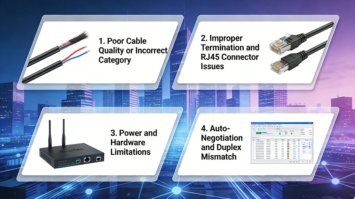
Poor Cable Quality or Incorrect Category
Even when cables meet minimum standards, variations in conductor size, twist consistency, or insulation can significantly impact signal integrity. Key issues include:
- Using cables below Cat5e for Gigabit links increases susceptibility to attenuation and crosstalk.
- Mixing cable categories along a single run (e.g., Cat5 + Cat6) causes impedance mismatches, leading to reflections and bit errors.
- Counterfeit or low-quality cables often fail standardized tests for insertion loss, NEXT, and return loss.
| Cable Category |
Max Supported Speed |
Typical Issue at 100 m |
Quantitative Indicators |
| Cat5 |
100 Mbps |
Link drops, reduced throughput |
Attenuation > 22 dB, NEXT < 35 dB |
| Cat5e |
1 Gbps |
Occasional packet errors |
Attenuation 20–22 dB, NEXT 35–40 dB |
| Cat6 |
1–10 Gbps |
Rare drops, EMI sensitive |
Attenuation < 20 dB, NEXT > 40 dB |
Regularly testing and certifying cables ensures that category compliance translates into practical reliability.
Improper Termination and S RJ01/RJ45 Connector Issues
High-quality cabling can fail without precise connector termination. Common issues:
- Loose or poorly crimped pins that increase contact resistance.
- Misaligned wire pairs that cause pair-to-pair crosstalk.
- Oxidation or corrosion on metal contacts, reducing signal voltage.
- Connector housing damage, which increases stress on individual conductors.
Quantitative symptom indicators include intermittent flapping, sudden speed reduction, or increasing CRC errors under moderate traffic.
Power and Hardware Limitations
Mikrotik devices rely on stable power and fully functional Ethernet PHYs to maintain link integrity:
- Insufficient voltage or unstable power supply can cause PHY chips to reset, triggering link drops.
- Degraded or aging Ethernet ports increase insertion loss and reduce tolerance to noise.
- Overheating due to environmental temperature or high port utilization can temporarily disable interfaces, particularly when using high-power 10G copper transceivers such as SFP-10G-T-X.
Monitoring device voltage, temperature, and interface logs helps identify whether hardware is contributing to instability.
Auto-Negotiation and Duplex Mismatch
Configuration conflicts remain a frequent cause of link drops, especially in mixed-vendor environments:
- Auto-negotiation failures between devices can cause frequent link resets or fallback to lower speeds.
- Duplex mismatches produce collisions and frame errors, leading to packet loss.
- Even correctly configured cables can underperform if one end is forced to an incompatible speed.
Recommended diagnostic steps:
- Verify interface logs for speed and duplex change events.
- Manually set speed/duplex when repeated auto-negotiation failures occur.
- Confirm performance using sustained traffic tests after adjustments.
? Diagnosing S RJ01 Link Drop Problems in Mikrotik
Accurately diagnosing link drops in S RJ01 interfaces requires a methodical approach that examines physical cabling, connectors, device hardware, and interface configuration. Combining RouterOS monitoring tools with targeted cable testing allows network engineers to pinpoint root causes and apply effective solutions.
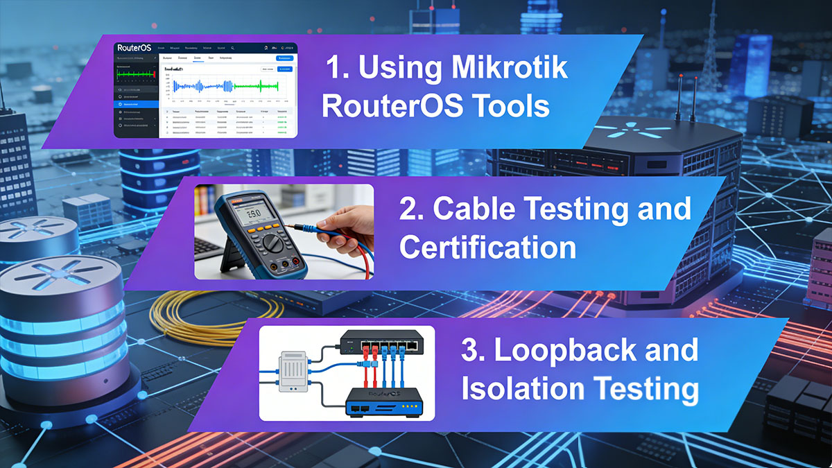
Using Mikrotik RouterOS Tools
Mikrotik RouterOS provides a suite of monitoring tools that enable detailed analysis of Ethernet interfaces:
- Interface Status Panel: Displays current speed, duplex mode, link state, and real-time traffic. Frequent state changes or speed fallbacks indicate instability.
- Error Counters: Observing RX/TX errors, CRC errors, collisions, and frame drops helps identify whether the problem originates from cabling, connectors, or device PHYs.
- Torch Tool: Provides per-port traffic analysis, revealing whether link drops coincide with high network load, specific protocols, or abnormal packet sizes.
| Monitoring Metric |
Normal Range |
Indicator of Potential Issue |
| RX/TX Errors |
0–5 per 1 million packets |
>50 indicates physical layer problems |
| Collisions |
0–2 per 1 million packets |
Frequent collisions suggest duplex mismatch |
| Link Flaps |
0 per day |
>2–3 per day suggests cabling or PHY issue |
Using these metrics, engineers can separate configuration-induced problems from hardware or cable-related causes.
Cable Testing and Certification
Physical cabling remains the most common source of link drops, particularly near 100 meters. Advanced cable testing provides quantitative insight:
- Continuity Test: Confirms wiring order and pair integrity.
- Attenuation Measurement: High attenuation (>22 dB for Cat5e at 100 MHz) indicates excessive signal loss.
- Crosstalk (NEXT/FEXT): Measures interference between pairs; values below 35 dB for Cat5e can trigger intermittent drops.
- Return Loss: Reflections above -20 dB can corrupt data frames.
Professional cable certifiers provide precise results that correlate directly with observed link drop symptoms.
Loopback and Isolation Testing
Isolating faulty components is critical in multi-segment networks. A systematic approach includes:
- Disconnecting intermediate switches or patch panels to test direct link performance.
- Replacing long runs with shorter, known-good cables to confirm whether distance contributes to drops.
- Performing loopback tests on the Mikrotik port to verify PHY functionality independently of external devices.
| Test Method |
Purpose |
Expected Outcome If Healthy |
| Short cable replacement |
Isolate cable vs. hardware |
Stable link confirms long cable issue |
| Loopback adapter test |
Test port/PHY independently |
No errors indicate port integrity |
| Segment isolation |
Remove intermediate devices |
Flawless link confirms problem in intermediate hardware |
This structured approach allows engineers to methodically identify whether the root cause is physical cabling, connectors, Mikrotik hardware, or configuration mismatch.
? Practical Solutions to Fix 100m Link Drop Issues
Resolving S RJ01 link drops on Mikrotik devices requires a combination of cabling improvements, connector maintenance, and interface configuration adjustments. Applying these solutions systematically ensures long-term stability and minimizes recurrence of 100m link failures.
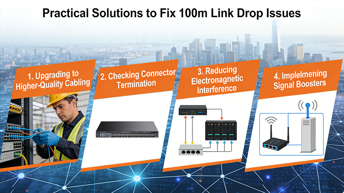
Upgrading to Higher-Quality Cabling
One of the most effective ways to prevent link drops is using cables that exceed minimum specifications. High-quality cabling reduces signal attenuation, crosstalk, and susceptibility to interference.
- Replace Cat5 or low-quality Cat5e cables with certified Cat6 or Cat6a cables for Gigabit and higher-speed deployments.
- Consider shielded twisted-pair (STP) cables in environments with strong electromagnetic interference (EMI).
- Verify cable labeling and certification to avoid counterfeit or substandard products.
| Cable Type |
Recommended Use Case |
Advantages for 100m Stability |
| Cat5e |
Standard office LAN |
Cost-effective for <1 Gbps |
| Cat6 |
Data centers or high-speed LAN |
Reduced crosstalk, supports 1–10 Gbps |
| Cat6a STP |
Industrial or EMI-prone areas |
Maximum interference protection, stable links |
Upgrading cabling alone often resolves the majority of 100m link drop issues, especially when combined with proper installation practices.
Improving Cable Installation Practices
Even high-quality cables can fail if installed improperly. Correct routing and handling minimize physical stress and external interference.
- Route cables away from high-voltage lines, fluorescent lighting, or motors.
- Maintain recommended bend radius (typically four times the cable diameter) to prevent internal conductor damage.
- Avoid tight stapling or compressing cables in conduits.
- Label and organize cables to reduce unnecessary handling and movement.
Proper installation reduces attenuation and error rates, particularly over longer distances near the 100-meter limit.
Re-terminating Connectors and Ensuring Proper Crimping
Connector issues are a common cause of intermittent link drops. Re-terminating S RJ01 or RJ45 connectors with attention to detail can restore link stability.
- Follow standard wiring schemes (T568A or T568B) consistently on both ends.
- Use high-quality crimping tools to ensure solid contact without damaging wires.
- Inspect connectors for visible damage or pin misalignment.
- Test re-terminated cables before deployment to confirm continuity and low error rates.
These steps address one of the most common physical-layer issues, particularly in older networks or after cable movement.
Adjusting Mikrotik Interface Settings
Sometimes, link drops are caused by negotiation or configuration mismatches rather than physical faults. Adjusting interface settings can stabilize connections.
- Manually set speed and duplex to match the connected device when auto-negotiation is unreliable.
- Disable energy-efficient Ethernet features if power-saving causes intermittent disconnects.
- Regularly monitor interface logs to confirm stability after changes.
By combining physical improvements with configuration adjustments, even marginal installations near the 100-meter limit can achieve stable connectivity.
? When to Consider Alternatives to Copper Ethernet
While proper cabling, connectors, and configuration can stabilize S RJ01 connections, certain scenarios require moving beyond copper to ensure reliable network performance. Alternatives such as fiber optic links or Ethernet extenders can overcome the inherent physical limitations of copper module.

Using Fiber Optic Links for Long Distances
Fiber optic cables and 10G SFP+ optical uplinks are ideal when link distances exceed 100 meters or when environmental factors compromise copper stability. The benefits of fiber include:
- Extended distance capabilities: Fiber links can span several kilometers without signal degradation.
- Immunity to electromagnetic interference (EMI): Ideal for industrial environments or areas with heavy electrical noise.
- Higher bandwidth potential: Supports 10 Gbps and beyond, future-proofing the network.
| Fiber Type |
Max Distance |
Typical Use Case |
| Single-mode |
Up to 40 km |
Long-haul links, ISPs, metro networks |
| Multi-mode OM3 |
Up to 300 m |
Data centers, campus backbone |
| Multi-mode OM4 |
Up to 400 m |
High-performance LAN and backbone |
Deploying fiber may require Mikrotik devices with SFP ports supporting 1G SFP or higher-speed optical uplinks to interface with existing copper networks. While the initial cost is higher, fiber provides unmatched stability and scalability for long-distance applications.
Deploying Ethernet Extenders or Switches
When replacing copper cabling with fiber is not feasible, Ethernet extenders or intermediate switches can extend the reach of copper links beyond 100 meters:
- Mid-span switches: Placing a switch at intermediate points regenerates the signal, effectively increasing distance while maintaining performance.
- Ethernet extenders: Devices that amplify or condition the copper signal, extending reach up to several hundred meters depending on cable quality.
- Trade-offs: Extenders and switches add additional points of potential failure, slight latency, and higher management complexity.
These solutions are practical for retrofitting existing infrastructure where cabling replacement is impractical, though careful planning is required to avoid introducing instability.
? Preventive Measures for Long-Term Network Stability
Ensuring long-term stability in S RJ01 Mikrotik networks requires proactive maintenance, standardized practices, and thorough documentation. Preventive measures help avoid recurring 100-meter link drops and improve overall network reliability.

Regular Maintenance and Inspection
Scheduled inspections and maintenance reduce the risk of unexpected link failures. Key practices include:
- Periodic cable checks: Visually inspect S RJ01/RJ45 connectors, patch panels, and cable runs for damage, pin misalignment, or wear.
- Performance monitoring: Use Mikrotik RouterOS tools to track interface errors, flapping events, and throughput trends over time.
- Cleaning and environment control: Keep connectors free from dust and ensure cables are not exposed to extreme temperatures or moisture.
Regular maintenance allows early detection of marginal connections that could cause intermittent drops, especially near the 100-meter threshold.
Standardizing Network Components
Consistency in network components simplifies troubleshooting and enhances link stability:
- Cable categories: Use the same cable type (Cat5e, Cat6, or Cat6a) throughout the network to reduce mismatched performance.
- Connector quality: Standardize on high-quality S RJ01 or RJ45 connectors and tools to minimize termination errors.
- Vendor consistency: Using components from reputable manufacturers ensures predictable performance and reduces the risk of counterfeit or substandard products.
Standardization reduces variability that often causes subtle link issues in complex or large-scale deployments.
Documentation and Network Planning
Thorough documentation and forward-looking network design prevent avoidable instability:
- Cable maps and port labeling: Keep accurate records of cable routes, endpoints, and patch panel assignments.
- Capacity planning: Design network segments with distance limitations, future expansion, and redundancy in mind.
- Upgrade scheduling: Plan regular replacement cycles for aging cables and hardware to prevent performance degradation.
By combining proper documentation with strategic planning, network engineers can anticipate and mitigate potential link drop scenarios before they impact operations.
? FAQs About S RJ01 Mikrotik Link Drop Issues
Why does my Mikrotik S RJ01 link drop exactly at around 100 meters?
Ethernet signal attenuation and crosstalk naturally increase near the 100-meter limit, causing intermittent connectivity or automatic speed fallback.
Can I extend Ethernet beyond 100 meters without replacing cables?
Yes, using Ethernet extenders or mid-span switches can boost the signal, but long runs may introduce latency or additional failure points.
Does shielding always improve link stability?
Shielded cables help in environments with high electromagnetic interference, but in low-EMI settings, shielding offers minimal benefit.
How do I identify whether the issue is cable or hardware?
Test with a known-good shorter cable, inspect connectors, and monitor interface error counters; consistent drops on multiple cables usually indicate device hardware issues.
Is auto-negotiation safe to use on S RJ01 ports?
Auto-negotiation generally works, but if intermittent drops occur, manually configuring speed and duplex may provide more stable connections.
How often should I inspect and maintain S RJ01 connections?
A routine inspection every 6–12 months is recommended, with additional checks after environmental changes, heavy network traffic, or physical disturbance of cables.
? Conclusion
Maintaining stable S RJ01 links on Mikrotik devices requires a combination of proper cabling, correct connector termination, careful interface configuration, and proactive network maintenance. By understanding the 100-meter Ethernet limitations, diagnosing link drops with RouterOS tools, and implementing preventive strategies, network engineers can ensure reliable performance and minimize downtime. For scenarios where copper cabling cannot meet distance or environmental requirements, alternatives such as fiber optic links or Ethernet extenders provide scalable solutions.
For high-quality networking components and solutions compatible with Mikrotik devices, explore the options available at LINK-PP Official Store to support long-term network stability and performance.


