



































As networks continue to evolve, the demand for faster yet practical connectivity solutions has grown significantly. 10GbE RJ45 SFP modules have emerged as a convenient option, allowing organizations to achieve 10-Gigabit speeds while still using familiar copper cabling. This makes them especially appealing for environments where upgrading to fiber is either too costly or unnecessary. With their plug-and-play flexibility, 10GbE RJ45 SFP transceiver modules are increasingly being adopted in data centers, enterprise networks, and edge deployments.
However, achieving high speed is only part of the story. The performance of a 10GbE RJ45 SFP link is closely tied to how efficiently signals are transmitted and how much latency is introduced along the way. Because copper-based transmission behaves differently from fiber, factors like signal interference, cable quality, and module design can all impact results. This article explores these underlying principles in a straightforward way, helping you better understand how to optimize 10GbE RJ45 SFP performance in real-world scenarios.
🔵 Introduction to 10GbE RJ45 SFP Technology
10GbE RJ45 SFP technology combines the flexibility of Small Form-factor Pluggable (SFP) modules with the widespread use of copper Ethernet cabling. It enables 10-Gigabit Ethernet transmission over standard RJ45 interfaces, making it a practical choice for upgrading existing network infrastructures.
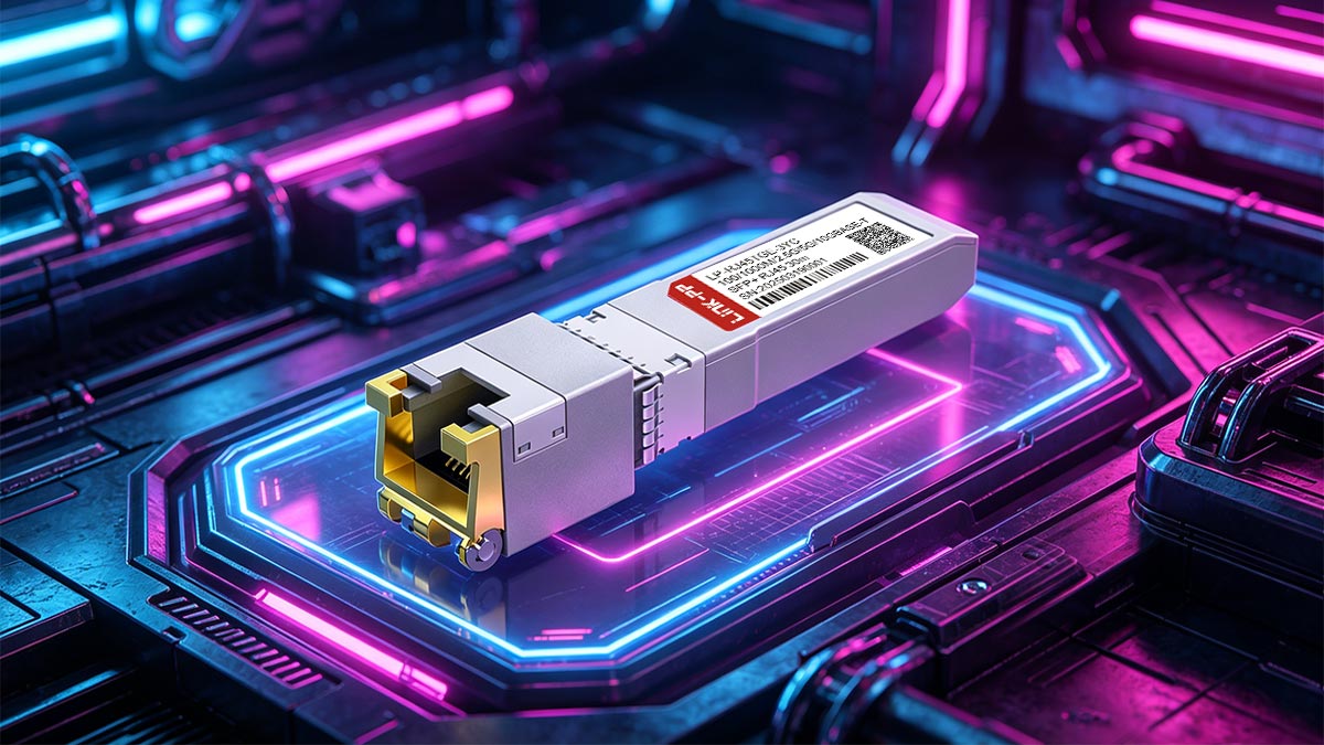
What is 10GbE RJ45 SFP
A 10GbE RJ45 SFP transceiver is a hot-swappable transceiver that allows network devices such as switches and servers to support 10-Gigabit Ethernet over copper cables (typically Cat6a or Cat7). Unlike fiber optic SFP module, it integrates advanced PHY (physical layer) chips to handle complex electrical signaling required for high-speed data transmission over twisted-pair cabling.
These modules are designed for short-distance links, usually up to 30 - 100m depending on cable quality. Their main advantage lies in leveraging existing copper infrastructure, reducing deployment costs while maintaining high bandwidth.
The Evolution of High-speed Ethernet Modules
Ethernet modules have evolved significantly to meet increasing bandwidth demands. Early Gigabit Ethernet relied heavily on copper 1000BASE-T SFP modules, but as speeds increased to 10Gbps, optical transceiver became the dominant solution due to signal limitations in copper.
However, advancements in signal processing, encoding techniques, and chip design led to the development of 10GBASE-T, which made 10GbE RJ45 SFP modules possible. These innovations include sophisticated echo cancellation, forward error correction (FEC), and digital signal processing (DSP), allowing reliable high-speed transmission over copper.
Today, 10GbE RJ45 SFP modules represent a balance between performance and cost, offering an alternative to optical modules in scenarios where ultra-low latency is not the primary requirement.
10GbE RJ45 Copper SFP vs Fiber SFP Module
When comparing 10GbE RJ45 SFP and fiber optic SFP modules, the key differences lie in transmission medium, performance characteristics, and deployment scenarios. 10GbE RJ45 SFP modules use copper cabling and are well-suited for environments with existing Ethernet infrastructure, while fiber optic 10G SFP+ modules rely on optical transmission for higher efficiency and longer reach.
In practical deployments, the choice between these two types often depends on factors such as distance requirements, latency sensitivity, and power constraints. RJ45 copper transceivers offer convenience and cost savings, whereas fiber optic SFP modules excel in high-performance and long-distance applications.
To clearly highlight these differences, the following table provides a side-by-side comparison of 10GbE RJ45 copper SFP and fiber SFP modules:
| Feature | 10GbE RJ45 SFP Module | 10GbE Fiber SFP Module |
| Transmission Medium | Twisted-pair copper cable (Cat6a/7) | Optical fiber cable (MMF/SMF) |
| Standard | 10GBASE-T | 10GBASE-R (SR / LR / ER) |
| Transmission Distance | Up to 30 - 100m | 300m (MMF) to 10km+ (SMF) |
| Latency | Higher (due to DSP processing) | Lower |
| Power Consumption | Higher (typically 2–3W) | Lower (typically <1.5W) |
| Cost (Cabling & Deployment) | Lower (reuse copper cabling) | Higher (fiber + optics needed) |
| EMI Resistance | More susceptible | Highly resistant |
Why Latency Matters in 10GbE Connections
Latency refers to the time it takes for data to travel from one point to another, and it becomes increasingly important in high-speed networks. Even small delays at the physical layer can accumulate, impacting overall application performance.
In 10GbE RJ45 SFP modules, latency is influenced by factors such as signal encoding, error correction, and digital signal processing. Compared to fiber SFP modules, copper SFP solutions typically introduce additional delay due to the complexity of handling electrical signals over twisted pairs.
For latency-sensitive applications — such as financial trading, real-time analytics, or high-performance computing — understanding and managing these delays is critical. Selecting the appropriate module type and optimizing the network design can significantly improve performance outcomes.
🔵 10GbE RJ45 SFP Signal Transmission Principles
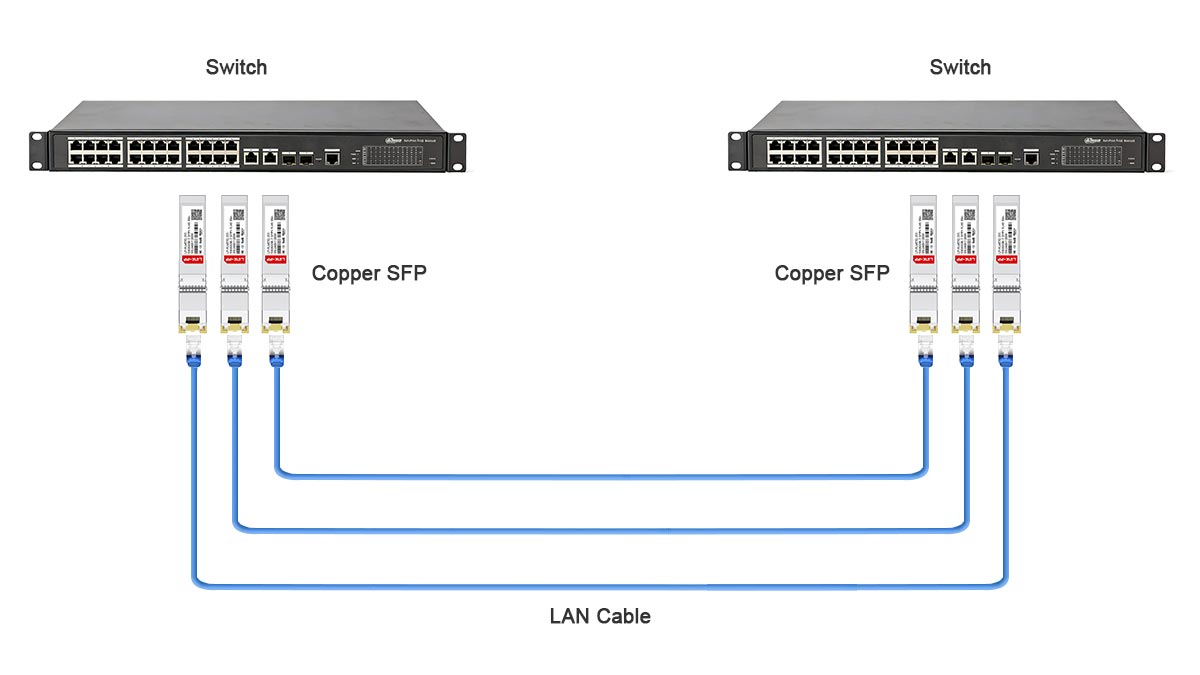
Signal transmission within 10GbE RJ45 SFP modules is governed by high-speed electrical design principles that ensure reliable data transfer at 10 Gbps over copper cabling. The process involves precisely managed encoding, advanced signal conditioning, and robust mitigation against interference and attenuation. Understanding these principles is essential for achieving stable performance and maintaining low bit-error rates in real-world network environments.
Basic Electrical Signaling and Encoding Mechanisms
10GbE RJ45 SFP modules use the 10GBASE-T standard, which relies on complex modulation techniques to optimize data throughput over twisted-pair cables. The system transmits data across all four pairs of copper wires simultaneously, employing Pulse Amplitude Modulation with 16 discrete levels (PAM-16). This encoding enables a 10 Gbps data rate within the electrical limitations of copper while maintaining backward compatibility with lower-speed Ethernet technologies.
To handle such high frequencies, transceivers incorporate advanced digital signal processing (DSP) that compensates for channel imperfections in real time. Forward Error Correction (FEC) and scrambling algorithms further enhance reliability by reducing error probability and electromagnetic interference. The result is a balanced trade-off between speed, signal complexity, and practical copper cable deployment distances.
Data Integrity and Interference Management
Preserving data integrity at 10Gbps requires precise control over electromagnetic coupling and crosstalk between cable pairs. 10GbE RJ45 SFP modules apply adaptive equalization and echo cancellation techniques within the PHY layer to mitigate these distortions. These circuits dynamically adjust transmission characteristics based on signal feedback, ensuring stable performance regardless of cable quality or environment.
Interference management extends beyond the electrical design of the module itself. Proper grounding and shielding of RJ45 connectors, along with the use of high-quality twisted-pair cables (Cat6a or Cat7), are critical. The module’s internal filtering circuits and line drivers also play a key role by suppressing external noise sources, maintaining clean signal edges, and maximizing eye diagram visibility for accurate data recovery.
Cable Length and Signal Degradation Factors
Signal degradation is an inherent challenge when transmitting data over copper cables, and it becomes more pronounced as the cable length increases. For 10GbE RJ45 SFP modules, the maximum cable length typically ranges from 30m to 100m, depending on the quality of the copper cable and the encoding schemes used. As the signal travels through the cable, resistance and capacitance cause the electrical signal to weaken and distort, which can lead to errors in data transmission.
Several factors influence the extent of signal degradation, including cable quality, cable gauge, and the environment in which the cable is installed. For instance, cables with better insulation and lower resistance, such as Cat6a or Cat7 cables, can maintain the signal integrity over longer distances. Additionally, signal repeaters and equalization techniques may be used to compensate for signal loss, though they add complexity and cost to the overall deployment.
Comparison of Copper vs Fiber Signal Performance
Copper and fiber media differ fundamentally in how they manage data transmission, latency, and signal loss. Copper-based 10GbE RJ45 SFP modules convert electrical signals, while fiber SFP modules use light pulses through glass strands. Electrical transmission faces inherent bandwidth limitations due to resistance and electromagnetic interference, but it remains far more cost-effective for short links.
In contrast, fiber SFP modules deliver virtually zero attenuation over moderate distances and exhibit extremely low latency. However, deploying fiber involves specialized infrastructure and delicate maintenance requirements. As a result, copper RJ45 SFP modules are favored for short-link runs in server rooms and top-of-rack connections, while fiber SFP still dominates backbone deployments where distance and performance consistency are paramount.
🔵 Components Inside a 10GbE RJ45 SFP Module
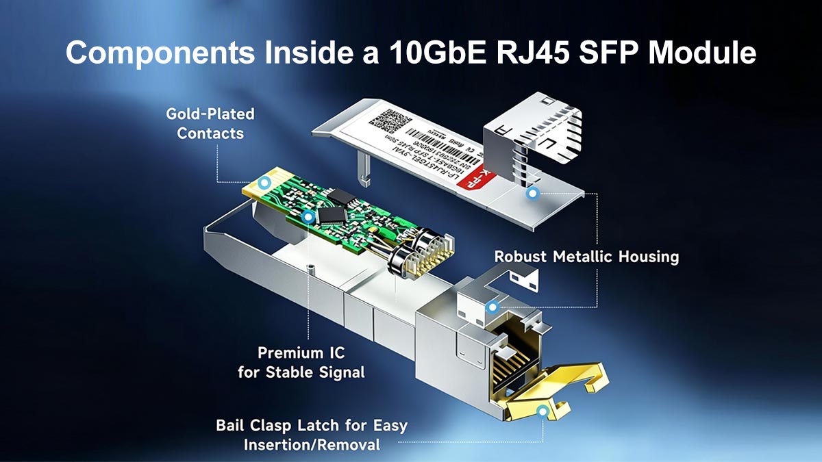
A 10GbE RJ45 SFP module integrates several precision-engineered components that work together to achieve stable 10Gbps communication over copper cabling. These components manage high-frequency signal conversion, conditioning, and thermal regulation within a compact housing. Understanding their functions helps engineers evaluate module quality, optimize performance, and ensure long-term reliability in demanding network environments.
Transceiver IC Architecture Overview
At the core of the 10GbE RJ45 SFP module lies the transceiver integrated circuit (IC), which performs essential physical-layer functions such as analog-to-digital conversion, line coding, and adaptive signal equalization. It bridges the electrical Ethernet MAC interface with the RJ45 connector interface while executing PAM-16 modulation and DSP-based compensation. Advanced transceiver ICs incorporate FEC (Forward Error Correction) engines and EEE (Energy-Efficient Ethernet) functionality, reducing both bit-error rates and unnecessary power draw during idle periods.
Signal Conditioning and Pre-emphasis Circuits
Because high-speed copper links suffer from attenuation and phase distortion, 10GbE RJ45 SFP modules employ signal conditioning circuits to maintain waveform integrity. Pre-emphasis amplifies high-frequency components before transmission, offsetting expected cable losses. On the receive side, equalization and echo-cancellation circuits restore degraded signals by filtering reflections and improving eye diagram characteristics. Together, these circuits ensure data can travel through copper links with minimal jitter and timing skew.
Thermal Design and Power Consumption Control
Operating at multi-gigabit frequencies generates considerable heat within a confined SFP housing. To manage this, RJ45 SFP modules use efficient heat-spreading materials, miniature heat sinks, and thermally optimized metal enclosures. The transceiver IC dynamically adjusts voltage and operating modes depending on traffic load, balancing thermal output and power efficiency. Maintaining junction temperatures below critical thresholds not only safeguards performance stability but also prolongs component lifespan.
PCB Layout Considerations for Signal Quality
The internal printed circuit board (PCB) layout plays a decisive role in preserving signal integrity and electromagnetic compatibility. Differential pair routing must maintain controlled impedance, matched trace lengths, and minimal crosstalk. Careful placement of ground planes and power decoupling capacitors reduces noise coupling between digital and analog sections. These layout optimizations, when executed precisely, allow the 10GbE RJ45 SFP module to achieve full 10G performance without excessive signal degradation or EMI emissions.
🔵 10GbE RJ45 SFP Latency Analysis
Latency is a defining factor in overall network responsiveness, reflecting the time taken for data signals to travel through physical media and processing layers. In 10GbE RJ45 SFP modules, latency arises from a combination of electrical transmission delays, encoding complexity, and digital signal processing overhead. A clear understanding of these sources allows network designers to optimize performance and maintain sub-microsecond transmission efficiency.
Measuring Physical Layer Latency
The physical layer latency within a 10GbE RJ45 SFP can be understood as the time required for a single bit to propagate through the module and cable. Measurement typically involves bit-level timing analysis using test instruments such as oscilloscopes and BERT (Bit Error Rate Testers).
Key measurement considerations include:
- Propagation delay, determined by cable length and medium type.
- Serialization/deserialization delay (SerDes), caused by encoding and bit processing within the transceiver IC.
- DSP and FEC processing time, added by error correction and signal reconstruction algorithms.
By combining these figures, engineers can estimate total one-way latency — usually ranging between 2 and 3 microseconds for copper-based 10GBASE-T links over short runs.
Factors Influencing Signal Delay in Copper-based Links
Several interrelated factors contribute to additional latency in copper-based 10GbE connections:
- Signal Encoding Complexity: PAM-16 modulation and echo cancellation introduce processing overhead not present in fiber-based links.
- Cable Impedance and Length: The longer the cable, the higher the propagation delay; impedance mismatches can further distort signal timing.
- Temperature and Electrical Noise: Variations affect signal propagation speed and recovery accuracy.
- PHY Layer Architecture: The sophistication of DSP design and quality of line drivers directly influences real-time latency handling.
While copper introduces slightly higher latency than optical links, its delay remains predictable and manageable through proper hardware design and installation practices.
Strategies for Latency Optimization
Minimizing latency in 10GbE RJ45 SFP deployments can be achieved through a combination of hardware and configuration strategies:
- Use High-quality Cabling: Cat6a or Cat7 cables reduce signal loss and crosstalk, lowering propagation delay.
- Optimize Transceiver Placement: Minimizing the number of intermediary devices and keeping copper runs short reduces delay.
- Select Low-latency Modules: Some SFP modules are specifically designed with faster DSP and streamlined encoding to reduce physical layer latency.
- Proper Thermal Management: Keeping modules within optimal operating temperatures prevents additional delay caused by thermal throttling of transceiver circuits.
By addressing these areas, network engineers can significantly reduce latency, improving the responsiveness and performance of high-speed copper-based Ethernet networks.
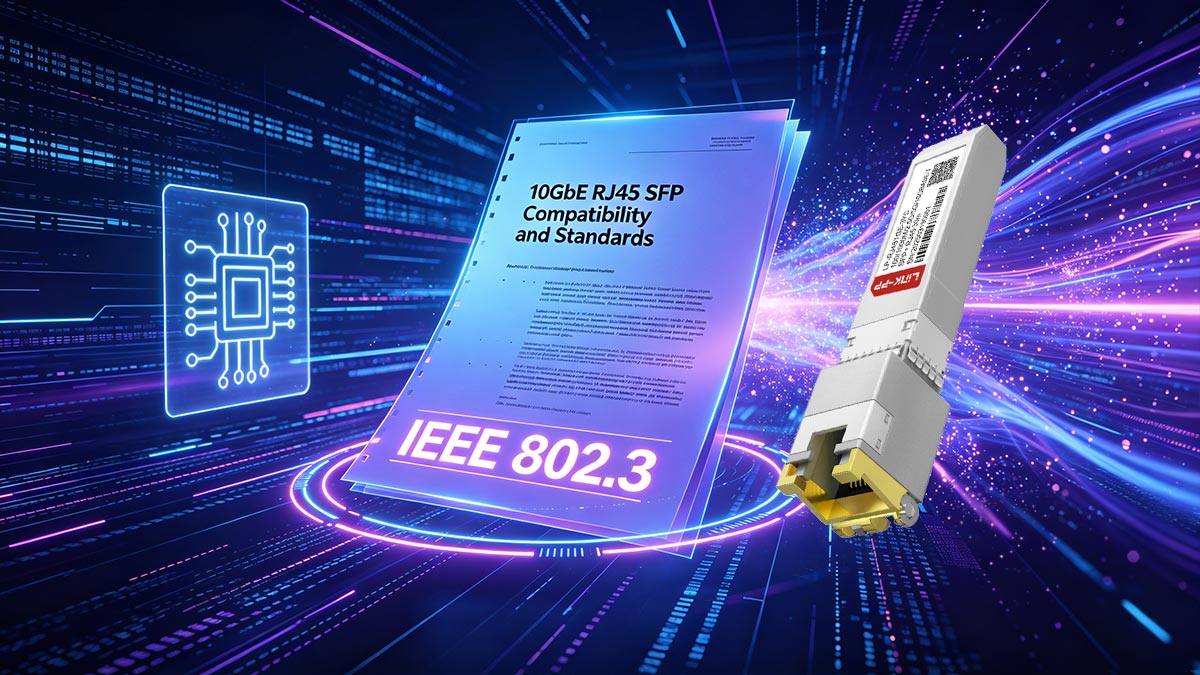
🔵 10GbE RJ45 SFP Compatibility and Standards
Ensuring compatibility and adherence to standards is essential for the reliable operation of 10GbE RJ45 SFP modules across different network devices and environments. These standards define electrical, mechanical, and signaling requirements, while compatibility considerations ensure that modules from different vendors can interoperate without issues.
IEEE 802.3an and Related Standards Overview
The IEEE 802.3an standard, also known as 10GBASE-T, defines the specifications for 10‑Gigabit Ethernet over twisted‑pair copper cabling. It covers electrical signaling, encoding methods, link distance limits, and maximum allowable crosstalk and noise levels. Compliance with IEEE 802.3an ensures that 10GbE RJ45 SFP modules can reliably interconnect with other certified devices and maintain consistent performance across networks.
In addition to 802.3an, several related standards influence module design, for example:
- IEEE 802.3az (Energy‑Efficient Ethernet): reduces power consumption during low‑traffic periods using low‑power idle modes.
- SFP+ MSA and SFF‑8431: the SFP+ MSA defines the multi‑source agreement for the physical form factor and electrical interface of SFP+ modules, while SFF‑8431 specifies their mechanical and electrical requirements in detail.
- Cabling standards: such as TIA/EIA‑568‑C.2 (for Cat6a cabling) and ISO/IEC 11801 Class F (for Cat7 cabling).
Together, these standards provide a framework that guides manufacturers in producing modules that meet both the electrical and physical requirements for high‑speed Ethernet.
Interoperability between Different Vendor Modules
Interoperability is a crucial consideration for network deployments that use 10GbE RJ45 SFP modules from multiple vendors. Modules may differ in their firmware, PHY chipsets, or electrical characteristics, which can sometimes lead to compatibility issues. Key aspects include:
- Ensuring the module conforms to IEEE 802.3an specifications.
- Verifying that vendor-specific modules support standard hot-swapping and auto-negotiation features.
- Testing connectivity in the actual network environment to confirm proper operation.
By addressing these points, network engineers can reduce the risk of module incompatibility and maintain a stable, high-performance network.
Firmware and PHY Layer Compatibility Challenges
Firmware and PHY (physical layer) differences between modules can affect performance and compatibility. Variations in error handling, DSP algorithms, or timing may lead to reduced throughput, increased latency, or intermittent connectivity issues. Careful attention to firmware versions, PHY revisions, and manufacturer interoperability lists is necessary to ensure modules function correctly across devices. Updating firmware and adhering to vendor-recommended configurations can often resolve these challenges.
Certification and Testing Requirements
Certification and testing are essential to validate that 10GbE RJ45 SFP modules meet industry standards and perform reliably in real-world conditions. Common testing procedures include:
- Electrical testing to verify signal integrity, eye patterns, and crosstalk levels.
- Interoperability testing with switches, routers, and servers from different vendors.
- Environmental testing to ensure module stability under varying temperatures, humidity, and EMI conditions.
Certification from recognized bodies or independent labs provides assurance that the module complies with standards and will operate consistently in professional networks.
🔵 10GbE RJ45 SFP Performance Testing and Benchmarking
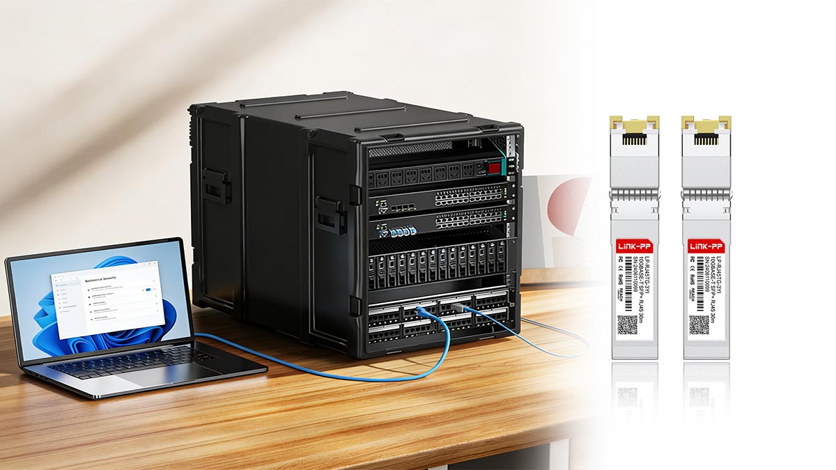
Performance testing and benchmarking are essential for validating the reliability, signal integrity, and latency characteristics of 10GbE RJ45 SFP modules. Proper evaluation ensures that these modules meet network requirements and can operate consistently under various conditions.
Common Tools for Signal and Latency Measurement
Engineers rely on specialized test equipment to quantify 10GbE RJ45 SFP performance, including high-bandwidth oscilloscopes for eye diagram analysis, Bit Error Rate Testers (BERTs) for BER validation, and network impairment simulators for latency profiling. Protocol analyzers like Wireshark or specialized Ethernet testers (e.g., EXFO or Viavi solutions) capture packet-level timing and jitter, while vector network analyzers measure cable return loss and crosstalk. These tools collectively provide quantitative metrics for signal quality, link stability, and end-to-end performance.
Environmental Impacts on Test Accuracy
Temperature, humidity, and EMI significantly influence test results for 10GbE RJ45 SFP modules, as copper links are particularly sensitive to thermal expansion and electrical noise. Elevated temperatures increase cable attenuation and PHY processing delays, while high humidity can degrade connector performance through oxidation. Accurate benchmarking requires environmental chambers to simulate data center conditions (0 - 70°C), ensuring measurements reflect operational reality rather than idealized lab settings.
Test Setup and Configuration Guidelines
A proper test setup for 10GbE RJ45 SFP benchmarking includes matched Cat6a/Cat7 cables of varying lengths, reference-grade switches with known-good SFP+ ports, and calibrated test equipment connected via loopback or back-to-back configurations. Auto-negotiation must be enabled to verify multi-rate compatibility (100M SFP/1G SFP/10G SFP+), with traffic generators stressing full-duplex 10Gbps loads. Document baseline performance across multiple module samples, recording BER (<10⁻¹²), latency (<5μs round-trip), and power draw to establish quality benchmarks and detect manufacturing variances.
🔵 10GbE RJ45 SFP Design Considerations for System Integrators
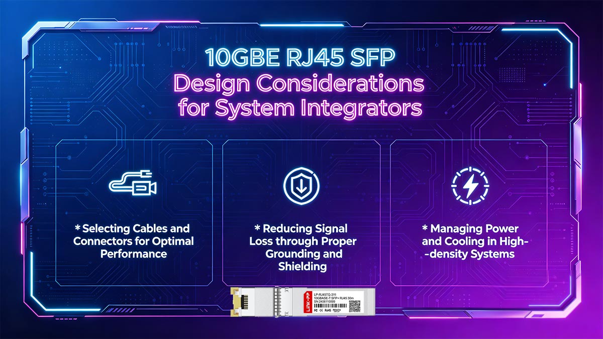
Integrating 10GbE RJ45 SFP modules into high-performance networks requires more than just plugging in transceivers; careful attention to cabling, signal integrity, and system environment is essential. System integrators must optimize every aspect — from physical connectivity to power and thermal management — to ensure reliable 10Gbps operation while minimizing latency and interference.
Selecting Cables and Connectors for Optimal Performance
For optimal performance, system integrators should use certified Cat6a or Cat7 cables that support 10Gbps transmission with minimal crosstalk and attenuation. The quality of connectors is equally important; poor connectors can introduce reflections and impedance mismatches, reducing signal integrity. Cable routing should avoid sharp bends, excessive twists, or proximity to high-voltage lines, and patch panels should be chosen for low insertion loss to maintain consistent signal quality across all links.
Reducing Signal Loss through Proper Grounding and Shielding
Signal loss and electromagnetic interference (EMI) can significantly degrade 10GbE RJ45 SFP performance, especially in dense installations. Proper grounding of modules, switches, and patch panels ensures a stable reference potential, preventing unwanted currents that could introduce noise. Shielded twisted-pair (STP) cables and shielded racks help isolate the network from external EMI sources, and careful attention to grounding continuity reduces crosstalk between adjacent copper pairs, preserving high-speed signal fidelity.
Managing Power and Cooling in High-density Systems
High-density deployments of 10GbE RJ45 SFP modules can generate significant heat, which impacts both latency and module lifespan. Integrators should ensure adequate airflow around modules and switches, possibly using directed cooling or rack-mounted fans. Selecting modules with low power consumption helps reduce thermal load, and monitoring operating temperatures in real-time allows proactive management. Thermal considerations also extend to PCB layout within the module, as hotspots can cause signal degradation and increase bit error rates if not properly managed.
🔵 Conclusion: Optimizing Signal Integrity and Latency in 10GbE RJ45 SFP Networks
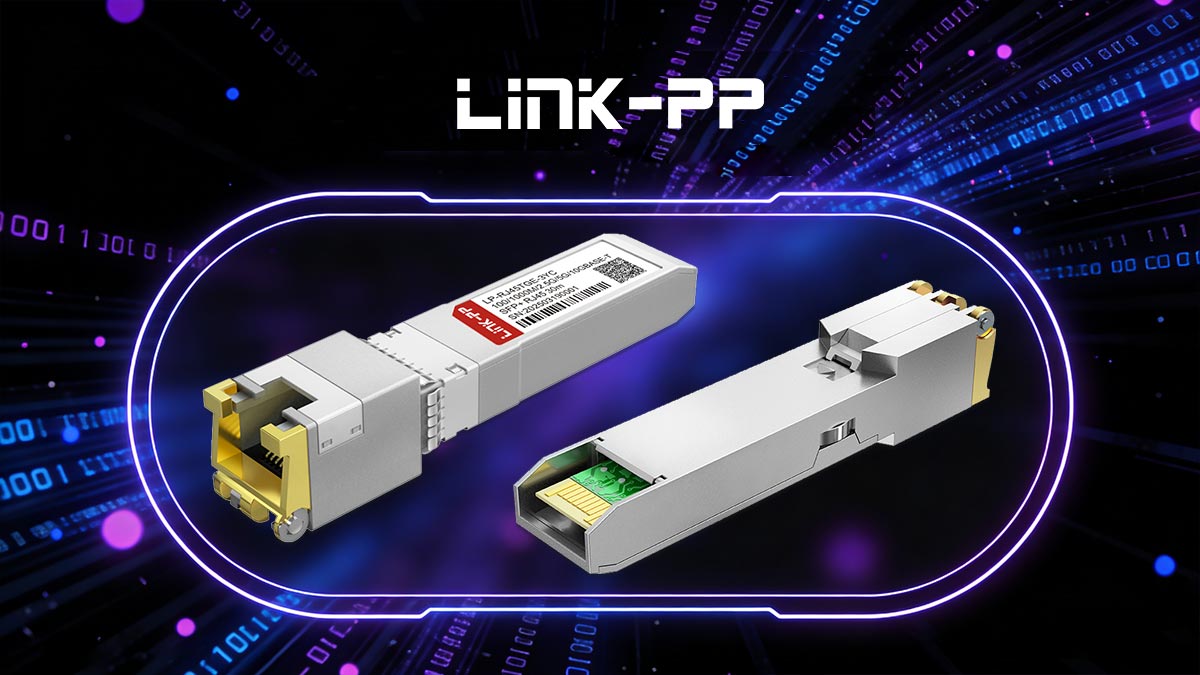
Ensuring optimal performance in 10GbE RJ45 SFP networks requires attention to signal integrity, latency, and compatibility. By carefully selecting high-quality modules, using proper cabling and shielding, and managing power and thermal conditions, network designers can achieve reliable 10 Gbps connectivity with minimal errors and delays.
For those seeking dependable 10GbE RJ45 SFP modules, the LINK-PP Official Store offers a wide range of certified modules designed for high-speed, low-latency networks, providing a trusted solution for upgrading or expanding your network infrastructure.







