



































In industrial Ethernet networks, Hirschmann M-SFP-SX-LC modules are widely recognized for their reliability and compatibility with industrial switches. However, network engineers often need alternative transceiver modules due to supply limitations, cost considerations, or deployment flexibility. Evaluating these replacement modules requires not only confirming functional compatibility but also assessing their thermal performance.
Heat dissipation is a critical factor in industrial environments, where transceivers may operate under elevated temperatures or limited airflow. Excessive heat can reduce signal integrity, shorten module lifespan, and even trigger link instability. Therefore, understanding how third-party replacements manage heat is essential for maintaining a stable and long-lasting network.
This article focuses on heat dissipation testing of replacement modules for Hirschmann M-SFP-SX-LC 1G SFP module. It provides an overview of test methodology, analyzes thermal performance under real-world conditions, and offers practical guidance for deploying these replacements in industrial settings. By the end, you will gain a clear understanding of how to select and implement modules that maintain both performance and reliability.
? Overview of Hirschmann M-SFP-SX-LC and Replacement Modules
Understanding the baseline specifications of the original optical transceiver and the expectations placed on replacement options is essential for evaluating thermal performance. In short, reliable replacement modules must match the electrical, optical, and environmental characteristics of Hirschmann M-SFP-SX-LC while maintaining stable operation under industrial temperature conditions.

Key Specifications of Hirschmann M-SFP-SX-LC
Hirschmann M-SFP-SX-LC is designed for industrial-grade Gigabit Ethernet connectivity over multimode fiber. Its specifications define the performance and thermal baseline that any replacement module must meet or exceed.
The following table summarizes the core technical parameters:
| Parameter | Specification | Notes |
|---|---|---|
| Data Rate | 1Gbps | 1000BASE-SX standard |
| Wavelength | 850nm | Optimized for MMF |
| Fiber Type | Multimode (OM2/OM3) | Up to 550m reach |
| Interface | LC Duplex | Standard SFP form factor |
| Operating Temp | -40°C to 85°C | Industrial-grade range |
These specifications highlight two critical aspects. First, the module operates within a wide temperature range, making thermal stability a core requirement rather than an optional feature. Second, its relatively low power consumption compared to other high-speed transceivers and Fibre Channel modules does not eliminate heat concerns, especially in dense or poorly ventilated deployments.
Typical Replacement Module Requirements
Replacement modules must deliver equivalent functionality while ensuring seamless interoperability with Hirschmann switches. The key conclusion is that compatibility alone is insufficient; thermal behavior must also align with industrial expectations.
To achieve this, replacement modules are generally expected to meet the following requirements:
- Electrical and protocol compatibility
- Support for 1000BASE-SX operation
- Stable link establishment without negotiation issues
- Vendor recognition and integration
- Proper EEPROM coding for Hirschmann devices
- No port shutdown or warning triggers
- Diagnostic capability
- Mechanical and thermal alignment
- Standard SFP form factor with proper cage contact
- Efficient heat transfer to the host device
These requirements ensure that replacement modules behave identically to the original in real deployments. Even when optical performance is equivalent, differences in internal design or materials can lead to variations in heat accumulation and dissipation, which directly affect long-term reliability.
Importance of Thermal Performance in Replacements
Thermal performance is one of the most critical factors distinguishing high-quality replacements from lower-grade alternatives. In practical terms, modules that cannot dissipate heat effectively are more likely to experience instability under continuous operation.
The impact of thermal performance can be understood across several key dimensions:
- Environmental stress conditions
- Industrial cabinets often lack active cooling
- Ambient temperatures may exceed standard commercial limits
- Operational continuity
- 24/7 uptime requirements increase thermal load
- Heat buildup over time can degrade internal components
- Network reliability risks
- Elevated temperatures increase bit error rates
- Thermal stress may cause intermittent link failures
To better illustrate the difference between original and replacement modules in thermal context, the table below compares typical characteristics:
| Aspect | Original Module | Replacement Module (Varies) |
|---|---|---|
| Thermal Design | Optimized for industrial | Depends on vendor design |
| Material Quality | High-grade metal casing | May vary |
| Heat Dissipation Path | Efficient | Potentially less consistent |
| Long-Term Stability | Proven | Requires validation |
This comparison shows that while replacement modules can match functional specifications, their thermal performance is not always guaranteed. As a result, heat dissipation testing becomes a necessary step to verify whether a replacement module can sustain stable operation in demanding industrial environments.
? Fundamentals of Heat Dissipation in SFP Modules
Heat dissipation in SFP modules is governed by how efficiently internally generated heat is transferred to the external environment. In practical terms, stable operation depends on balancing power consumption, thermal design, and environmental conditions. Understanding these fundamentals helps explain why some replacement modules perform reliably while others fail under identical deployment scenarios.
Sources of Heat Generation
The primary conclusion is that heat in fiber SFP modules originates from electrical-to-optical conversion and internal signal processing, even at relatively low data rates like 1Gbps.
Heat generation inside a typical fiber optic SFP module can be attributed to several core components:
- Optical transmission elements
- Laser diode (VCSEL for 850nm) generates heat during light emission
- Driver circuitry amplifies signals, contributing to power loss
- Receiver-side components
- Photodiode converts optical signals back to electrical signals
- Transimpedance amplifier (TIA) processes weak signals, generating heat
- Digital and control circuits
- EEPROM and monitoring ICs (for DOM/DDM)
- Clock and data recovery (CDR) or equivalent logic
To better understand how these sources contribute to overall thermal output, the following table summarizes typical contributors:
| Component | Function | Heat Contribution Level |
|---|---|---|
| Laser Diode (VCSEL) | Optical signal generation | Medium |
| Driver IC | Signal amplification | Medium to High |
| Receiver (TIA + PD) | Signal detection | Medium |
| Control ICs | Monitoring and communication | Low |
Although each component generates a moderate amount of heat individually, their combined effect leads to measurable temperature rise within the compact SFP enclosure. This cumulative heat must be effectively dissipated to avoid thermal buildup.
Thermal Design Mechanisms
Efficient heat dissipation depends on how well the module is designed to transfer internal heat outward. The key point is that SFP modules rely primarily on passive cooling, making physical design and material selection critical.
Several design mechanisms contribute to thermal performance:
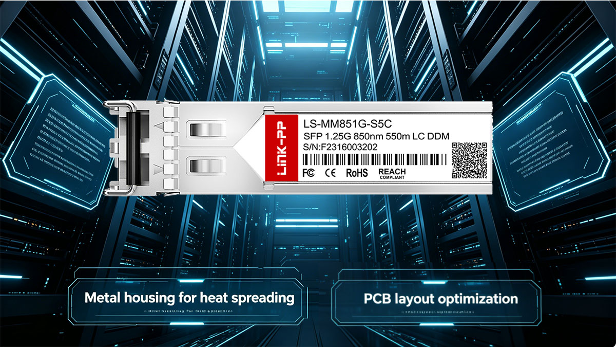
- Metal enclosure as a heat spreader
- Conducts heat away from internal components
- Distributes heat evenly across the module surface
- Internal PCB layout optimization
- Strategic placement of heat-generating components
- Use of thermal vias to transfer heat between layers
- Contact with the SFP cage
- Direct metal-to-metal contact enables heat transfer to the host device
- The switch chassis acts as an extended heat sink
- Airflow interaction
- Even minimal airflow improves convective cooling
- Lack of airflow leads to heat accumulation
These mechanisms work together as a passive thermal system. Unlike active cooling systems, SFP modules depend entirely on conduction and convection, which makes their performance highly sensitive to both design quality and deployment conditions.
Key Thermal Metrics to Evaluate
Thermal performance is quantified using several measurable parameters. The core conclusion is that evaluating these metrics provides a reliable way to compare original and replacement modules under real operating conditions.
The most relevant thermal metrics are summarized below:
| Metric | Definition | Practical Significance |
|---|---|---|
| Case Temperature (Tc) | Temperature at module surface | Indicates external heat level |
| Junction Temp (Tj) | Internal semiconductor temperature | Critical for component health |
| Power Dissipation | Total energy converted to heat (W) | Directly affects heat output |
| Thermal Resistance | Heat transfer efficiency (°C/W) | Lower values indicate better cooling |
These metrics are closely interrelated. For example, higher power dissipation typically leads to increased junction temperature, unless offset by efficient thermal design. Similarly, a module with lower thermal resistance can maintain a lower case temperature under the same workload.
In practical testing, case temperature is the most accessible metric, while junction temperature is often inferred. Together, they provide a comprehensive view of how effectively a module manages heat, especially when operating in industrial environments with elevated ambient temperatures.
? Heat Dissipation Test Methodology for Replacement Modules
A reliable heat dissipation evaluation requires a controlled, repeatable methodology that simulates real deployment conditions. The key takeaway is that accurate thermal assessment depends on combining environmental control, precise measurement tools, and realistic workload scenarios. Without these elements, test results may not reflect actual field performance.
Test Environment Setup
A well-defined test environment ensures that thermal results are consistent and comparable across different modules. The main conclusion is that both ambient temperature and airflow conditions must be carefully controlled, as they directly influence heat accumulation.
A typical test environment includes the following conditions:
- Controlled ambient temperature
- Standard baseline (e.g., 25°C) for reference comparison
- Elevated conditions (e.g., 55°C–70°C) to simulate industrial environments
- Airflow scenarios
- No-airflow (passive cooling) to replicate sealed enclosures
- Forced airflow to simulate ventilated switch systems
- Physical installation consistency
- Modules inserted into the same switch model
- Identical port positioning to avoid airflow bias
To standardize these conditions, the following setup parameters are commonly used:
| Test Factor | Configuration Example | Purpose |
|---|---|---|
| Ambient Temp | 25°C / 55°C / 70°C | Simulate real environments |
| Airflow | 0 LFM / controlled airflow | Compare passive vs active cooling |
| Mounting Position | Fixed port location | Ensure consistency |
| Test Duration | 24–72 hours | Capture thermal stability |
By maintaining strict control over these variables, engineers can isolate the thermal behavior of the replacement module itself, rather than external influences.
Testing Equipment and Tools
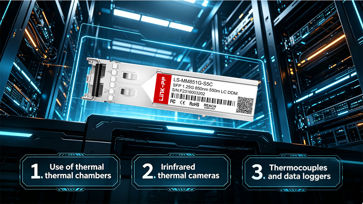
Accurate thermal measurement requires specialized tools capable of capturing both surface and internal temperature variations. The key point is that combining multiple measurement methods provides a more complete thermal profile.
Commonly used testing tools include:
- Infrared thermal cameras
- Capture real-time surface temperature distribution
- Identify hotspots across the module housing
- Thermocouples and sensors
- Provide precise point-based temperature readings
- Typically attached to the module case (Tc measurement)
- Data loggers
- Record temperature changes over time
- Enable long-duration trend analysis
- Network traffic generators
- Simulate real data load conditions
- Ensure consistent utilization during testing
These tools complement each other. For example, thermal cameras reveal spatial heat patterns, while thermocouples provide accurate numerical data. When used together, they allow both qualitative and quantitative analysis of heat dissipation.
Test Scenarios and Parameters
Thermal performance must be evaluated under different operating conditions to reflect real-world usage. The main conclusion is that both workload intensity and duration significantly impact heat buildup and stability.
Typical test scenarios include:
- Idle condition testing
- Minimal traffic load
- Establishes baseline temperature behavior
- Full-load operation
- Continuous 1Gbps traffic transmission
- Represents worst-case thermal conditions
- Long-duration stability testing
- Continuous operation over 24–72 hours
- Identifies gradual heat accumulation and drift
- High-temperature stress testing
- Elevated ambient temperature (e.g., 70°C)
- Simulates harsh industrial environments
The following table summarizes how these scenarios are structured:
| Scenario | Load Condition | Duration | Objective |
|---|---|---|---|
| Idle Test | Low/No traffic | Short-term | Baseline temperature |
| Full Load Test | 100% utilization | Medium-term | Peak thermal behavior |
| Burn-in Test | Continuous load | 24–72 hours | Long-term stability |
| High Temp Stress | Full load | Variable | Performance under extreme heat |
These scenarios are designed to progressively stress the module. While idle tests confirm basic thermal behavior, full-load and high-temperature tests reveal whether a replacement module can maintain stable operation under demanding conditions.
By combining controlled environments, precise instrumentation, and realistic test scenarios, this methodology provides a comprehensive framework for evaluating the heat dissipation performance of replacement modules for Hirschmann M-SFP-SX-LC.
? Test Results and Thermal Performance Analysis
Thermal testing reveals how replacement modules behave under real operating stress and whether they can match the stability of the original Hirschmann M-SFP-SX-LC. The main conclusion is that while many replacement modules meet basic functional requirements, their thermal performance can vary significantly depending on design quality, materials, and environmental conditions.

Temperature Distribution Observations
Thermal imaging and sensor data show that heat is not evenly distributed across the module. The key finding is that specific internal components consistently create localized hotspots, which can become critical under high ambient temperatures.
Typical temperature distribution characteristics include:
- Hotspot concentration areas
- Near the laser driver IC and optical transmitter section
- Around power regulation components
- Surface vs internal temperature differences
- External case temperature (Tc) is usually lower than internal junction temperature
- Differences can range from 5°C to 15°C depending on design
- Airflow impact on heat dispersion
- Passive environments show heat accumulation at the top surface
- Even low airflow significantly reduces hotspot intensity
The following table summarizes observed thermal patterns:
| Observation Area | Temperature Behavior | Impact on Performance |
|---|---|---|
| Transmitter Section | Highest hotspot | Affects signal stability |
| Module Surface | Moderate heat spread | Indicates dissipation ability |
| Connector End | Lower temperature | Minimal thermal stress |
| With Airflow | Reduced peak temperature | Improved overall stability |
These observations indicate that effective heat spreading and external dissipation are critical. Modules with poor internal layout tend to show sharper temperature gradients, increasing the risk of localized overheating.
Performance Under Continuous Load
Sustained operation testing highlights how temperature evolves over time. The key conclusion is that stable modules reach a thermal equilibrium, while lower-quality replacements may exhibit continuous temperature rise or fluctuations.
During 24–72 hour testing periods, the following behaviors are commonly observed:
- Stable thermal equilibrium
- Temperature rises initially, then plateaus
- Indicates balanced heat generation and dissipation
- Gradual thermal drift
- Slow temperature increase over time
- Suggests insufficient heat dissipation efficiency
- Thermal instability symptoms
- Fluctuating temperatures under constant load
- Often linked to inconsistent internal design
These behaviors directly affect network performance:
| Condition | Thermal Behavior | Network Impact |
|---|---|---|
| Stable Operation | Temperature plateau | Reliable link performance |
| Thermal Drift | Continuous increase | Increased error rates |
| Thermal Fluctuation | Temperature variation | Intermittent link instability |
| Overheating Threshold | Excessive temperature | Possible module shutdown |
In practice, modules that fail to stabilize thermally are more likely to experience long-term reliability issues. Continuous load testing is therefore essential to validate replacement modules before deployment in critical environments.
Comparison with Original Hirschmann Modules
Comparative analysis provides a clear benchmark for evaluating replacement modules. The main conclusion is that high-quality replacements can approach the thermal performance of the original module, but inconsistencies are common across different vendors.
Key comparison points include:
- Thermal efficiency
- Original modules typically show more uniform heat distribution
- High-quality replacements can achieve similar results with optimized design
- Power consumption
- Slight variations in power draw can lead to noticeable thermal differences
- Less efficient designs generate more heat under identical loads
- Reliability under stress
- Original modules demonstrate consistent performance across temperature ranges
- Replacement modules may vary in long-term stability
The table below illustrates typical comparative outcomes:
| Metric | Original Module | Replacement Module (Typical) |
|---|---|---|
| Peak Case Temp (Tc) | Lower and stable | Slightly higher or variable |
| Heat Distribution | Uniform | May show localized hotspots |
| Power Efficiency | Optimized | Varies by design |
| Long-Term Stability | Proven | Requires validation |
This comparison highlights that thermal performance is not guaranteed even when specifications appear identical. As a result, heat dissipation testing is a critical validation step when selecting replacement modules for Hirschmann M-SFP-SX-LC, especially in industrial environments where temperature margins are limited.
? Factors Affecting Heat Dissipation Efficiency
Heat dissipation efficiency is not determined by a single factor but by the interaction between module design, deployment environment, and operating conditions. In practice, even modules with identical specifications can show very different thermal behavior depending on how these factors combine.
Module Design and Materials
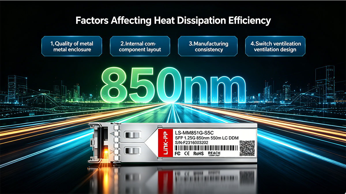
The most decisive factor in heat dissipation is the internal design of the module itself. A well-engineered SFP transceiver can efficiently transfer heat from internal components to the outer casing, while a poorly designed one tends to trap heat internally.
At the core of this difference is how heat flows through the module. High-quality designs typically use metal enclosures with strong thermal conductivity, allowing heat to spread evenly across the surface. In contrast, lower-grade materials or inconsistent manufacturing can create bottlenecks where heat accumulates.
Component placement also plays an important role. When heat-generating elements such as driver ICs and laser components are positioned too closely without proper thermal paths, localized hotspots can form. Over time, these hotspots increase stress on specific components rather than distributing heat evenly across the module.
In addition, the presence of efficient thermal paths—such as optimized PCB layouts or direct contact between components and the casing—determines how quickly heat can be dissipated. Without these pathways, even moderate power consumption can lead to elevated internal temperatures.
Host Device and Deployment Environment
Even a well-designed module can experience poor thermal performance if the surrounding environment limits heat dissipation. The key point is that SFP modules rely heavily on the host device and ambient conditions to remove heat.
Several external factors can significantly influence thermal behavior:
- Airflow conditions
Limited or no airflow prevents heat from being carried away, causing gradual temperature buildup. Even minimal airflow can significantly improve cooling efficiency. - Ambient temperature
Higher environmental temperatures reduce the temperature gradient between the module and its surroundings, making heat transfer less effective. - Port density
When multiple SFP modules are installed side by side, heat from adjacent modules accumulates, raising the overall thermal load. - Switch design
Some industrial switches are designed with better ventilation or heat dissipation paths, while sealed or compact designs may trap heat.
These factors often interact. For example, a high-density deployment in a high-temperature environment with no airflow represents one of the most challenging thermal scenarios, even for high-quality modules.
Cable Type and Network Load
Operational conditions further influence how much heat is generated during runtime. Unlike design or environment, these factors are dynamic and can change depending on network usage.
The most direct driver is traffic load. When a module operates under continuous full utilization, internal components such as the laser driver and receiver circuits remain active at all times, leading to sustained heat generation. In contrast, intermittent traffic allows brief cooling periods that reduce overall thermal buildup.
Link conditions also matter. When operating near maximum transmission distance or over lower-quality multimode fiber, the module may require higher optical output or increased signal processing effort. This additional workload translates into slightly higher power consumption and, consequently, more heat.
To summarize how operational conditions affect thermal output, the following comparison highlights typical differences:
| Condition Type | Lower Thermal Impact | Higher Thermal Impact |
|---|---|---|
| Traffic Pattern | Intermittent | Continuous full load |
| Link Distance | Short range | Near maximum reach |
| Fiber Quality | High-grade MMF | Older or degraded MMF |
These operational factors show that heat dissipation is not static. A module that performs well under light load may behave very differently under sustained high utilization, which is why realistic workload testing is essential.
? Best Practices to Optimize Thermal Performance
Optimizing thermal performance requires a combination of proper deployment, continuous monitoring, and careful module selection. The key takeaway is that heat-related issues can often be prevented through proactive design and operational practices rather than reactive troubleshooting.

Deployment Guidelines
Proper deployment is the first and most effective step in managing heat dissipation. In most cases, ensuring adequate airflow and avoiding thermal concentration points can significantly reduce the risk of overheating.
In practical environments, the following measures have proven effective:
- Maintain sufficient airflow within switch enclosures
Even low levels of airflow can improve heat exchange. Avoid placing switches in sealed cabinets without ventilation. - Avoid fully populating all ports in high-temperature environments
Leaving spacing between active SFP modules helps reduce heat accumulation and improves overall cooling efficiency. - Position switches in thermally stable locations
Avoid installing equipment near heat sources or in direct sunlight, especially in outdoor or industrial settings. - Use switches designed for industrial environments
Devices with optimized thermal architecture can better dissipate heat from installed modules.
These deployment strategies are particularly important in industrial scenarios where environmental conditions are less controllable. Small improvements in airflow or spacing can result in noticeable reductions in operating temperature.
Monitoring and Maintenance
Thermal performance is not a one-time consideration; it requires ongoing monitoring to ensure stability over time. The main point is that early detection of temperature anomalies can prevent long-term failures.
A structured monitoring approach typically includes the following steps:
- Enable DOM/DDM monitoring
This allows real-time tracking of module temperature, voltage, and optical parameters. - Establish baseline temperature ranges
Record normal operating temperatures under typical load conditions to identify deviations later. - Monitor for gradual temperature increases
A slow rise in temperature over time may indicate airflow degradation or component aging. - Perform periodic inspections
Check for dust accumulation, blocked vents, or changes in environmental conditions.
To support monitoring decisions, the table below outlines typical indicators and their implications:
| Indicator | Observation | Recommended Action |
|---|---|---|
| Stable Temperature | Consistent readings | No action required |
| Gradual Increase | Slow upward trend | Check airflow and environment |
| Sudden Spike | Rapid temperature rise | Inspect module and switch |
| Abnormal Fluctuation | Irregular variation | Verify module stability |
Consistent monitoring helps identify potential issues before they affect network performance, especially in long-term industrial deployments.
Selecting Reliable Replacement Modules
Choosing the right replacement module is critical for ensuring long-term thermal stability. The main conclusion is that not all compatible modules offer the same level of thermal performance, even if they meet basic specifications.
When evaluating replacement modules, consider the following factors:
- Compliance with industrial temperature ranges
Modules should support extended operating temperatures (e.g., -40°C to 85°C) to handle harsh environments. - Verified compatibility with Hirschmann devices
Proper integration ensures stable operation without unexpected behavior that could increase thermal stress. - Proven thermal performance
Preference should be given to modules that have undergone heat dissipation testing or long-term validation. - Build quality and consistency
Reliable manufacturing processes reduce variability in thermal behavior across units.
Unlike basic specification matching, these criteria focus on real-world performance. Modules that meet these requirements are more likely to maintain stable temperatures and avoid issues such as thermal drift or intermittent failures.
? Common Thermal Issues and Troubleshooting
Thermal issues in SFP modules typically manifest as instability rather than immediate failure. The key takeaway is that most heat-related problems can be identified early through observable symptoms and resolved by addressing airflow, environment, or module quality.
Symptoms of Overheating
Overheating rarely appears as a single clear error; instead, it presents through a combination of performance anomalies. Recognizing these signs early helps prevent more serious failures.
Common symptoms include:
- Link instability
Connections may intermittently drop and reconnect, especially under sustained traffic load. - Increased bit error rate (BER)
Elevated temperatures can degrade signal quality, leading to transmission errors. - Unexpected module resets or shutdowns
Some modules include thermal protection mechanisms that trigger when temperature thresholds are exceeded. - Gradual performance degradation
Over time, excessive heat can affect internal components, resulting in reduced reliability.
These symptoms often appear progressively. For example, a module may initially show minor errors under high load, which later develop into frequent link interruptions if the thermal condition is not addressed.
Root Cause Analysis
Identifying the root cause is essential for effective troubleshooting. The main conclusion is that thermal issues are usually not caused by a single factor, but by a combination of environmental and design limitations.
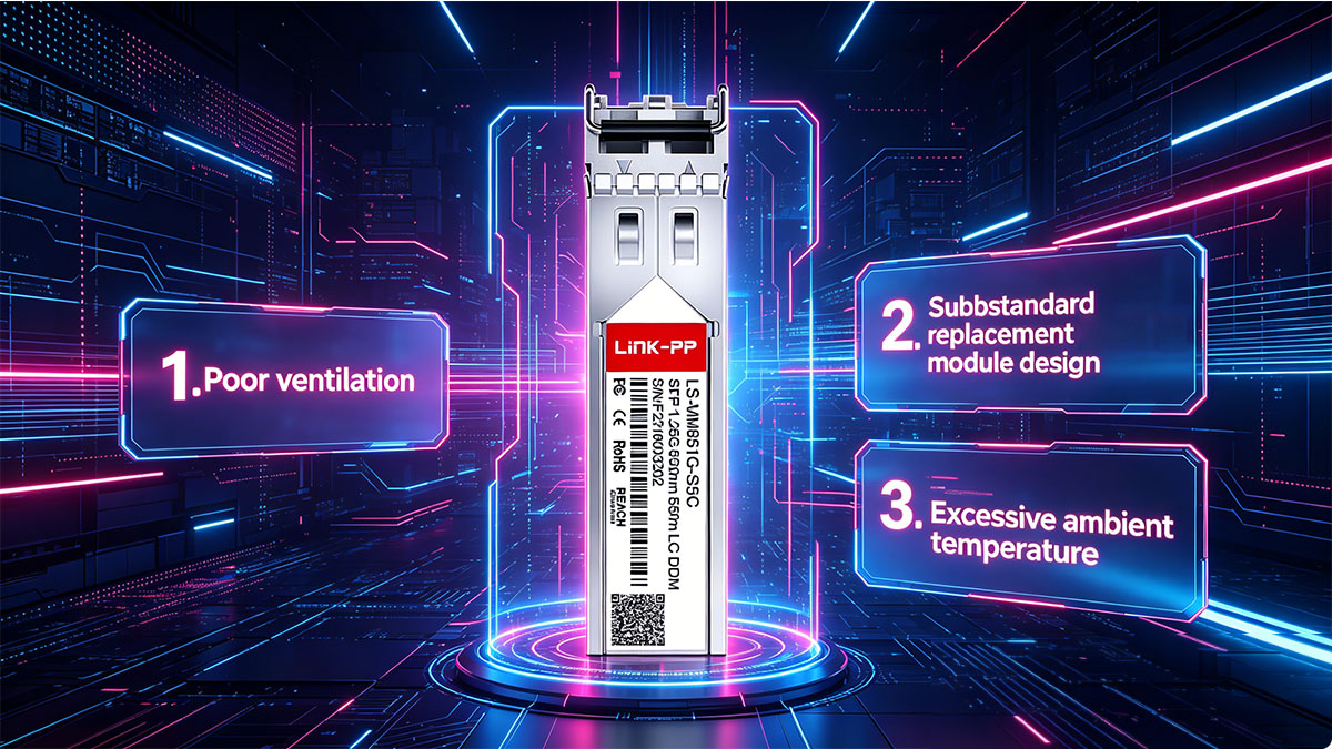
Typical root causes include:
- Insufficient airflow
Lack of ventilation prevents heat from dissipating, causing temperature buildup inside the switch enclosure. - High ambient temperature
Operating in environments close to or beyond the module's rated temperature range reduces cooling efficiency. - High port density
Closely packed modules generate cumulative heat, raising the overall thermal load. - Inconsistent module quality
Replacement modules with suboptimal design or materials may dissipate heat less effectively.
To better connect causes with their effects, the following table provides a simplified mapping:
| Root Cause | Typical Symptom | Impact Level |
|---|---|---|
| Poor Airflow | Gradual temperature rise | Medium to High |
| High Ambient Temp | Persistent overheating | High |
| High Port Density | Localized heat buildup | Medium |
| Low-Quality Module | Instability under load | High |
In many real-world cases, multiple factors occur simultaneously. For instance, a high-density deployment in a warm environment with limited airflow can significantly amplify thermal stress.
Practical Solutions
Resolving thermal issues requires targeted actions based on the identified root cause. The key point is that most problems can be mitigated without replacing the entire system.
Effective solutions include:
- Improve airflow
- Add ventilation or fans to switch enclosures
- Remove obstructions that block air circulation
- Optimize deployment layout
- Reduce port density where possible
- Space out high-usage modules to minimize heat concentration
- Control environmental conditions
- Relocate equipment away from heat sources
- Use temperature-controlled enclosures in extreme environments
- Replace underperforming modules
- Use higher-quality replacement modules with proven thermal performance
- Verify specifications and testing data before deployment
These actions should be applied systematically. For example, improving airflow often delivers immediate results, while replacing modules may be necessary for long-term stability.
In practice, effective troubleshooting combines observation, root cause identification, and incremental improvements. By addressing both environmental and design-related factors, most thermal issues in replacement modules for Hirschmann M-SFP-SX-LC can be resolved efficiently.
? Future Trends in Thermal Design for Industrial Optical Modules
Thermal design in industrial optical modules is evolving toward higher efficiency, smarter monitoring, and better adaptation to harsh environments. The key takeaway is that future SFP modules will not only generate less heat but also manage it more intelligently, reducing the risk of thermal-related failures in demanding deployments.

Advancements in Low-Power Optical Components
Reducing heat generation at the source is one of the most effective ways to improve thermal performance. The main direction of innovation is lowering power consumption without compromising optical performance.
Modern optical components are becoming more energy-efficient through improvements in semiconductor design and signal processing. For example, newer laser technologies used in both multimode and single mode transceivers require less drive current while maintaining stable output, which directly reduces thermal output. Similarly, optimized receiver circuits can process signals more efficiently, minimizing unnecessary power loss.
Another important trend is the integration of functions within fewer chips. By consolidating multiple components into a single, more efficient IC, manufacturers can reduce both power consumption and internal heat density. This not only lowers overall temperature but also simplifies thermal management within the compact SFP form factor.
As a result, future replacement modules for Hirschmann M-SFP-SX-LC are expected to operate with lower baseline temperatures, even under continuous load conditions.
Enhanced Materials and Packaging
In addition to reducing heat generation, improvements in materials and packaging are enhancing how heat is dissipated. The key point is that better thermal conductivity and structural design lead to more uniform and efficient heat distribution.
Newer module designs are increasingly using advanced metal alloys and refined enclosure structures to improve heat transfer. These materials allow heat to spread more quickly from internal components to the outer casing, reducing the formation of localized hotspots.
Packaging design is also evolving. More precise mechanical construction improves contact between the module and the SFP cage, enabling better heat transfer to the host device. In some cases, internal thermal interfaces such as conductive pads or optimized PCB layers further enhance heat flow paths.
These advancements collectively improve the consistency of thermal performance, especially in high-density or high-temperature environments where traditional designs may struggle.
Intelligent Thermal Monitoring
Thermal management is becoming more proactive through the use of intelligent monitoring and data analysis. The main conclusion is that future systems will be able to predict and respond to thermal issues before they impact performance.
Modern modules already support DOM/DDM features that provide real-time temperature data. Building on this, newer approaches are integrating more advanced analytics at the system level. By analyzing temperature trends over time, network systems can detect abnormal patterns such as gradual thermal drift or sudden spikes.
This enables several practical capabilities:
- Predictive maintenance
Systems can identify modules that are likely to fail due to thermal stress and replace them before issues occur. - Dynamic workload adjustment
Traffic can be redistributed across ports to reduce thermal load on specific modules. - Automated alerts and integration
Temperature thresholds can trigger alerts or integrate with network management systems for real-time response.
These developments indicate a shift from passive to active thermal management. Instead of simply reacting to overheating, future industrial networks will continuously monitor and optimize thermal conditions to maintain stability.
? Conclusion
Replacement modules for Hirschmann M-SFP-SX-LC can achieve comparable performance, but their thermal behavior must be carefully validated through structured heat dissipation testing. As shown throughout this analysis, factors such as module design, environmental conditions, and workload directly influence temperature stability. Ensuring that a M-SFP-SX-LC replacement maintains safe operating temperatures is essential for preserving signal integrity, avoiding link instability, and supporting long-term industrial network reliability.
From a practical perspective, the key insights can be summarized as follows:
- Thermal performance is as critical as compatibility when selecting replacement modules
- Heat dissipation efficiency depends on both module design and deployment conditions
- Continuous load and high ambient temperature are the primary stress factors
- Monitoring temperature through DOM/DDM helps detect issues early
- Proper airflow and spacing significantly improve operational stability
By applying these principles, network engineers can reduce the risk of overheating and ensure consistent performance in demanding environments.
For deployments that require reliable alternatives to Hirschmann M-SFP-SX-LC, selecting modules that have been validated through real thermal testing is a crucial step. Solutions available through LINK-PP Official Store are designed with industrial environments in mind, offering consistent performance, verified compatibility, and stable thermal characteristics. Evaluating modules with a focus on heat dissipation not only improves immediate network stability but also supports long-term operational efficiency.







