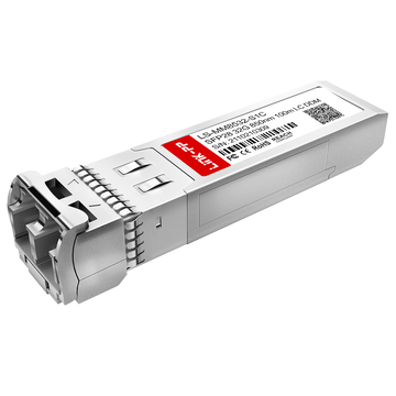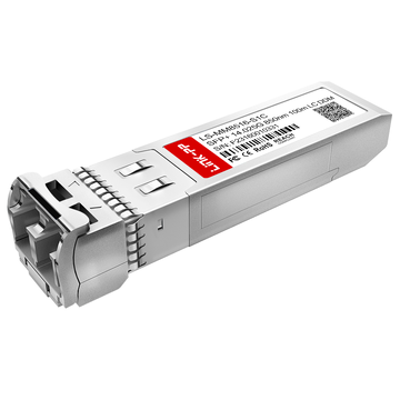
The Cisco DS-SFP-FC16G-SW is a shortwave 16Gbps Fibre Channel SFP+ module commonly used in modern storage area networks (SANs) to deliver high-speed, low-latency data transmission over multimode fiber. For network engineers and data center planners, simply knowing the nominal specifications is not enough—understanding how hardware design and optical budget interact is critical to ensuring stable and predictable link performance.
In real-world deployments, factors such as transmit power, receiver sensitivity, fiber type, connector loss, and environmental conditions all contribute to whether a link operates reliably or experiences intermittent failures. Misjudging even a small optical margin can lead to signal degradation, increased bit error rates, or complete link loss, especially in high-density Fibre Channel environments.
This guide focuses on two essential aspects of the Cisco DS-SFP-FC16G-SW: its hardware architecture and its optical budget characteristics. By breaking down how the module works internally and how to accurately calculate and manage link budgets, this article provides a practical foundation for designing, validating, and optimizing 16G Fibre Channel connections in enterprise and data center scenarios.
✅ Overview of Cisco DS-SFP-FC16G-SW
The Cisco DS-SFP-FC16G-SW is a short-range 16Gbps Fibre Channel transceiver optimized for high-speed SAN environments, delivering reliable performance over multimode fiber within typical data center distances. It combines standardized SFP+ form factor design with 16GFC protocol compliance, making it suitable for modern storage networking scenarios that demand both speed and stability.
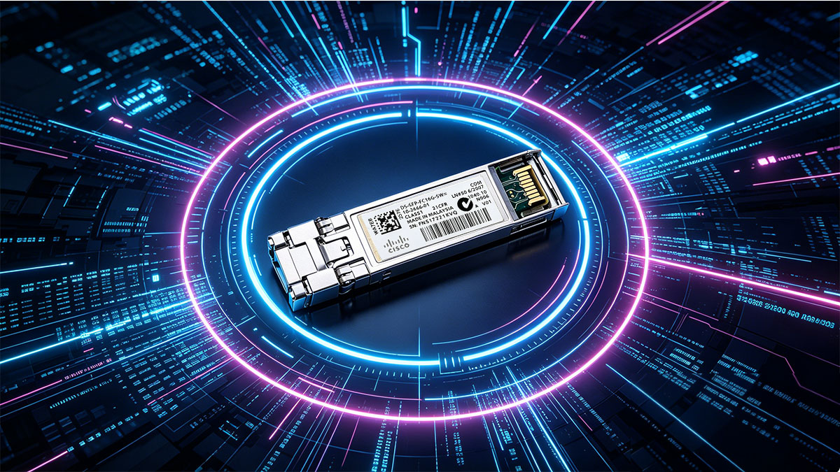
Key Specifications and Features
This module is designed to meet the performance requirements of 16G Fibre Channel while maintaining compatibility with existing infrastructure and operational efficiency in dense deployments.
| Parameter | Value | Notes |
|---|---|---|
| Data Rate | 14.025Gbps (16GFC) | Fibre Channel line speed |
| Wavelength | 850nm | Shortwave VCSEL |
| Fiber Type | Multimode (OM3/OM4) | Optimized for short distances |
| Connector | Duplex LC | Standard interface |
| Form Factor | SFP+ | Hot-swappable |
These specifications highlight that the module is purpose-built for short-distance, high-bandwidth communication, where low latency and signal integrity are essential. Its use of 850nm VCSEL technology ensures efficient transmission within multimode fiber environments, while the SFP+ form factor supports flexibility in deployment and maintenance.
Typical Application Scenarios
The Cisco DS-SFP-FC16G-SW is primarily deployed in environments where consistent, high-throughput data exchange is required over relatively short distances.
- Storage Area Networks (SANs): Used to connect Fibre Channel switches, storage arrays, and host bus adapters, ensuring fast and reliable data access.
- Data center interconnects: Ideal for rack-to-rack or within-rack connections where distances remain within multimode fiber limits.
- Enterprise storage infrastructure: Supports mission-critical applications that rely on low latency and high I/O performance.
These scenarios share a common requirement: predictable link performance within controlled distances. As a result, the module's design emphasizes stability, compatibility, and ease of integration rather than extended reach, making it a practical choice for high-density Fibre Channel deployments.
✅ Hardware Architecture and Design
The Cisco DS-SFP-FC16G-SW is built around a compact and efficient optical-electrical architecture that ensures stable 16GFC transmission within short-range environments. Its design balances signal integrity, thermal performance, and power efficiency, which are all critical in dense SAN deployments.
Core Optical Components
At its core, the module relies on proven shortwave optical technology to deliver consistent high-speed communication over multimode fiber.
- VCSEL (Vertical-Cavity Surface-Emitting Laser): Generates the 850nm optical signal with low power consumption and high modulation efficiency.
- PIN photodiode: Converts incoming optical signals back into electrical signals with high sensitivity and fast response time.
- Optical sub-assembly (OSA): Integrates laser and photodiode components to maintain alignment and signal quality.
- Digital Optical Monitoring (DOM): Provides real-time visibility into parameters such as transmit power, receive power, temperature, and voltage.
These components work together to ensure that both transmission and reception remain stable under varying operating conditions. The inclusion of DOM is particularly valuable for troubleshooting and long-term performance monitoring.
Electrical Interface Characteristics
The electrical side of the module is designed to support high-speed data transfer while maintaining signal integrity between the transceiver and the host device.
| Parameter | Description | Typical Behavior |
|---|---|---|
| Interface Standard | SFP+ (FC-PI compliant) | Supports 16GFC signaling |
| Data Encoding | Fibre Channel encoding | Optimized for low latency |
| Power Consumption | Low-power design | Typically <1W |
| Signal Integrity | High-speed differential signals | Stable at 16Gbps |
This electrical architecture ensures seamless communication with Fibre Channel switches and host bus adapters. Low power consumption is especially important in high-density switch environments, where multiple optical transceiver modules operate simultaneously.
Thermal and Mechanical Considerations
Thermal stability and physical durability are essential for maintaining consistent performance, especially in data centers with high port density.
- Operating temperature range: Typically 0°C to 70°C, suitable for controlled indoor environments.
- Metal enclosure: Provides electromagnetic interference (EMI) shielding and enhances structural integrity.
- Heat dissipation: Passive cooling design relies on proper airflow within switches.
- Mechanical reliability: Designed for repeated insertion and removal without degrading connector performance.
Proper thermal management directly impacts optical output stability. Inadequate airflow or excessive heat can affect laser performance, leading to reduced transmit power or increased error rates. Therefore, ensuring sufficient ventilation and adhering to recommended operating conditions is critical for long-term reliability.
✅ Optical Budget Fundamentals
The optical budget defines the maximum allowable signal loss between transmitter and receiver while maintaining a stable link. For the Cisco DS-SFP-FC16G-SW, understanding this value is essential to ensure that Fibre Channel connections operate reliably within specified distances and conditions.
Definition of Optical Budget
In practical terms, the optical budget represents the difference between how much optical power is launched into the fiber and the minimum power required at the receiver to correctly interpret the signal.
- Optical budget = Transmit power (Tx) – Receiver sensitivity (Rx)
- It determines the total loss a link can tolerate before performance degrades
- It directly impacts maximum transmission distance and link reliability
This concept is fundamental in Fibre Channel network design. If the total link loss exceeds the available optical budget, the connection may suffer from errors or fail entirely.
Typical Optical Parameters for DS-SFP-FC16G-SW
The module operates within a defined optical power range, which sets the boundaries for link planning and validation.
| Parameter | Typical Range | Description |
|---|---|---|
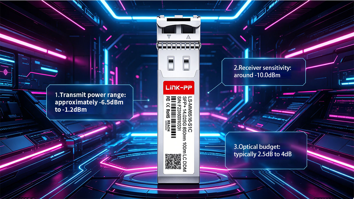
| Transmit Power (Tx) | -6.5dBm to -1.2dBm | Optical output from transmitter |
| Receiver Sensitivity | ≤ -10.0dBm | Minimum detectable signal |
| Optical Budget | ~2.5dB to 4dB | Available loss margin |
These values indicate that the DS-SFP-FC16G-SW is designed for short-range communication with limited loss tolerance. Compared to long-range transceivers, its budget is relatively small, making accurate loss estimation more important.
Factors Affecting Optical Budget
In real deployments, multiple elements contribute to total link loss, and each must be considered when evaluating whether the optical budget is sufficient.
- Fiber attenuation: Signal loss per kilometer, influenced by fiber type (OM3 vs OM4)
- Connector loss: Each LC connector pair typically introduces measurable insertion loss
- Patch panels and splices: Additional connection points increase cumulative loss
- Cable quality and bending: Poor installation or tight bends can degrade signal strength
- Environmental conditions: Temperature and aging can slightly affect optical performance
These factors combine to determine the actual link margin. Even if individual losses seem small, their cumulative effect can exceed the available optical budget. Therefore, careful planning and conservative margin allocation are necessary to maintain stable Fibre Channel links.
✅ Fiber Compatibility and Distance Performance
The Cisco DS-SFP-FC16G-SW is optimized for multimode fiber and short-distance transmission, with performance highly dependent on fiber grade and modal bandwidth. Selecting the correct fiber type directly determines achievable distance and overall link stability.
Supported Fiber Types
This optical transceiver is specifically designed for laser-optimized multimode fibers, which provide the bandwidth necessary for 16G Fibre Channel signaling.
| Fiber Type | Core Size | Optimization Level | Typical Use Case |
|---|---|---|---|
| OM3 | 50/125µm | Laser-optimized | Standard data centers |
| OM4 | 50/125µm | Enhanced bandwidth | High-performance SANs |
Both OM3 and OM4 fibers are engineered to support VCSEL-based transmission at 850nm. While they share the same core size, OM4 offers higher modal bandwidth, which translates into improved signal quality and extended reach under identical conditions.
Maximum Transmission Distances
The achievable link distance depends on fiber type and overall link quality, but typical values provide a reliable baseline for planning.
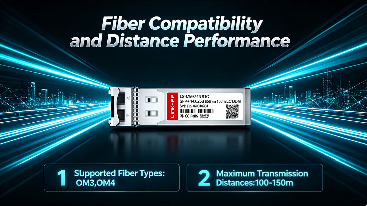
- Up to 100m over OM3 multimode fiber
- Up to 125m over OM4 multimode fiber
These distances assume standard insertion loss and properly installed cabling. In practice, actual reach may be slightly shorter depending on connector quality, patching complexity, and environmental factors. Staying within these limits helps maintain sufficient optical margin.
Bandwidth and Modal Dispersion Considerations
Signal integrity at 16Gbps is strongly influenced by modal dispersion, which becomes more significant as data rates increase.
- Modal dispersion causes pulse spreading, reducing signal clarity over distance
- OM4 fiber mitigates dispersion better than OM3, supporting cleaner signal transmission
- Higher modal bandwidth allows more reliable operation at maximum distances
- Legacy fibers such as OM1 or OM2 lack sufficient bandwidth for stable 16GFC links
Choosing the appropriate fiber is not just about distance, but also about maintaining low error rates and consistent performance. For environments where link reliability is critical, OM4 is generally preferred due to its improved tolerance to dispersion and better overall signal integrity.
✅ Optical Link Budget Calculation in Practice
Accurate optical link budget calculation determines whether a Fibre Channel link will operate reliably under worst-case conditions. For the Cisco DS-SFP-FC16G-SW, the relatively limited optical budget means even small miscalculations can lead to instability, making precise and conservative planning essential.
Step-by-Step Calculation Method
A correct calculation must be based on worst-case parameters and include all potential sources of loss, not just nominal values.
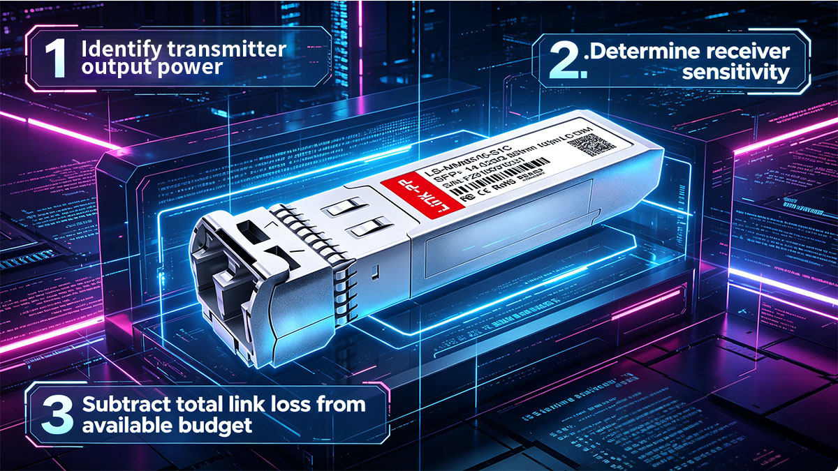
- Step 1: Use minimum transmit power (Tx min), not typical values
- Example: -6.5dBm instead of average output
- Reason: Ensures the weakest possible signal is still viable
- Step 2: Use maximum receiver sensitivity threshold (Rx max)
- Example: -10.0dBm
- This represents the minimum signal level required for error-free operation
- Step 3: Calculate available optical budget
- Optical budget = Tx(min) – Rx(max)
- In this case: ~3.5dB
- Step 4: Identify all link loss contributors
- Fiber attenuation (distance-dependent)
- Connector insertion loss
- Patch panels or cross-connects
- Potential hidden losses (dust, misalignment, bending)
- Step 5: Compare total loss against available budget
- Ensure total loss < optical budget
- Reserve margin for long-term reliability
This structured approach avoids overly optimistic assumptions and ensures the link remains stable even under degraded conditions.
Example Scenario (Engineering-Level Breakdown)
A more realistic calculation should include both deterministic loss and uncertainty factors.
| Loss Element | Typical Value | Engineering Consideration |
|---|---|---|
| Fiber (OM4, 100m) | ~0.35dB | Based on ~3.5dB/km attenuation |
| LC Connectors (2x) | ~1.0dB total | 0.5dB per mated pair (worst-case) |
| Patch Panel | ~0.3–0.5dB | Depends on quality and density |
| Contingency Loss | ~0.5dB | Dust, aging, micro-bending |
In this scenario:
- Estimated total loss ≈ 2.15dB to 2.35dB
- Available budget ≈ 3.5dB
- Remaining margin ≈ 1.1dB to 1.3dB
This margin is acceptable but not generous. It indicates that the link is viable, yet sensitive to additional degradation. Adding more patch points or using lower-quality connectors could easily consume the remaining margin.
Safety Margin Recommendations
A stable Fibre Channel link should always include reserved margin beyond calculated losses to handle variability and aging.
- Minimum recommended margin: 1dB (absolute lower bound)
- Preferred engineering margin: 1.5–2dB for production environments
To maintain this margin over time, consider the following:
- Limit the number of connector pairs
- Each additional pair can consume 0.3–0.5dB
- Avoid unnecessary patch panels in short links
- Use high-quality, low-loss connectors and cables
- Implement regular inspection and cleaning procedures
If the calculated margin falls below 1dB, the link may still function initially but becomes highly vulnerable to failure due to minor environmental or physical changes.
✅ Common Deployment Challenges
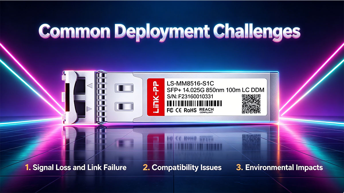
The Cisco DS-SFP-FC16G-SW operates within a tight optical margin, so most deployment issues stem from accumulated loss, compatibility constraints, or environmental instability. These challenges are rarely caused by a single factor but rather by multiple small issues combining to exceed the available optical budget.
Signal Loss and Link Instability
Most link failures are caused by excessive or poorly controlled optical loss, often underestimated during initial deployment.
A typical Fibre Channel link accumulates loss from multiple sources, and each one must be evaluated individually.
- Connector-related loss
- Dirty LC interfaces can introduce 0.3–1.0dB additional loss
- Worn or low-quality connectors increase insertion variability
- Misalignment during patching leads to intermittent signal drops
- Fiber-related loss
- Using OM3 instead of OM4 reduces effective margin at 16Gbps
- Micro-bending from tight cable routing introduces hidden attenuation
- Aging fiber can slightly increase attenuation over time
- Infrastructure-induced loss
- Each patch panel adds measurable insertion loss
- Cross-connect architectures multiply connection points
- Poor cable management increases physical stress on fibers
These factors often go unnoticed individually, but together they can exceed the 2.5–4dB optical budget, leading to CRC errors, frame loss, or link flapping.
Compatibility and Interoperability Issues
Even when optical power levels are within range, compatibility issues can prevent links from establishing or operating correctly.
A key challenge in Fibre Channel environments is the strict interoperability requirements between transceiver modules and switches.
- Vendor-specific coding
- Some switches only accept transceivers with specific EEPROM identifiers
- Non-matching modules may be rejected or operate in a degraded mode
- Firmware dependencies
- Switch firmware may enforce compatibility checks
- Upgrades can change transceiver validation behavior
- Mixed environment risks
- Combining equipment from different vendors can introduce inconsistencies
- Differences in DOM reporting or calibration may complicate diagnostics
These issues are not related to physical signal quality but can still result in link failure, making validation and compatibility testing critical before deployment.
Environmental and Thermal Constraints
Environmental conditions directly affect optical performance, particularly in high-density data center environments.
Thermal and contamination factors can gradually degrade link quality even if initial deployment is correct.
- Temperature effects
- Elevated temperatures reduce laser output power
- Receiver sensitivity can shift under thermal stress
- High port density switches may create localized hotspots
- Airflow limitations
- Inadequate cooling reduces transceiver lifespan
- Blocked airflow leads to uneven thermal distribution
- Contamination risks
- Dust on fiber endfaces increases insertion loss
- Repeated plugging without cleaning accumulates debris
- Contamination is a leading cause of unexplained link degradation
These environmental factors are often overlooked because they do not immediately cause failure, but they reduce margin over time and increase the likelihood of intermittent issues.
✅ Optimization Strategies for Reliable Performance
Ensuring stable operation of the Cisco DS-SFP-FC16G-SW requires more than meeting basic optical budget requirements. Long-term reliability depends on reducing avoidable losses, improving physical deployment quality, and continuously monitoring link health.

Best Practices for Physical Deployment
A well-structured physical layer design directly reduces optical loss accumulation and improves long-term stability.
These practices focus on minimizing insertion loss and preventing avoidable degradation.
- Reduce connection points in the signal path
- Prefer direct links over multi-stage patching
- Each additional LC pair adds measurable loss (~0.3–0.5dB)
- Use laser-optimized multimode fiber
- OM4 is preferred for higher modal bandwidth and better margin
- Avoid mixing OM3 and OM4 within the same link path
- Maintain proper bend radius
- Excessive bending introduces micro-loss and signal distortion
- Cable routing should avoid tight corners and cable stress points
- Ensure connector cleanliness
- Dirty endfaces are a primary cause of unexpected attenuation
- Cleaning before every insertion reduces insertion loss variability
These measures are especially important in high-density SAN environments where small inefficiencies accumulate quickly across multiple links.
Monitoring and Diagnostic Strategy
Even a well-designed optical link can degrade over time, so continuous monitoring is essential for maintaining performance stability.
- Utilize Digital Optical Monitoring (DOM) effectively
- Track Tx/Rx power trends rather than single snapshots
- Identify gradual degradation before failure occurs
- Establish baseline measurements
- Record initial optical power levels after deployment
- Use baseline comparisons to detect drift over time
- Monitor for early warning indicators
- Rising error rates (CRC errors, frame loss)
- Declining receive power trends
- Increased retransmission events
- Correlate optical and network metrics
- Combine switch logs with DOM readings
- Identify whether issues are physical-layer or protocol-layer related
This proactive approach allows issues to be resolved before they escalate into full link failures.
Network Design Considerations for Stability
System-level design choices significantly influence how well optical links perform under real operating conditions.
- Keep SAN topology simple where possible
- Fewer hops reduce cumulative loss and complexity
- Direct switch-to-storage connections improve predictability
- Avoid marginal design limits
- Do not design links at maximum theoretical distance
- Leave margin for future infrastructure changes
- Segment high-density areas
- Prevent excessive heat buildup around transceivers
- Improve airflow distribution across switch ports
- Plan for scalability
- Ensure optical budget supports future expansion or re-cabling
- Avoid designs that require near-limit operation from the start
A stable Fibre Channel environment is achieved not just by correct installation, but by intentionally designing below maximum limits to maintain long-term operational headroom.
✅ Future Trends in Fibre Channel Optics
Fibre Channel modules are evolving toward higher speeds, lower power consumption, and improved integration density. For transceivers like the Cisco DS-SFP-FC16G-SW, these trends define how current 16G deployments fit into next-generation storage networking architectures.
Transition Toward Higher-Speed Generations
The industry is steadily moving beyond 16G Fibre Channel toward higher throughput standards, driven by increasing storage demands and virtualization workloads.
- 32GFC and 64GFC adoption
- Designed to double or quadruple data throughput compared to 16GFC (such as DS-SFP-FC32G-SW)
- Requires tighter signal integrity and improved optical components
- Impact on legacy 16G infrastructure
- 16G modules remain widely used in existing SANs due to cost efficiency
- Mixed-speed environments require careful interoperability planning
- Upgrade cycles are typically phased rather than immediate replacement
- Architecture shift considerations
- Higher speeds reduce acceptable link margins
- Shorter maximum distances become more common at higher data rates
These changes indicate that 16G optics like DS-SFP-FC16G-SW will continue to serve as a stable baseline technology in established data centers, even as newer standards emerge.
Advances in Optical Efficiency and Component Design
Improved optical component technology is enabling more efficient and stable transceiver performance across all Fibre Channel generations.
- Enhanced VCSEL performance
- Better modulation efficiency reduces power consumption
- Improved thermal stability supports denser deployments
- Receiver sensitivity improvements
- More advanced photodiode designs increase signal detection accuracy
- Lower noise levels improve overall link margin reliability
- Power efficiency optimization
- Modern transceivers are designed to reduce per-port power usage
- Critical for high-density switch environments with hundreds of ports
These advancements do not necessarily increase distance dramatically in short-range optics like 16G SW optics, but they significantly improve stability and energy efficiency at scale.
Increasing Importance of Interoperability and Multi-Vendor Ecosystems
As Fibre Channel environments become more complex, interoperability has become a key focus area in optical module design and deployment.
- Multi-vendor compatibility requirements
- Enterprises often deploy mixed hardware environments
- Transceivers must reliably interoperate across different switch platforms
- Standardization improvements
- Stronger adherence to Fibre Channel specifications improves predictability
- Reduced dependency on vendor-specific optical tuning
- Firmware and validation alignment
- Greater emphasis on firmware-level compatibility checks
- Increased use of DOM-based diagnostics for cross-platform monitoring
This trend reduces operational friction and allows more flexible infrastructure design, especially in large-scale SAN deployments.
✅ Conclusion
The Cisco DS-SFP-FC16G-SW plays a critical role in 16G Fibre Channel storage networks, where stable optical performance and accurate budget planning directly determine link reliability. Understanding its hardware design and optical budget behavior is essential for building predictable, low-latency SAN connections in enterprise environments.
Core Takeaways
The key insights from this guide can be summarized into several practical engineering principles that define successful deployment and long-term stability.
- The Cisco DS-SFP-FC16G-SW is optimized for short-range 16GFC transmission over multimode fiber, making OM3/OM4 selection critical for performance stability
- Optical budget management is the primary factor governing link reliability, with even small losses significantly impacting margin in high-speed environments
- Real-world deployment success depends on controlling cumulative losses from fiber attenuation, connectors, and patch infrastructure rather than relying on nominal specifications
- Proper monitoring through DOM and proactive margin planning helps prevent degradation-related failures over time
- Environmental stability and physical installation quality are as important as optical specifications in maintaining long-term link integrity
These points highlight that 16G Fibre Channel optics are not just about hardware capability, but about disciplined system-level design and ongoing operational control.
Final Perspective and Practical Direction
In modern data center architectures, reliable Fibre Channel performance is achieved through a combination of correct transceiver selection, precise optical budgeting, and consistent infrastructure optimization. The Cisco DS-SFP-FC16G-SW remains a stable and widely adopted solution in environments where predictable short-reach connectivity is required, but its performance is highly dependent on how well the surrounding optical ecosystem is engineered.
For organizations looking to improve SAN reliability, reduce optical margin risks, or standardize fiber infrastructure practices, focusing on disciplined link design is the most effective approach to long-term stability.
For more technical resources, deployment guidance, and compatible optical solutions for enterprise networking environments, you can explore LINK-PP Official Store, where a wide range of optical modules and connectivity solutions are available to support scalable and reliable network architectures.