As data centers transition toward higher densities, the QSFP 100G DR (100GBASE-DR) has emerged as a pivotal solution for modernizing optical interconnects. Unlike traditional 100G architectures that rely on multiple laser lanes, the QSFP 100G DR utilizes Single-Lambda technology powered by PAM4 modulation. This shift significantly reduces hardware complexity and power consumption, providing a more efficient, cost-effective path for high-bandwidth data transmission over distances up to 500m.
Beyond its immediate performance benefits, the QSFP 100G DR serves as a critical bridge for seamless 400G migration. By aligning the per-lane signaling of 100G ports with 400G DR4 interfaces, operators can leverage breakout configurations to scale their infrastructure without a total hardware overhaul. This blog explores the technical core of Single-Lambda 100G solutions and why they are becoming the standard for leaf-to-spine connectivity and hyperscale data center deployments.
💫 What Is QSFP 100G DR and Why It Matters for Single-Lambda Networks
The QSFP 100G DR represents a transformative shift in optical networking, moving away from complex multi-lane configurations toward a streamlined single-wavelength approach. By consolidating 100G of data into a single optical stream, this technology provides the foundation for high-efficiency, low-latency connectivity within modern high-density environments.
Definition of QSFP 100G DR (100GBASE-DR Standard)
The QSFP 100G DR is an optical transceiver module designed for 100-Gigabit Ethernet over single-mode fiber, strictly adhering to the IEEE 802.3cd 100GBASE-DR standard. The "DR" stands for "Data center Reach," signifying its optimization for short-to-medium distances typical of intra-data center cabling.
Unlike legacy modules, the 100G DR converts four lanes of 25G electrical signals into a single 100G optical lane (Single-Lambda). This integration is achieved through advanced signaling, allowing it to interface seamlessly with modern switch ASICs that natively support 100G electrical SerDes.
Evolution from Multi-Lambda to Single-Lambda Architectures
Historically, achieving 100G required "Multi-Lambda" solutions like 100G LR4 or CWDM4, which multiplex four separate 25G optical wavelengths onto a single fiber. While effective, this required four sets of lasers and receivers, increasing the physical footprint, heat output, and potential points of failure within the module.
The evolution to Single-Lambda architectures replaces this complexity by using a single laser operating at a higher baud rate. This transition is a direct response to the industry's need for higher port density and reduced power-per-bit, mirroring the shift in the 400G and 800G markets toward unified 100G-per-lane signaling.
Key Technical Characteristics and Reach Capabilities
The core characteristic of the QSFP 100G DR is its use of PAM4 (4-level Pulse Amplitude Modulation) signaling at a central wavelength of 1310nm. This allows it to transmit twice the data per clock cycle compared to traditional NRZ signaling, enabling the 100Gbps throughput on a single optical carrier.
In terms of reach, the 100G DR is specified for distances up to 500m over OS2 single-mode fiber. While shorter than the 2km or 10km limits of CWDM4 or LR4, this 500m reach covers the vast majority of leaf-to-spine connections in modern "Hyperscale" and "Cloud" data center layouts.
Role in Modern Data Center Interconnects
In the current networking landscape, the QSFP 100G DR serves as the essential building block for high-radix switch fabrics. Its primary role is to provide a low-cost, high-density interconnect for the "lower" layers of the data center, specifically connecting server-access switches to the aggregation or spine layer.
Perhaps most importantly, the 100G DR is the "glue" that enables 400G interoperability. Because a 400G DR4 transceiver is essentially four 100G DR lanes bundled together, the QSFP 100G DR allows network operators to break out 400G ports into four discrete 100G paths, facilitating a phased and flexible upgrade to next-generation speeds.
💫 QSFP 100G DR Technology Overview and Core Components
The efficiency of the QSFP 100G DR stems from its sophisticated integration of high-speed electronics and simplified optics. By leveraging cutting-edge signal processing and advanced modulation, this technology compresses massive data throughput into a single optical stream, reducing the physical component count while maximizing performance.
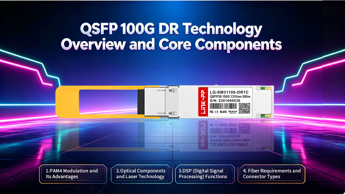
PAM4 Modulation and Its Advantages
At the heart of the QSFP 100G DR is PAM4 (4-Level Pulse Amplitude Modulation). Unlike traditional NRZ (Non-Return-to-Zero) signaling, which transmits only one bit per symbol using two voltage levels, PAM4 utilizes four distinct signal levels to transmit two bits per symbol. This effectively doubles the data rate without requiring a doubling of the optical bandwidth.
The primary advantage of PAM4 is its ability to enable 100Gbps transmission over a single wavelength (lambda). This reduces the "baud rate" requirements on optical components, allowing the industry to use more mature and cost-effective lasers while still achieving the high-speed throughput demanded by next-generation data centers.
Optical Components and Laser Technology
The QSFP 100G DR typically employs a highly integrated TOSA (Transmitter Optical Sub-Assembly) featuring a single EML (Electro-absorption Modulated Laser) or a Silicon Photonics-based integrated circuit. Because it only requires one laser rather than the four found in legacy CWDM4 or LR4 modules, the optical design is significantly more streamlined, leading to higher reliability and better manufacturing yields.
On the receiving end, a single ROSA (Receiver Optical Sub-Assembly) captures the 1310nm signal. This simplified "1-laser, 1-detector" architecture is the key to the module’s compact form factor and its ability to maintain high signal integrity over 500-meter spans of single-mode fiber.
DSP (Digital Signal Processing) Functions
The DSP (Digital Signal Processing) chip is the "brain" of the QSFP 100G DR module. Its primary role is to manage the complex transition between the electrical and optical domains. It performs critical tasks such as adaptive equalization to compensate for signal distortions and Forward Error Correction (FEC) termination, which ensures data accuracy despite the inherently lower signal-to-noise ratio of PAM4.
Furthermore, the DSP handles the retiming of the four 25G electrical lanes (or two 50G lanes) coming from the switch and aggregates them into the single 100G optical output. Without the advanced computational power of modern DSPs, achieving stable 100G transmission on a single wavelength would be impossible due to dispersion and noise constraints.
Fiber Requirements and Connector Types
The QSFP 100G DR is designed to operate over OS2 Single-Mode Fiber, utilizing the standard 1310nm window where fiber attenuation is low. Because it is a "point-to-point" single-wavelength solution, it typically uses standard Duplex LC connectors, making it physically compatible with existing fiber patch panels and infrastructure used for older 10G or 40G Long Reach standards.
For breakout applications — such as connecting a 400G DR4 port to four 100G DR modules — operators utilize MPO-to-LC fanout cables. This flexibility allows the 100G DR to fit into a variety of cabling architectures, supporting both direct point-to-point links and complex structured cabling systems in high-density environments.
💫 QSFP 100G DR Advantages in Single-Lambda 100G Deployments
Adopting QSFP 100G DR technology offers a strategic advantage by optimizing the physical and economic footprint of high-speed networks. By leveraging a single-wavelength design, organizations can achieve superior operational efficiency and performance consistency compared to legacy multi-lane solutions.
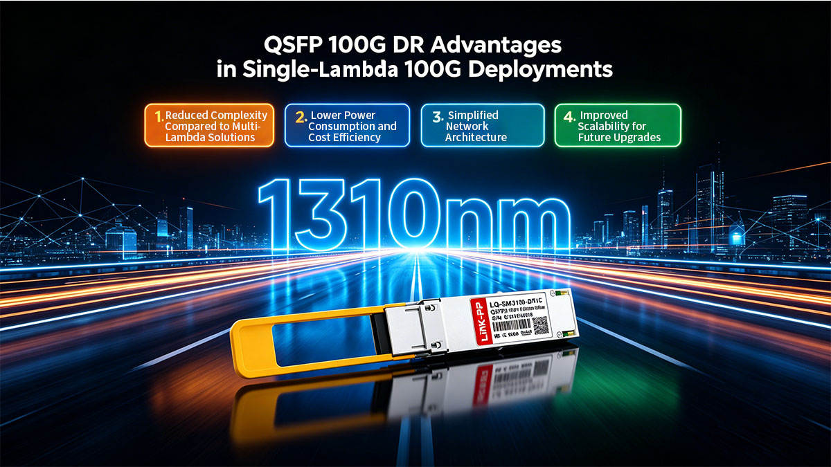
Reduced Complexity Compared to Multi-Lambda Solutions
The most immediate benefit of the QSFP 100G DR is the radical simplification of its internal optical design. Traditional 100G modules like LR4 or CWDM4 require four separate lasers, four optical drivers, and a complex multiplexer/demultiplexer to combine different wavelengths onto a single fiber. In contrast, the 100G DR utilizes a single-lambda approach, eliminating the need for optical mux/demux components and significantly reducing the number of potential failure points within the transceiver.
Lower Power Consumption and Cost Efficiency
By reducing the component count from four optical lanes to one, the QSFP 100G DR inherently consumes less power, which is a critical factor for cooling high-density racks. This streamlined architecture also leads to lower manufacturing costs over time, as it requires fewer high-value optical components. For data center operators, this translates to a dual economic benefit: a lower initial capital expenditure (CAPEX) per port and reduced ongoing operational expenses (OPEX) related to energy consumption.
Simplified Network Architecture
The transition to single-lambda 100G simplifies the overall network hierarchy by aligning the optical lane speed with the electrical lane speed of modern switch ASICs. This alignment removes the necessity for "gearbox" chips that were previously required to translate between different lane rates, thereby reducing latency and improving signal integrity. This architectural harmony allows for a more "plug-and-play" experience when deploying high-radix switches in enterprise and cloud environments.
Improved Scalability for Future Upgrades
The QSFP 100G DR is designed with the future in mind, providing a clear evolutionary path toward 400G and 800G networking. Because it shares the same 100G-per-lane signaling used in higher-speed standards (like 400G DR4), it enables seamless breakout capabilities and ensures that current fiber infrastructure remains compatible with next-generation hardware. This forward-compatibility protects long-term investments, allowing for incremental capacity upgrades without the need for a complete architectural overhaul.
💫 Comparing QSFP 100G DR vs. 100G LR4 and 100G PSM4 Solutions
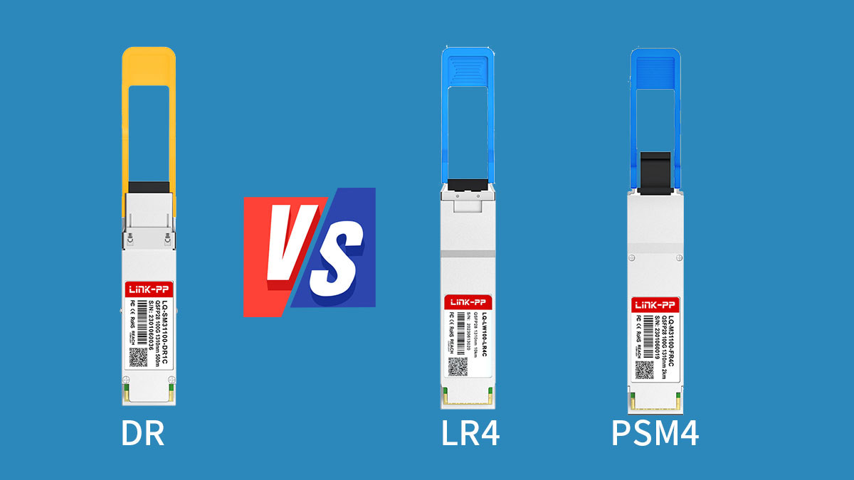
Choosing the right 100G transceiver requires a careful balance between transmission distance, fiber infrastructure costs, and architectural future-proofing. While legacy standards like LR4 and PSM4 served the industry well during the NRZ era, the QSFP 100G DR introduces a streamlined single-wavelength approach designed specifically for the efficiencies of modern data centers.
The following table provides a quick reference to the primary technical differences between these three common 100G solutions:
| Feature |
QSFP 100G DR |
QSFP 100G LR4 |
QSFP 100G PSM4 |
| Transmission Type |
Single-lambda (1×100G) |
4-lambda WDM (4×25G) |
Parallel optics (4×25G) |
| Modulation |
PAM4 |
NRZ |
NRZ |
| Max Reach |
Up to 500m |
Up to 10km |
Up to 2km (typically 500m) |
| Fiber Type |
Duplex SMF (LC) |
Duplex SMF (LC) |
8-fiber SMF (MPO) |
| Wavelength |
1310nm |
around 1295nm, 1300nm, 1304nm, and 1309nm |
1310nm |
Single-Lambda vs. Four-Lane WDM Architecture
The fundamental difference lies in how the 100Gbps data stream is physically transmitted. Legacy 100G LR4 uses Wavelength Division Multiplexing (WDM) to combine four 25Gbps optical signals onto a single pair of fibers, requiring four lasers and a complex optical multiplexer. Similarly, PSM4 uses four separate parallel fibers (via MPO connectors) to transmit four 25Gbps signals.
In contrast, the QSFP 100G DR simplifies this to a single optical lane. By moving the complexity from the optical domain to the digital domain (via the DSP), it eliminates the need for multiple lasers and wavelength-combining optics. This reduction in physical components significantly increases the Mean Time Between Failures (MTBF) and simplifies the internal assembly of the transceiver.
Cost-Efficiency Analysis: Transceiver Price vs. Reach
When evaluating cost-efficiency, the 100G LR4 is typically the most expensive due to its high-precision lasers designed for 10km long-reach applications. While PSM4 transceivers are often cheaper than LR4, they impose a "hidden cost" in the form of expensive MPO-12 cabling and higher-density patch panels. The 100G DR strikes a middle ground by offering a lower transceiver price point than LR4 while utilizing standard, low-cost Duplex LC fiber.
For intra-data center distances (under 500m), the 100G DR offers the best Total Cost of Ownership (TCO). It avoids the cabling premium of PSM4 and the over-engineered laser costs of LR4, making it the most economical choice for high-volume leaf-to-spine deployments where extreme long-distance capability is unnecessary.
Power Budget Comparisons for High-Density Racks
Power consumption is a critical constraint in high-density switch environments. Traditional 100G LR4 modules often consume significantly more power because they must drive four separate laser diodes simultaneously. Even PSM4 modules, while simpler than LR4, still require powering multiple optical paths.
The QSFP 100G DR is optimized for lower power envelopes, as it only operates a single laser and a single receiver. Although the DSP inside the 100G DR consumes power for PAM4 processing, the overall thermal footprint is generally lower or more efficient per gigabit than legacy four-lane solutions. This reduced heat dissipation allows network engineers to populate switches more densely without exceeding the thermal cooling capacity of the rack.
💫 Critical Use Cases for QSFP 100G DR in Enterprise Networking
The versatility of the QSFP 100G DR makes it a cornerstone for modern enterprise and cloud-scale infrastructures. By providing a reliable 500-meter reach over single-mode fiber, it addresses the specific bandwidth and distance requirements of today’s high-density physical layouts while ensuring a smooth transition to next-generation speeds.
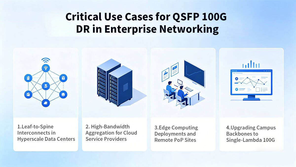
Leaf-to-Spine Interconnects in Hyperscale Data Centers
In the classic Clos architecture of hyperscale data centers, the link between leaf and spine switches requires consistent, low-latency performance. The QSFP 100G DR is the primary choice for these interconnects because it offers a significant reduction in complexity and cost for the vast majority of cable runs.
- Optimized Reach: Since most leaf-to-spine distances in a single data hall fall well under 500m, the 100G DR provides the exact performance needed without the unnecessary cost overhead of long-range optics.
- High-Density Reliability: By utilizing a single laser, these modules generate less heat, allowing for fully populated switch faceplates which is essential for maintaining the massive throughput required by hyperscale fabrics.
High-Bandwidth Aggregation for Cloud Service Providers
Cloud Service Providers (CSPs) face the constant challenge of aggregating massive amounts of data from various customer tenants into a unified core. The QSFP 100G DR facilitates this aggregation by providing a standardized, high-speed interface that is both power-efficient and easy to manage.
This technology allows CSPs to scale their aggregation layers horizontally. Because the single-lambda 100G signal is natively compatible with newer 400G and 800G switch chipsets, providers can aggregate multiple 100G client links into higher-speed uplinks more efficiently than with legacy multi-lane modules, reducing the "tax" on rack space and power.
Edge Computing Deployments and Remote PoP Sites
Edge computing environments and remote Points of Presence (PoPs) often operate under strict space and environmental constraints. The QSFP 100G DR is particularly well-suited for these "micro-data centers" where reliability and simplicity are paramount.
- Environmental Stability: The simplified internal architecture of the 100G DR is less sensitive to the slight temperature fluctuations often found in edge locations compared to complex WDM-based optics.
- Standardized Cabling: By using standard duplex single-mode fiber, edge operators can maintain a lean inventory of patch cables and accessories, simplifying remote maintenance and reducing the risk of installation errors in unmanned sites.
Upgrading Campus Backbones to Single-Lambda 100G
Enterprises upgrading campus networks to 100G can leverage QSFP 100G DR to transition from legacy multi-lane optics to a more streamlined single-lambda approach. This simplifies both physical infrastructure and long-term network management.
- Seamless migration from 10G/40G: Supports gradual upgrades without major redesign.
- Reduced fiber footprint: Uses duplex SMF instead of multi-fiber bundles.
- Future-ready design: Aligns with 400G upgrade paths and breakout strategies.
By adopting QSFP 100G DR, organizations can modernize campus backbones while minimizing disruption and preparing for future bandwidth growth.
💫 Seamless Migration to 400G Networks Using QSFP 100G DR
The transition from 100G to 400G is no longer a disjointed leap, thanks to the architectural alignment provided by single-lambda technology. By standardizing on 100Gbps per optical lane, the QSFP 100G DR acts as a fundamental building block that allows legacy 100G infrastructure to communicate directly with next-generation 400G hardware.
Breaking Down 400G DR4 into 4x 100G DR Paths
One of the most significant advantages of the QSFP 100G DR is its native interoperability with the 400G DR4 standard. Because a 400G DR4 transceiver is essentially composed of four independent 100G DR transmitters and receivers in a single module, a high-speed 400G port can be "broken out" into four discrete 100G links. This eliminates the need for expensive and power-hungry conversion hardware, allowing a 400G spine switch to connect directly to four individual 100G leaf switches using standard single-lambda signaling.
Utilizing MPO-to-LC Fanout Cables for Connectivity
To physically implement the breakout from 400G to 100G, network engineers utilize MPO-to-LC fanout cables. The 400G DR4 end uses an MPO connector to transmit the four parallel channels, which are then separated into four pairs of Duplex LC connectors that plug into standard QSFP 100G DR transceivers. This cabling strategy not only simplifies the physical deployment but also allows data centers to scale their bandwidth incrementally by upgrading individual endpoints without replacing the entire structured cabling system.
Managing Heterogeneous Port Speeds in a Single Chassis
Modern high-radix switches often operate in heterogeneous environments where some racks remain at 100G while others are upgraded to 400G or even 800G. The QSFP 100G DR provides the flexibility to manage these mixed speeds within a single chassis by maintaining a consistent modulation format (PAM4) across all ports. This consistency ensures that the network operating system (NOS) can easily manage port channelization, allowing administrators to allocate bandwidth dynamically based on the specific needs of each server rack or tenant.
Optimizing Port Density with High-Radix Switches
As switch ASICs move toward higher radix counts, the ability to utilize 100G-per-lane signaling becomes crucial for maximizing faceplate density. By using 400G DR4 ports in breakout mode to connect with QSFP 100G DR modules, data center operators can achieve much higher 100G port densities than would be possible with traditional dedicated 100G ports. This optimization reduces the total number of switches required in the fabric, leading to significant savings in rack space, power consumption, and overall cooling requirements.
💫 Installation and Best Practices for QSFP 100G DR Solutions
Ensuring the long-term reliability of a QSFP 100G DR deployment requires more than just plugging in the modules; it demands a disciplined approach to physical handling and system monitoring. Because single-lambda PAM4 signaling is more sensitive to signal degradation than legacy NRZ formats, adhering to industry best practices during installation is vital for maintaining link stability.
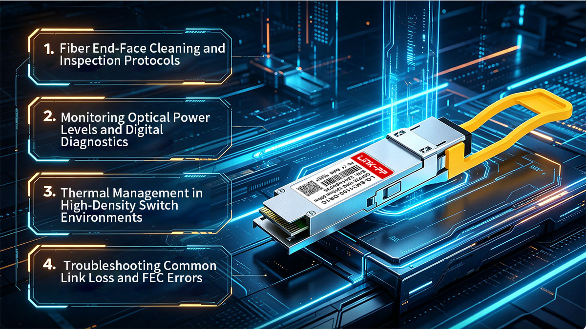
Fiber End-Face Cleaning and Inspection Protocols
The transition to high-speed 100G single-lambda optics makes fiber cleanliness more critical than ever. Since the 100G DR relies on precise optical power levels to maintain signal integrity, even microscopic dust particles on the connector end-face can cause significant back-reflection or insertion loss, leading to intermittent bit errors.
- The "Inspect Before You Connect" Rule: Technicians should always use a fiber inspection microscope to verify that both the transceiver port and the fiber jumper are free of contaminants. If debris is detected, specialized lint-free cleaners or "one-click" cleaning tools should be used to restore the surface.
- Preventing Permanent Damage: Connecting dirty fibers doesn't just block the signal; the high-intensity light from a 100G laser can actually "burn" contaminants into the glass or the transceiver lens. Consistent cleaning protocols prevent this permanent damage and ensure the longevity of your expensive hardware investments.
Monitoring Optical Power Levels and Digital Diagnostics
Once the hardware is installed, proactive management through Digital Optical Monitoring (DOM) is essential for identifying potential issues before they cause a network outage. The QSFP 100G DR module provides real-time data that allows administrators to track the "health" of the optical link through the switch’s Command Line Interface (CLI) or SNMP management tools.
- Tx/Rx Power Thresholds: Administrators should regularly monitor the transmit (Tx) and receive (Rx) optical power levels. A significant drop in Rx power often points to a dirty connector, a failing patch cable, or an over-bent fiber optic line.
- Real-Time Internal Metrics: Beyond light levels, DOM provides insight into the module's internal temperature and supply voltage. Establishing a baseline for these metrics allows for the implementation of automated alerts, ensuring that any deviation from normal operating parameters is addressed immediately.
Thermal Management in High-Density Switch Environments
High-radix switches fully populated with QSFP 100G DR modules generate substantial heat, which can impact the performance of the internal DSP chips if not managed correctly. While the single-lambda design is more efficient than multi-lane alternatives, the concentration of electronics in a small form factor necessitates strict attention to airflow.
- Optimized Airflow Paths: Ensure that the switch’s cooling direction (Front-to-Back or Back-to-Front) matches the data center’s hot-aisle/cold-aisle containment strategy. Obstructions such as messy cable management should be cleared to prevent "hot spots" at the faceplate.
- Operating Temperature Safeguards: Modern 100G DR modules include internal thermal sensors that will trigger a shutdown if temperatures exceed safe limits. To avoid this, rack-level cooling should be calculated based on the maximum power draw of the specific transceivers used, rather than just the switch base power.
Troubleshooting Common Link Loss and FEC Errors
Because 100G DR technology utilizes Forward Error Correction (FEC) to achieve reliable data transmission, troubleshooting requires a shift in perspective compared to legacy 10G or 40G links. A link that is "up" may still be experiencing a high Pre-FEC bit error rate, which can lead to performance degradation.
- Analyzing FEC Statistics: If a link experiences intermittent instability, the first step is to check the FEC statistics on the switch port. A high number of "Correctable Errors" is normal for PAM4, but an increase in "Uncorrectable Errors" typically indicates a physical layer issue, such as poor fiber quality or excessive optical loss.
- Physical Layer Validation: When a link fails to come up entirely, verify that the wavelengths match (1310nm) and that the reach does not exceed the 500m limit. Since the 100G DR is often used in breakout scenarios, double-check that the port mapping on the 400G end matches the physical LC connections on the 100G end to ensure proper channel alignment.
💫 Conclusion: Selecting the Right QSFP 100G DR Solution for Your Infrastructure
The shift to QSFP 100G DR technology marks a turning point in networking, replacing complex multi-lane architectures with efficient, single-lambda paths. By aligning 100G signaling with next-generation 400G and 800G standards, the 100G DR solution effectively reduces power consumption and hardware complexity while providing a seamless breakout path for future-proof scalability. For data centers and enterprise backbones limited to 500-meter reaches, it stands as the most cost-effective and reliable choice for high-density deployments.
As you optimize your infrastructure for higher bandwidth and lower latency, choosing high-quality, interoperable hardware is paramount. LINK-PP provides industry-leading optical modules designed to meet the rigorous demands of modern cloud and enterprise environments. To find the ideal transceiver for your specific networking needs, explore the high-performance solutions available at the LINK-PP Official Store.


